SIGNIFY Keene Stonco User manual

MOUNTING INSTRUCTIONS:
1. Attach the cast junction box to surface with screws (hardware by
others)
2. Run conduit to junction box if application calls for it and pull
supply leads into junction box with at least 6” lead showing.
Location Environments.
3. Place gasket (from polybag) and make wiring connections from
driver in Heatsink to supply leads (See wiring diagram)
4. Remove Globe, with the gasket in place, attach Heatsink to
junction box by using the two (2) screws provided in polybag.
Insert the screws through the holes on the inside of Heatsink. Next
align the screws with the holes on the “Adaptor Plate” mounted
on the “Junction Box” and tighten. Do not touch LED and do not
damage or soil the reflector during installation.
(Care must be given to not cross thread)
6. Replace Guard onto Globe. (Care must be given not to cross
thread. Do not over tighten set screw when securing guard)
VAPOR PROOF LIGHT
SUITABLE FOR WATTAGES: 14W
4.52’’ x 4.52’’ x 11.04’’
MOUNTING INSTRUCTIONS
FIXTURE IS SUITABLE FOR WET LOCATION
DO NOT INSTALL CELINING MOUNT VERSION OF THIS FIXTURE ON WALL
INSTALL W/ GLOBE FACING DOWN ONLY
NOT FOR WASH DOWN APPLICATION NOT FOR USE IN RANGE HOODS
CAUTION:
weatherproof silicone sealant (not included) around the edge of the Wall Box and/or Junction Box. This is especially important with an uneven
wall surface. Silicone all plugs and unused conduit entries.
IMPORTANT: READ BEFORE REMOVING FIXTURE FROM CARTON. RETAIN FOR FUTURE REFERENCE.
ordinances. These codes and ordinances supersede any and all instruction contained herein. Installation should be performed only by a
licensed and bonded electrician and a person familiar with the construction and operation of the product and the hazards involved in the
installation and operation of this product. Proper grounding is required for safety. Make certain power is OFF before installing or maintaining
for the the product not installed under those guidelines and those contained in this document. See wiring diagram on back.
109.8mm
[4.32"]
Gasket EVA
Junction Box
Gasket
Gasket
Phillips pan head Brass screws
#10 - 24 UNC x 0.75”
2pcs
Heatsink
Globe Gasket
Phillips flat head screws
#10 - 24 UNC x 1.875”
2pcs
Globe
Guard
109.0mm[4.29"]
114.8mm[4.52"]
141.2mm
[5.56"]
280.5mm[11.04"] 243.0mm[9.57"]
This fixture must be wired and installed in accordance with the National Electrial Code and all state and applicable local codes and
fixture. Failure to do so may increase the risk of personal injury, property damage, fire, and death. The manufacturer takes no responsibility
For proper weatherproof function,gaskets must be seated properly and all screws inserted and tightened firmly. Apply
Note: Be sure to use Teflon tape to seal 1/2” NPT threads for Wet
5. Replace Globe onto fixture by threading until tight

MOUNTING INSTRUCTIONS
SUITABLE FOR WATTAGES: 14W
1.
2.
3.
FIGURE 1
TROUBLESHOOTING:
1.
2.
3.
LIGHTING
FIXTURE
(+) LINE
(-) COMMON
GROUND
BLACK
WHITE
GROUND
VAPOR PROOF LIGHT
ON-OFF WIRING METHOD:
Universal voltage driver permits operation at 120V through 277V, 50
or 60HZ. Units ordered with (480V) suffix are 480V, 60HZ.
For Non-Dimming, follow the wiring directions as in FIG. 1
Connect the GROUND wire from fixture to supply ground.
Connect the white fixture lead to the (-)COMMON supply lead
Connect the black fixture lead to the (-)LINE supply lead
Check that the line voltage at fixture is correct
Is there voltage at the lamp fixture wires?If there is no voltage,check
all connections
Ensure that the fixture is grounded properly

INSTRUCTIONS DE MONTAGE :
1. Fixer la boîte de jonction moulée à la surface à l’aide de vis (quincaillerie par
d’autres).
2. Si l’application le requiert, acheminer un conduit jusqu’à la boîte de jonction et tirer
les fils d’alimentation dans la boîte de jonction en laissant dépasser au moins 6 po de
fils. Note : dans les emplacements mouillés, être sûr d’utiliser un ruban en Téflon pour
sceller les filets ½ po NPT.
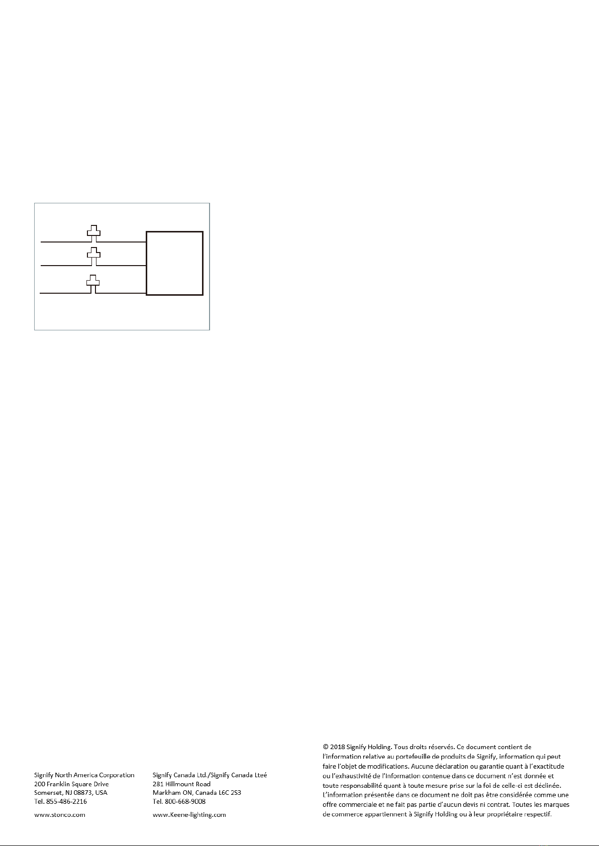
3. Poser la garniture d’étanchéité (dans le sac en polyéthylène) et réaliser les
connexions du pilote dans le dissipateur thermique aux fils d’alimentation (se reporter
au schéma de câblage).
4. Retirer le globe, la garniture d’étanchéité en place, puis fixer le dissipateur
thermique à la boîte de jonction au moyen des deux (2) vis fournies dans le sac en
polyéthylène. Insérer les vis à travers les trous à l’intérieur du dissipateur thermique.
Ensuite, aligner les vis sur les trous de la « plaque adaptateur » montée sur la boîte
de jonction et serrer.
6. Replacer le protecteur autour du globe (éviter de fausser ou détériorer le filetage.
Ne pas trop serrer la vis de blocage en fixant le protecteur).
CONVIENT À UNE PUISSANCE DE: 14W
4,52 po x 4,52 po x 11,04 po
INSTRUCTIONS DE MONTAGE
LUMINAIRE ÉTANCHE À LA VAPEUR
MISE EN GARDE : Pour une étanchéité adéquate aux intempéries, toutes les garnitures d’étanchéité doivent être bien en place et toutes les vis
insérées et serrées solidement. Appliquer un joint à la silicone étanche aux intempéries (NON inclus) au pourtour de la boîte murale et/ou de la
boîte de jonction. Ceci est surtout important dans le cas d’une surface inégale. Protéger à la silicone toute obturation ou entrée de conduit non
utilisée.
IMPORTANT : À LIRE AVANT DE RETIRER LE LUMINAIRE DE LA BOÎTE. CONSERVER POUR RÉFÉRENCE ULTÉRIEURE.
Ce luminaire doit être câblé et installé conformément au National Electrical Code (NEC) et tous les codes et réglementations gouvernementaux
et locaux applicables. Ces codes et réglementations ont préséance sur les présentes instructions. L’installation doit exclusivement être réalisée
par un électricien cautionné muni d’une licence et une personne au courant de la construction et du fonctionnement du produit et des risques
liés à l’installation et au fonctionnement de ce produit. Une mise à la terre adéquate est requise pour la sécurité. S’assurer de la mise HORS
TENSION avant de procéder à l’installation ou l’entretien. Omettre de le faire peut augmenter le RISQUE DE BLESSURE CORPORELLE,
DOMMAGE MATÉRIEL, INCENDIE ET PERTE DE VIE. Le fabricant décline toute responsabilité pour un produit dont l’installation ne respecte
pas ces directives et celles contenues dans ce document. Se reporter au schéma de câblage au verso.
Ne pas toucher aux DEL ni endommager ou salir le réflecteur durant l’installation.
5. Replacer le globe sur le luminaire en le vissant jusqu’à ce qu’il soit bien fixé
(attention à ne pas croiser ou détériorer le filetage.)
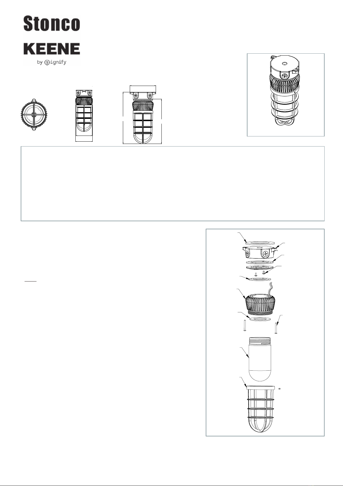
Boîte de jonction
Garniture d’étanchéité
Vis à tête cylindrique Phillips
No 10 – 24 UNC x 0,78 po
2 pièces
Garniture d’étanchéité
Dissipateur thermique
Garniture d’étanchéité
du globe
Globe
Protecteur
Vis à tête fraisée Phillips
No 10 – 24 UNC x 1,875 po
2 pièces
109.8mm
[4.32po]
109.0mm[4.29po]
114.8mm[4.52po]
141.2mm
[5.56po]
280.5mm[11.04po]
243.0mm[9.57po]
CE LUMINAIRE CONVIENT AUX EMPLACEMENTS MOUILLÉS
NE PAS INSTALLER LA VERSION POUR MONTAGE AU PLAFOND SUR UN MUR.
INSTALLER EXCLUSIVEMENT AVEC LE GLOBE FACE VERS LE BAS.
NON CONÇU POUR LES APPLICATIONS DE LAVAGE À GRANDE EAU,
NI POUR USAGE DANS LES HOTTES DE CUISINE OU LES
EMPLACEMENTS DANGEREUX.

INSTRUCTIONS DE MONTAGE
LUMINAIRE ÉTANCHE À LA VAPEUR
CONVIENT À UNE PUISSANCE DE: 14W
MÉTHODE DE CÂBLAGE AVEC FONCTION INTERRUPTEUR (ON-OFF) SEULEMENT :
Le pilote à tension universelle permet un fonctionnement de 120 V à
277 V, 50 ou 60 Hz. Les unités commandées avec le suffixe (480V)
sont pour une tension de 480 V, 60 Hz. Pour un luminaire sans fonction
de gradation d’intensité, suivre les directions du câblage de la FIG. 1.
1. Connecter le fil de mise à la terre (MALT) du luminaire à la MALT de
l’alimentation.
2. Connecter le fil blanc du luminaire au fil d’alimentation NEUTRE (-).
3. Connecter le fil noir du luminaire au fil d’alimentation PHASE (+).
FIGURE 1
DÉPANNAGE :
1. Vérifier que la tension d’alimentation au luminaire est adéquate.
2. Y a-t-il une tension secteur aux fils de lampe du luminaire ? Sinon,
vérifier toutes les connexions.
3. S’assurer que le luminaire est adéquatement mis à la terre.
LUMINAIRE
(+) PHASE
(-) NEUTRE
MALT
NOIR
BLANC
MALT
Table of contents
Languages:
Other SIGNIFY Landscape Lighting manuals
Popular Landscape Lighting manuals by other brands

SLV
SLV 231370 instruction manual

Kichler Lighting
Kichler Lighting HOLMDEN Assembly instructions

Volt
Volt VUL-6703 BBZ Series installation instructions

Prilux
Prilux Pincho Jardin I Quick installation guide

Malibu Boats
Malibu Boats LT2 Assembling & installation instructions

ZANEEN
ZANEEN Frisbee L10B0069 installation guide

FOSCARINI
FOSCARINI Havana terra Assembly instructions

Enchanted Garden
Enchanted Garden 343-1858 instructions

Endon
Endon YG-865-SS instruction manual

Powerbeauty
Powerbeauty PBB-250 instruction manual

Malibu Boats
Malibu Boats CL635P user guide

AMP Lighting
AMP Lighting AFL-40 B-BZ Series Installation & maintenance guide