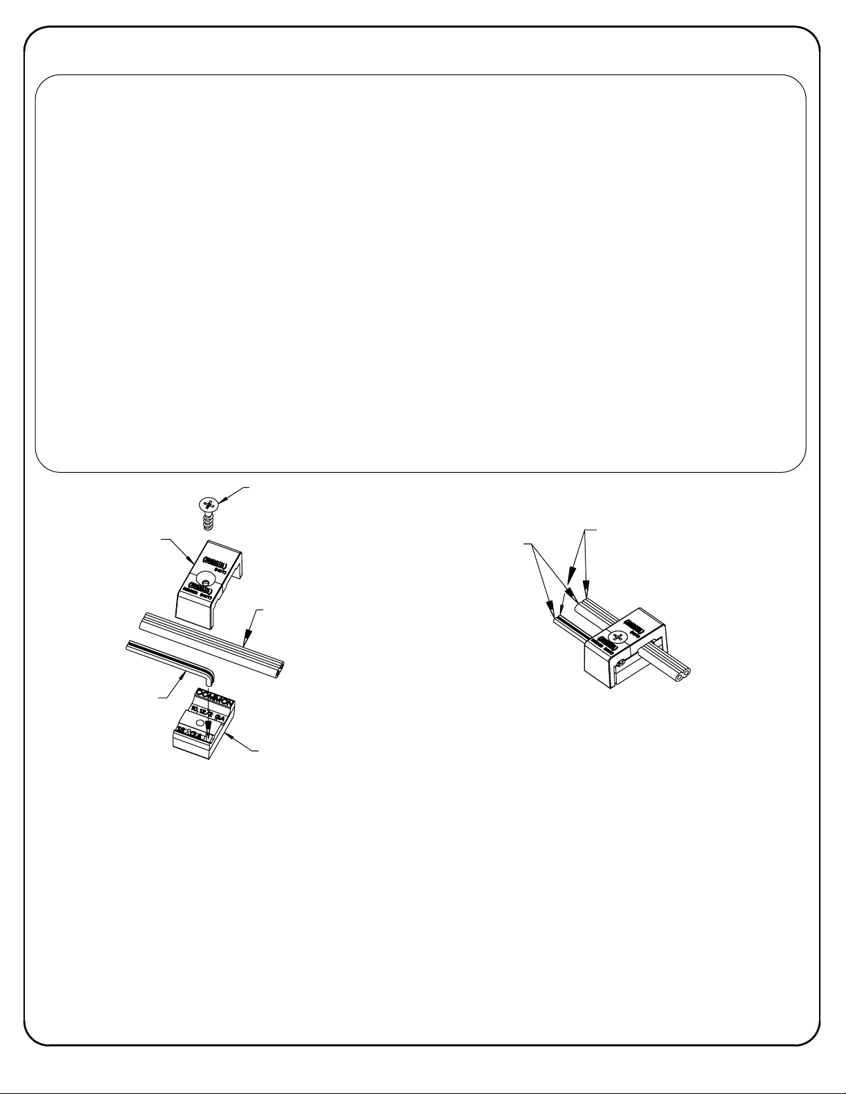
SIGNIFY HADCO iUL516 User manual

INSTRUCTIONS PERTAINING TO A RISK OF FIRE OR INJURY TO PERSONS-IMPORTANT SAFETY INSTRUCTIONS
Lighted lamp is HOT! WARNING- To reduce the risk of FIRE OR INJURY TO PERSONS: Turn off/unplug and
allow to cool before replacing lamp. Lamp gets HOT quickly! Contact only switch/plug when turning on.
Do not touch hot lens, guard, or enclosure (see diagram/picture). Keep lamp away from materials that
may burn. Do not touch the lamp at any time. Use a soft cloth. Oil from skin may damage lamp. Do not
operate the luminaire fitting with a missing or damaged shield. SAVE THESE INSTRUCTIONS.
Xenon lamps do not require additional shielding.
OPTIONNELS A INSTALLER AU
MOYEN DE VIS AUTOTARAUDEUSES]
[DISPOSITIFS D'ANCRAGE
[DOUILLE A DEUX BROCHES]
[JOINT EN SILICONE]
[COUVERT "TWIST-LOCK"]
RACCORD DE CONDUIT ETANCHE]
[ENROBE EN USINE
[BOITIER DU LUMINAIRE]
[CABLE A BASSE TENSION]
[MATERIAU GRANULEUX]
[FORMER UN MONTICULE
AUTOUR LUMINAIRE,
NIVEAU DU SOL]
A BASSE TENSION]
[CONNECTEUR DE CABLE
[VIS DE FIXATION DU COUVERCLE]
CONNECTOR
LOW VOLTAGE
PROVISION, TAKES
OPTIONAL ANCHORING
GRANULAR MATERIAL
MOUND UP GROUND
SCREW (BY OTHERS)
FACTORY SEALED
MR16 LAMP (BY OTHERS)
[MR16 LAMPE (NON
COMPRIS)]
FIXTURE HOUSING
#10-24 THREAD FORMING
TWIST-LOCK FIXTURE COVER
COVER LOCKING SCREW
LOW VOLTAGE CABLE
SILICONE GASKET
LIQUID-TIGHT CONDUIT FITTING
BI-PIN TYPE SOCKET
32000777, revision L
INSTALLATION INSTRUCTIONS:
12V MICRO INGROUND
page 1 of 3
This fixture is intended for installation in accordance with the National Electrical Code and local code
specifications. Failure to adhere to these codes and instructions may result in serious injury and/or damage
to the ballast and void the warranty. These instructions do not purport to cover all details or variations in
equipment, nor to provide for every possible contingency related to installation, operation, maintenance,
or mounting situation. Should specific problems occur that are not addressed by these instructions, contact
your Sales Representative or distributor for assistance. Retain these instructions for future reference.
IF THIS IS THE ONLY PAGE
MOVE THE DRAWING
NUMBER AND REVISION
NOTE TO THE RIGHT 0.60"
AND ADD THE PHILIPS SHIELD
HERE (IT CAN BE COPIED
FROM PAGE 2 OF THE
DEFAULT TEMPLATE)
The warning notes to the left are
required by ANSI/UL 1838-2009 &
CSA 22.2 No. 250.7-07 for Tungsten
Halogen/Xenon Luminaires only.
However, these warnings should
be left on all low voltage
instruction sheets due to the fact
that the information is beneficial
to have on
all low voltage fixtures
regardless of lamp type.
Signify North America Corporation
200 Franklin Square Drive
Somerset, NJ 08873, USA
Phone: 855-486-2216
Signify Canada Ldt./ Signify Canada Ltée
281 Hillmount Road
Markham ON, Canada L6C 2S3
Phone: 800-668-9008
www.hadco.com

CAUTION!
SERVICING INSTRUCTIONS
1. To prevent electrical shock, always turn power OFF before installing or servicing this fixture.
2. DO NOT hold fixture by, or pull, the low voltage cable. If wire is pulled, it may break the liquid tight seal and void
warranty.
3. DO NOT loosen or remove the liquid tight connector. This will damage the factory set seal and result in possible
leakage.
4. Do not exceed max wattage listed on label inside fixture.
5. Fixtures must not be installed in insulating materials such as vermiculite, bark, etc. for the full depth of the fixture,
as they may cause the fixture to overheat and void the warranty.
6. When backfilling, housing flange should be just above ground level as shown in the illustration. Fixture housing
should be surrounded by a 3" min. layer of sand or gravel to insure proper drainage. It is recommended that
fixtures not be placed in low locations where water could accumulate and stand for long periods of time. Hilling
up earth around fixture will promote good water run-off and prevent debris accumulation.
7. For concrete pour installation, fixture must be installed with a 4" min. bed of gravel below, and must use the CP5
accesory kit.
8. In areas with high water tables, the fixture may be anchored to prevent fixture buoyancy.
9. Regularly check lens and keep it cleared of debris (mulch, leaves, etc.) as this could cause a fire.
1. Excavate soil for fixture placement. Contour the hole to the shape of the fixture, allowing for 3" min. around and
under the fixture for placement of granular material.
2. Lamp Installation/Replacement
a) Loosen cover locking screw. Remove cover by turning it counterclockwise. Remove lens and o-ring.
b) Install specified lamp. Use a standard 12V MR16 bi-pin lamp.
c) To remove a lamp, pull on the lamp reflector. Do not pull on the small bulb within the reflector.
d) When installing a new lamp, do not touch the halogen bulb within the reflector. Natural oils from skin may
cause shortened lamp life.
e) The o-ring seating surfaces must be clean before attempting to replace the lens, etc. Be certain that the
o-ring is is clean and in good condition. Re-install o-ring.
f) Re-install lens and fixture cover. Look through (3) slots in top of cover, hand tighten cover by turning clockwise
until the (3) tabs on the cover touch the stops on the housing.
g) Tighten the cover locking screw in place.
3. Make certain there is no water or moisture inside the fixture prior to re-assembly.
4. The lens will require periodic cleaning. Wipe off the outside of the lens with a soft cloth. DO NOT use abrasive
cleaner. This may damage the lens.
page 2 of 3
32000777, revision L

common (smooth)
hot (ribbed)
body
fixture cable
supply cable
cover
LOW VOLTAGE CABLE CONNECTOR INSTRUCTIONS
Low voltage cable connector to be used with 10 or 12 gauge supply cable and 18 gauge fixture cable. Philips
recommends using SPT-3 water resistant (marked "WA", "W" or similar marking) supply cable such as our SCW500-
10/BSCW500-10 or our SCW100-12/BSCW100-12. Philips also recommends ordering the entire system, which includes the
power console (maximum 25 Amps, 15 Volts per circuit), fixture(s) (low voltage cable connector included) and supply
cable to ensure proper installation and operation.
When using our supply cable, it can be laid on top of the ground, placed under "ground cover" (that is, shallow burial less
than 6 inches or 15.2 cm deep), or directly buried in accordance with the NEC. If not using our cable, per UL 1838-Standard
for Low Voltage Landscape Lighting Systems, the secondary cable must be SPT-3 or suitable for wet locations, sunlight
resistant and direct burial per UL 493 and sized per UL 1838, and it must be buried less than 6 inches (15.2 cm).
Philips recommends a minimum depth of 4 inches when burying in the lawn to prevent damage from aerators or other lawn
plugging equipment.
The 18 gauge fixture cable (provided with fixture) must be protected by routing in close proximity to the fixture or secured
to a building structure such as a house or deck. The fixture cable must be cut off so that it is connected to the low voltage
cable connector within 6 inches (15.2 cm) of the fixture or the building structure. When making an underground connection
to the 10 or 12 gauge supply cable (not provided), the fixture cable must not be buried more than 6 inches (15.2 cm).
WARNING-Mount the luminaire in or on non-combustible mounting surfaces only.
WARNING-Risk of Electric Shock. Install all luminaires 10 feet (3.05m) or more from a pool, spa, or fountain.
Connect the supply cable to the terminals on the power console (transformer) and turn ON.
1.
Disassemble the connector by removing the Phillips head screw.
2.
Inspect the connector to ensure the prongs are straight. If the prongs are bent, straighten with pliers.
3.
Insert the end of the fixture cable into the square opening in the connector body. Bend wire over so that wire is laying in
4.
the recess marked '18 GA'. This will help hold the wire in place while performing steps 5 and 6. Only 2-wire cable is to be
used and the common (smooth) wire and hot (ribbed) wires must be oriented as shown.
Press the supply cable into the recess marked '10,12/2 GA' on the connector body. Again the common (smooth) wires
5.
and the hot (ribbed) wires must be oriented as shown.
Press the connector cover onto the connector body, making sure the screw holes line up with each other.
6.
Assemble the connector by tightening the Phillips head screw. NOTE: Make sure the metal prongs in the connector
7.
pierce all 4 wires; the fixture will light as the prongs pierce the wires.
screw
page 3 of 3
32000777, revision L
IF THIS IS NOT THE LAST
PAGE, DELETE THE PHILIPS
SHIELD MARK AND PLACE IT
ON THE LAST PAGE
Other SIGNIFY Landscape Lighting manuals
Popular Landscape Lighting manuals by other brands

SLV
SLV 231370 instruction manual

Kichler Lighting
Kichler Lighting HOLMDEN Assembly instructions

Volt
Volt VUL-6703 BBZ Series installation instructions

Prilux
Prilux Pincho Jardin I Quick installation guide

Malibu Boats
Malibu Boats LT2 Assembling & installation instructions

ZANEEN
ZANEEN Frisbee L10B0069 installation guide

FOSCARINI
FOSCARINI Havana terra Assembly instructions

Enchanted Garden
Enchanted Garden 343-1858 instructions

Endon
Endon YG-865-SS instruction manual

Powerbeauty
Powerbeauty PBB-250 instruction manual

Malibu Boats
Malibu Boats CL635P user guide

AMP Lighting
AMP Lighting AFL-40 B-BZ Series Installation & maintenance guide