SIGRIST PhaseGuard C User manual

Document number: 11026E
Version: 4
Valid from: Software Vx26
INSTRUCTION MANUAL
PhaseGuard C/T/HT
In-line Interface Monitor

Copyright© SIGRIST-PHOTOMETER AG, subject to changes without notice 9/2016
SIGRIST-PHOTOMETER AG
Hofurlistrasse 1
CH-6373 Ennetbürgen
Switzerland
Tel. +41 41 624 54 54
Fax +41 41 624 54 55
info@photometer.com
www.photometer.com

Instruction Manual PhaseGuard C/ T/ HT
11026E/4 i
Content
1. Notes to the user...........................................................................................................1
1.1. General information..............................................................................................1
1.2. Explanation of symbols .........................................................................................2
2. Instrument description ...................................................................................................3
2.1. General information about the PhaseGuard ..........................................................3
2.2. Technical data.......................................................................................................8
3. General safety pointers................................................................................................10
3.1. Behavior in emergency........................................................................................10
3.2. Dangers when using properly..............................................................................11
3.3. Residual risk ........................................................................................................12
3.4. Warning and danger symbols on the instrument.................................................12
4. Mechanical mounting..................................................................................................13
5. Electrical installation ....................................................................................................14
5.1. Safety pointers for the electrical installation ........................................................14
5.2. Installation of the PhaseGuard ............................................................................15
5.3. Installation of the SICON control unit, field bus...................................................16
6. Initial start-up ..............................................................................................................17
6.1. Commissioning procedure ..................................................................................17
6.2. Perform zero calibration......................................................................................19
7. Operation ....................................................................................................................20
8. Servicing......................................................................................................................21
8.1. Servicing schedule...............................................................................................21
8.2. Replacing the desiccant.......................................................................................22
8.3. Cleaning the sensor head....................................................................................23
8.4. Replacing gasket of the in-line housing and blanking plate .................................25
9. Troubleshooting ..........................................................................................................27
10. Customer service information ......................................................................................27
11. Decommissioning & storage ........................................................................................28
12. Packaging & transport .................................................................................................29
13. Disposal.......................................................................................................................30
14. Spare parts ..................................................................................................................31
15. Appendix.....................................................................................................................32
15.1. Dimension sheet PhaseGuard-MB .......................................................................32
15.2. Overview of gaskets on the PhaseGuard .............................................................33
15.3. PhaseGuard connection diagram.........................................................................34
16. Index ...........................................................................................................................35


Notes to the user Instruction Manual PhaseGuard C/ T/ HT
11026E/4 1
1. Notes to the user
1.1. General information
This Instruction Manual provides the user with the most important information up to and in-
cluding commissioning. Information such as operation, servicing, troubleshooting and more
are described in greater detail in the Reference Manual.
The Instruction Manual is intended for all persons who are responsible for mounting,
installing and commissioning the instrument.
DOC. NO.
TITLE
CONTENT
11027E
Reference Manual
More sophisticated menu functions and work-
steps for advanced users.
This document can be downloaded from
www.photometer.com (first time registration re-
quired).
11018E
Data sheet
Descriptions and technical data about the pho-
tometer.
11052E
Service Manual
Repair and conversion instructions for service
engineers.
11050DEF
Declaration of conformity
Compliance with the underlying directives and
standards.
This Instruction Manual has been written by SIGRIST PHOTOMETER AG. Copying or modify-
ing the content or giving this document to third parties is permitted only with express writ-
ten consent.
The Instruction Manual is a component of the product and should always be close at hand.
Registered uses can download the latest version (color) at www.photometer.com.
It can also be ordered from our representative in your country. Section 10
Purpose of the
Instruction Manual
Target group
Additional
documentation
Copyright regulations
Storage location of
the Instruction
Manual
Instruction Manual PhaseGuard C/ T/ HT Notes to the user
2 11026E/4
1.2. Explanation of symbols
Below is a description of all danger symbols that occur in this Instruction Manual.
Danger due to electrical shock that may result in serious bodily injury or
death.
Non-observance of this danger warning may lead to electrical shocks and death.
Danger due to explosion that may result in serious bodily injury or death.
Non-observance of this notice may cause explosions resulting in serious material damage and
death.
Warning about bodily injury or hazards to health with long-term effects.
Non-observance of this warning may lead to injuries with possible long-term effects.
Notice about possible material damage.
Non-observance of this notice may cause material damage to the instrument and its periph-
erals.
Below is an explanation of all pictograms that occur in this Instruction Manual.
Additional information about the current topic.
Practical procedures when working with the photometer and control unit.
Work on the PC.
Danger symbols
DANGER!
EXPLOSION
HAZARD!
WARNING!
CAUTION!
Pictograms

Instrument description Instruction Manual PhaseGuard C/ T/ HT
11026E/4 3
2. Instrument description
2.1. General information about the PhaseGuard
2.1.1. View of a measuring station
Figure 1: Overview of PhaseGuard C/ T/ HT
Photometer PhaseGuard
USB interface for configuring the
instrument
Connection cable between the
instrument and the customer-side
control system
Customer-side control system
Varivent® in-line housing or
compatible (optional)
Sample line
2.1.2. Proper use
The PhaseGuard and its peripherals are designed to detect phase transitions in liquids.
Possible areas of application:
Food and beverage industry
Milk processing industry
Chemical and pharmaceutical industry
2.1.3. User requirements
The instrument may be operated only by trained technical personnel.
The instrument may be operated only by persons who are familiar with the content of
the Instruction Manual and Reference Manual.

Instruction Manual PhaseGuard C/ T/ HT Instrument description
4 11026E/4
2.1.4. Conformity
Current technological principles were followed in designing and manufacturing the photom-
eter. They comply with the usual guidelines concerning duty to take due care and safety.
The system meets the requirements applicable within the European Union (EU) for electro-
magnetic compatibility (EMC) and low voltage directives (LVD) and has the CE mark.
Please refer to the separate declaration of conformity for details (document 11050DEF).
2.1.5. Use restrictions
Explosion hazard during operation in an inappropriate environment.
Use in explosion hazardous areas may cause explosions that could be lethal to persons in the
vicinity.
It is not permitted to operate the instrument in explosion hazardous areas
or rooms.
It is not permitted to use the instrument with explosive media.
Danger during operation with inappropriate media.
The use of too hot or aggressive media may cause leakage that could be lethal to persons in
the vicinity.
It is not permitted to use the measuring instrument for applications in which the medium
can attack it. Parts which contact the media: stainless steel, sapphire, gaskets.
2.1.6. Dangers when not used properly
Operation when not used properly.
Improper use can cause injuries to persons, process-related consequential damage and dam-
age to the instrument itself and its peripherals.
In the following cases the manufacturer cannot guarantee the protection of persons and the
instrument and therefore assumes no legal responsibility:
The instrument is used in a way not included in the described area of application.
The instrument is not properly mounted.
The instrument is not installed and operated in accordance with the Instruction Man-
ual.
If the instrument has been operated with accessories which SIGRIST-PHOTOMETER AG
has not expressly recommended.
Improper changes to the instrument have been performed.
The instrument has not been operated within the specifications, in particular concern-
ing pressure and temperature.
EXPLOSION
HAZARD!
DANGER!
DANGER!

Instrument description Instruction Manual PhaseGuard C/ T/ HT
11026E/4 5
2.1.7. Identification of the PhaseGuard
The photometer displays the following rating plate:
Figure 2: PhaseGuard rating plate
Manufacturer
Country of origin
Product name
Serial number
Date of manufacture
Service voltage
Frequency range
Power
Observe the Instruction Manual.
Disposal information Section 13
Instruction Manual PhaseGuard C/ T/ HT Instrument description
6 11026E/4
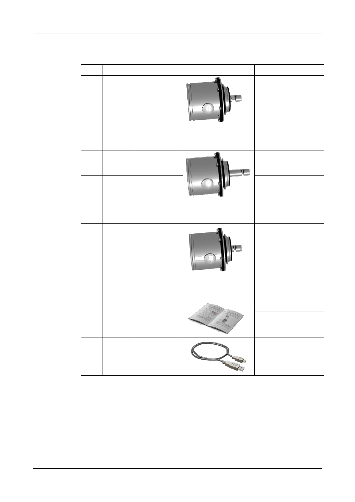
2.1.8. Scope of delivery and accessories
PCS.
ART. NO.
NAME
VIEW
VARIANT
1
118676
PhaseGuard C
Length of sensor head:
33 mm
Path length: 10 mm
Detection of phase tran-
sitions based on color
change
1
118677
PhaseGuard T
Detection of phase tran-
sitions in media with
mid-range turbidities
1
119788
PhaseGuard T
Sensor head made of
Hastelloy
1
118678
PhaseGuard HT
Length of sensor head:
56.5 mm
Path length: 5 mm
Detection of phase tran-
sitions with high turbidi-
ties
1
119123
PhaseGuard HC
For liquids with high ab-
sorption levels
1
119675
PhaseGuard HT
< DN65
Length of sensor head:
28 mm
Path length: 5 mm
Detection of phase tran-
sitions at high turbidities
for Varivent® housing <
DN65
1
20012
Instruction
Manual
11026D German
11026E English
11026F French
1
118730
USB cable
Scope of delivery
Instrument description Instruction Manual PhaseGuard C/ T/ HT
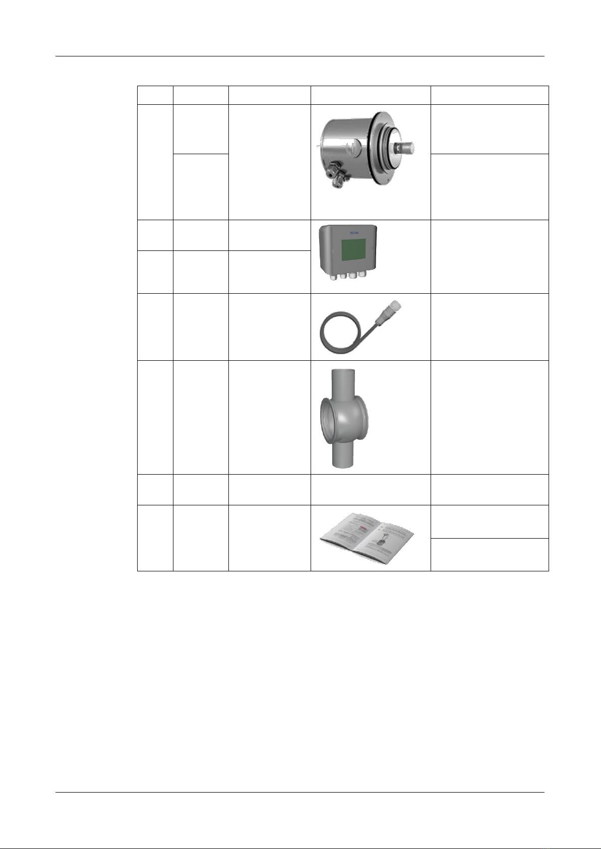
11026E/4 7
PCS.
ART. NO.
NAME
VIEW
VARIANT
1
118695
PhaseGuard
with integrated
field bus inter-
face recogniza-
ble by the larger
housing, the
two cable pene-
trations and
M12 connector
Profibus DP
118696
RTU Modbus
1
118342
SICON control
unit
1
119040
SICON M
Multichannel
control unit
1
120444
Device cable, 8-
pole, 10 m with
connector
1
Various
Varivent® in-
line housing
Various nominal widths
1
118740
Uncoated
blanking plate
1
20012
Reference Man-
ual as PDF
11027D German
11027E English
Optional accessories:
Instruction Manual PhaseGuard C/ T/ HT Instrument description
8 11026E/4
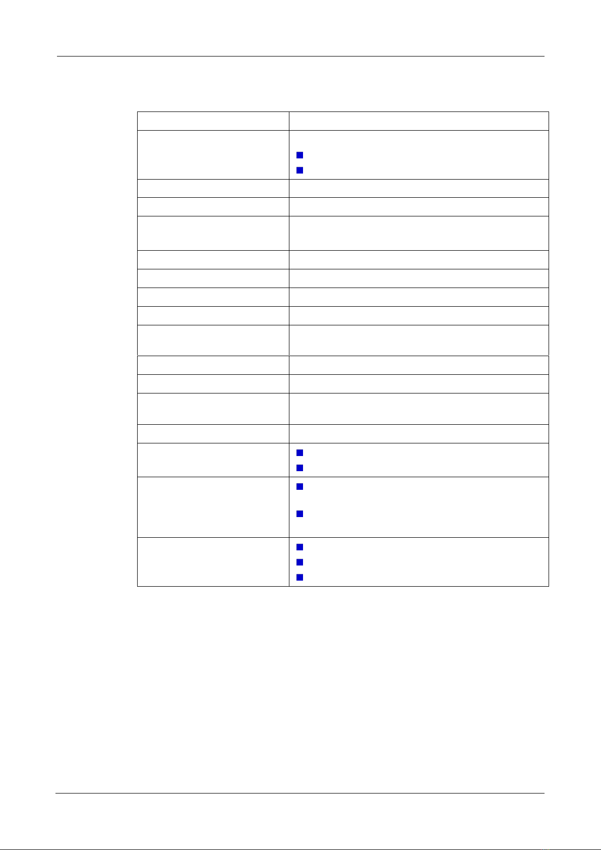
2.2. Technical data
TURBIDITY MEASUREMENT
VALUES
Measuring principle
Absorption
at 880 nm (T/HT)
at 430 nm (C/HC)
Measurement span
0 .. 100% absorption
Measuring range
0 .. 100% absorption
Sample temperature
-10 .. +100°C
120°C max. 2 hr
Ambient temperature
-10 .. +50°C
Pressure
1 MPa (10 bar) / 100°C
Resolution
0.5% absorption
Warm-up time
< 3 min
Repeatability (2 measurements
with 1 instrument)
0.5% absorption
Linearity
0.5% absorption
Temperature stability
±0.05%/K (full scale)
Reaction time
< 0.3 s at 0 seconds integration time (step response
limit switch)
Ambient humidity
0 .. 100% relative humidity
Path lengths
10 mm (T/C)
5 mm (HC/HT)
Outputs
1 x 4 .. 20 mA, galvanically separated up to max.
35 VDC relative to ground and max. 500 Ω burden
2 x switching transistor with open collector
UEXT 3 .. 30 VDC, ILmax. 8 mA
Interfaces
USB (for configuration via text file)
Modbus RTU / Profibus DP (both optional)
To optional SICON control unit

Instrument description Instruction Manual PhaseGuard C/ T/ HT
11026E/4 9
PHOTOMETER
VALUES
Service voltage
9 .. 30 VDC, 2 W (3 W with Profibus DP)
Material
Housing: stainless steel 1.4301 or 1.4307
Sensor head stainless steel 1.4404 or better
Hastelloy for PhaseGuard T (optional)
Window
Sapphire
Weight
Approx. 2.1 kg
Approx. 2.5 kg (PhaseGuard with interface card)
Dimensions
Ø 120 x 143 mm for instrument types T and C
Ø 120 x 164.5 mm with interface card
Ø 120 x 166.5 mm for instrument type HT
Ø 120 x 188 mm with interface card
Detailed dimension drawing PHASEGUARD-MB
Pipe connections
Minimum DN 40 for instrument types T and C with
Varivent® or compatible connections
Minimum DN 65 for instrument type HT with
Varivent® or compatible connections
Protection type
IP66

Instruction Manual PhaseGuard C/ T/ HT Instrument description
10 11026E/4
3. General safety pointers
3.1. Behavior in emergency
Behavior in emergency:
SIGRIST-PHOTOMETER AG instruments have no on/off switch. This is installed customer-side.
Before commissioning, clarify the following points:
Position of the on/off switch and the way it works.
Where and how the sample supply can be stopped.
Who the responsible authorities are.
MEASURE
NOTES
1.
Interrupt the service voltage to the
measuring station.
2.
Interrupt sample supply.
3.
Secure emergency location.
4.
Notify responsible institution.
CAUTION!
PROCEDURE IN
AN
EMERGENCY!
Instrument description Instruction Manual PhaseGuard C/ T/ HT
11026E/4 11
3.2. Dangers when using properly
Electrical shock due to damaged instrument or cabling.
Touching damaged cables may lead to electrical shocks with lethal consequences.
The instrument may be operated only when the cables are undamaged.
The instrument may be operated only if it has been properly installed or repaired.
Dangerous voltage inside the instrument due to galvanically separated current
output.
Touching the galvanically isolated current output may lead to electrical shocks with lethal
consequences.
The instrument must never be operated when the housing is removed.
The instrument may be opened only by trained personnel.
Bodily injury due to escaping sample liquid.
Contact with the medium may lead to burns, caustic irritations or poisoning with lethal con-
sequences.
The instrument must never be connected to leaking sample lines and operated.
The local clothing regulations must be observed during operation.
The local safety precautions must be observed during operation.
Damage due to incorrect power supply.
If the instrument is connected to an incorrect service voltage, it can be damaged.
The instrument may be connected only to voltage sources as specified on the rating plate.
Damage to the instrument caused by humidity or condensation entering the in-
strument when it is opened:
If moisture enters the instrument, it can be damaged.
Work on the inside of the instrument may be performed only in a dry room and at
room temperature. The instrument should be warm from operation or at room tem-
perature. (Condensation on optical and electrical surfaces must be avoided.)
The instrument may be opened only under these conditions (e.g. removing cover to
the usb interface).
Use of aggressive chemicals.
The use of aggressive cleaning agents can destroy surfaces on the instrument that are rele-
vant to measurement.
Do not use aggressive chemicals or cleaning agents when cleaning.
Thoroughly clean the instrument with a neutral cleaning agent if it has come into con-
tact with aggressive chemicals.
If the instrument changes hands, always include the Instruction Manual.
If the Instruction Manual is lost, you can request a replacement.
Registered users can download the current version at www.photometer.com.
DANGER!
DANGER!
DANGER!
WARNING!
CAUTION!
CAUTION!
CAUTION!
Instruction Manual PhaseGuard C/ T/ HT Instrument description
12 11026E/4
3.3. Residual risk
During operation with hot or dangerous media, the possibility of leakage cannot be
completely excluded.
Contact with the medium may lead to burns, caustic irritations or poisoning with lethal con-
sequences.
The operator is responsible for using the instrument for this purpose.
The operator must ensure that additional protection measures such as safety clothing
and similar items are available and are put to use.
To avoid faulty measurement values as much as possible, the maintenance duties
must be carried out according to the servicing schedule.
Evaluate digital output warnings and error messages to recognize them.
3.4. Warning and danger symbols on the
instrument
There are no warning or danger symbols on the PhaseGuard.
Users must ensure that they observe the safety measures as specified in the Instruction Man-
ual when working with the photometer and its peripheral equipment at all times.
Important to note:
Sections 1.2 and 3.2.
Observe local safety pointers when performing the described procedures.
DANGER!
CAUTION!

Mechanical mounting Instruction Manual PhaseGuard C/ T/ HT
11026E/4 13
4. Mechanical mounting
The instrument can be installed in horizontal or vertical sample lines using the standards-
compliant in-line housing. Figure 4
The mounting dimensional drawing (PHASEGUARD-MB) provides detailed information about
the dimensions.
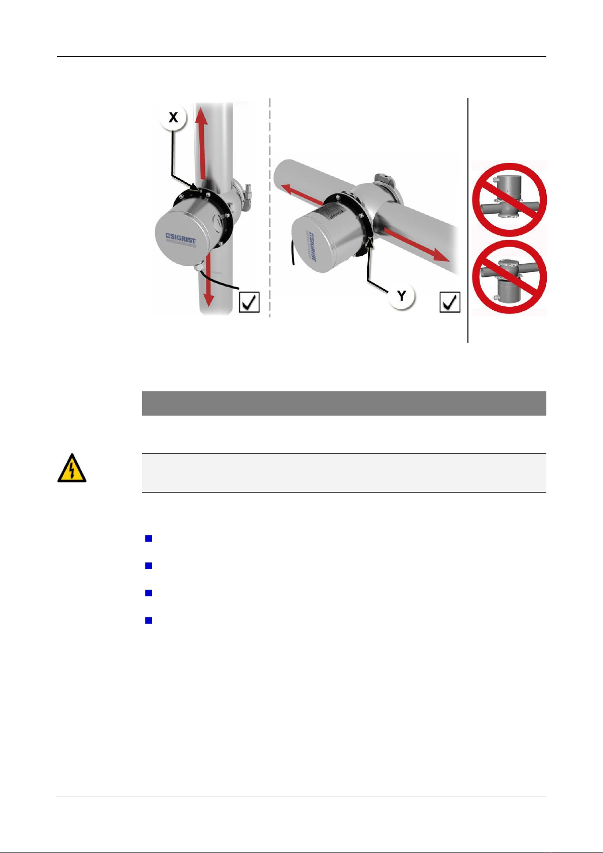
Figure 3: Position of the sensor in horizontal mounting
Photometer
Centering pin on the instrument
Sensor with measurement opening
pointing downward
Varivent® sample line
The photometer must be mounted in the line at least 0.5 m away from sight glasses
and other unwanted light sources.
In the vertical mounting position, the centering pin (2, Figure 3) must point upward
(X, Figure 4).
In the horizontal mounting position, the centering pin (2, Figure 3) must point to the
right (Y, Figure 4).
Basics of mounting
the photometer
Instruction Manual PhaseGuard C/ T/ HT Mechanical mounting
14 11026E/4
Figure 4: Correct installation in the vertical or horizontal sample lines
Figure 5: Incorrect
mounting position
5. Electrical installation
5.1. Safety pointers for the electrical installation
Dangerous voltage inside the instrument:
Connecting electrical lines can be life threatening. Parts of the system can also be damaged.
Local regulations for electrical installations must be observed at all times.
Further, the following basic principles must be observed:
The power supply 9 .. 30 VDC is to be provided by the customer. It must be stable,
low noise voltage.
Only voltages complying with the local regulations for low voltage may be used as
power supply and on the galvanically separated current output.
Because the unit has no main switch, a suitable disconnection device (switch, plug)
must be installed near the power supply.
If faults cannot be remedied, the unit must be put out of operation and protected
against inadvertent operation.
Mounting position of
the photometer
DANGER!
Mechanical mounting Instruction Manual PhaseGuard C/ T/ HT
11026E/4 15
5.2. Installation of the PhaseGuard
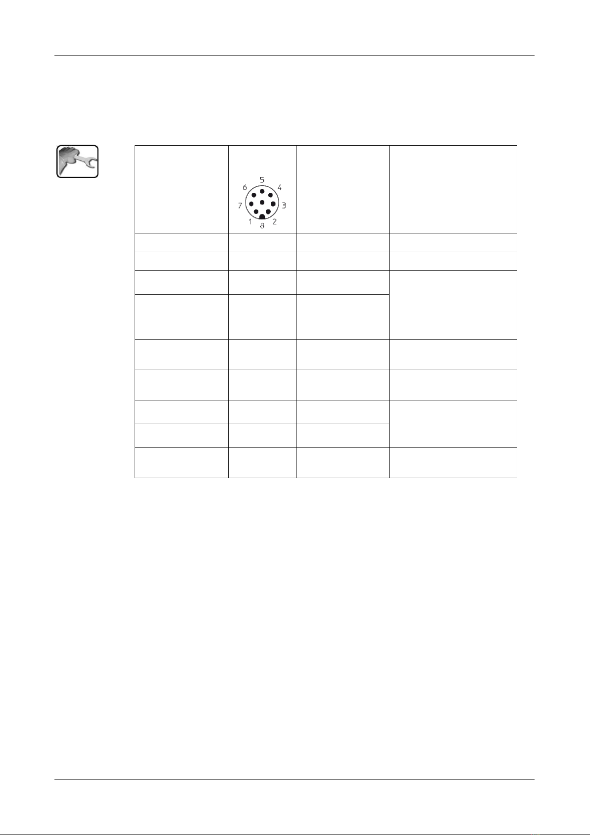
An 8-pin connector of type M12x1 with A-coding is used. A screened device cable must be
used. The connector assignment looks like the following:
Description
Connector
pin (male)
Wire color for
device cable
(art. no. 120444)
Remarks
GND supply
1
white
Supply 9 .. 30 VDC
2
brown
RS 485 A
7
blue
Serial interface for SICON
(M)
Alternative: initiate zero
calibration
Reference Manual
RS 485 B
5
gray
Digital output 1
(alarm)
6
pink
Open collector to GND
Digital output 2
(limit)
4
yellow
Open collector to GND
Current output +
8
red
Max. 35 V to ground
Max. 500 Ω burden
Factory setting: 0 .. 100%
Current output -
3
green
Shielding
Screen
Must be connected to
ground
Connecting the
photometer

Instruction Manual PhaseGuard C/ T/ HT Mechanical mounting
16 11026E/4
The standard length of the connection cable is 10 m. For greater distances, a junction box
must be inserted between the instrument and a customer-side control system or, as shown
in the figure below, with a SICON.
Figure 6: Installation of the photometer with junction box
Photometer
Junction box
Customer-side control system or
SICON.
The maximum distance (X) between SICON or a customer-side system (3) and the junction
box (2) depends on the power supply and the cross-section in use:
CROSS-SECTION
MAX. DISTANCE
FOR 12 VDC
(WITH PROFIBUS)
MAX. DISTANCE
FOR 24 VDC
(WITH PROFIBUS)
REMARKS
[mm2]
[m]
[m]
0.14
40 (20)
150 (100)
0.20
60 (30)
250 (150)
Standard version
0.34
100 (50)
400 (250)
0.50
140 (70)
600 (350)
0.75
210 (110)
800 (500)
1.00
280 (140)
800 (700)
1.50
400 (200)
800 (800)
Paired cable, complete copper-braided shielding, impedance 100-165 Ω, capaci-
tance < 60 pF/m
5.3. Installation of the SICON control unit, field bus
Installation of the optional SICON control unit as well as installation and commissioning of
the field bus interfaces are described in the Reference Manual.
Cross section for
greater distances
Cross-section
specifications
Cable structure
This manual suits for next models
2
Table of contents
Other SIGRIST Industrial Equipment manuals


