SIGRIST TurBiScat 2 Ex User manual

TurBiScat 2 Ex
sigrist.com
Bedienungsanleitung

Imprint
2 / 62
1 Imprint
Consideration of applicable standards and guidelines
The content of this document has been compiled in accordance with applicable standards and directives and
the state of the art.
The manufacturer accepts no liability for damage due to:
l
Non-compliance with the instruction manual
l
Non-intended use
l
Use of untrained staff
l
Unauthorised modifications
Copyright provisions (Copyright©)
l
This document was written by Sigrist-Photometer AG. The copyright© is held by Sigrist-Photometer AG.
l
Copying, modifying or translating the contents or passing it on to third parties is only permitted with the agree-
ment of Sigrist-Photometer AG.
l
The form (output medium) of this documentation is subject to the company
Sigrist-Photometer AG.
Manufacturer
Sigrist-Photometer AG
Hofurlistrasse 1
CH-6373 Ennetbürgen. Switzerland
Tel. +41 (0)41 624 54 54
Fax. +41 (0)41 624 54 55
www.sigrist.com

Table of contents
1 Imprint ....................................................................................................................... 2
2 About this document ............................................................................................... 5
2.1 Purpose of the instruction manual .......................................................................................... 5
2.2 Storage of the instruction manual........................................................................................... 5
2.3 Target group ........................................................................................................................... 5
2.4 Conformity .............................................................................................................................. 5
2.5 Representation conventions ................................................................................................... 5
3 Your Safety ............................................................................................................... 7
3.1 Intended use........................................................................................................................... 7
3.2 Restrictions on use ................................................................................................................. 7
3.3 Foreseeable misuse ............................................................................................................... 7
3.4 Warnings ................................................................................................................................ 7
3.5 Residual risks ......................................................................................................................... 8
4 Device data ............................................................................................................... 9
4.1 TurBiScat 2 Ex........................................................................................................................ 9
4.2 Nameplate .............................................................................................................................. 9
4.3 Scope of supply and accessory parts................................................................................... 10
4.4 Specification sheet ............................................................................................................... 10
5 Mounting ................................................................................................................. 13
5.1 Requirements ....................................................................................................................... 13
5.2 Installation on VARINLINE®connector .................................................................................. 13
5.3 Fitting with flange connection ............................................................................................... 13
5.4 Connecting the cooling unit .................................................................................................. 14
6 Electrical installation ............................................................................................. 15
6.1 Requirements ....................................................................................................................... 15
6.2 Photometer connection......................................................................................................... 15
7 Operation ................................................................................................................ 17
7.1 Display.................................................................................................................................. 17
7.1.1 Operating elements ........................................................................................................................... 17
7.2 Operation SIGRIST-Webinterface ........................................................................................ 18
7.2.1 SIGRIST-Webinterface ...................................................................................................................... 18
8 Commissioning ...................................................................................................... 19
9 Settings ................................................................................................................... 21
9.1 Displays on the photometer.................................................................................................. 21
9.2 Sigrist-Webinterface ............................................................................................................. 27
9.2.1 Homepage ......................................................................................................................................... 27
9.2.2 First steps .......................................................................................................................................... 27
9.2.3 Save/Refresh Settings ....................................................................................................................... 27
9.2.4 Change configuration mode............................................................................................................... 28
9.3 Simple configuration mode ................................................................................................... 29
9.3.1 Menu: Configuration .......................................................................................................................... 29
Table of contents
3 / 62

9.3.2 Menu: Simulation ............................................................................................................................... 29
9.3.3 Menu: Recalibration........................................................................................................................... 30
9.3.4 Menu: History..................................................................................................................................... 30
9.3.5 Menu: System info ............................................................................................................................. 30
9.4 Advanced configuration mode .............................................................................................. 31
9.4.1 Menu: IO module EG_IO ................................................................................................................... 31
9.4.2 Menu: WLAN...................................................................................................................................... 34
9.4.3 Menu: Display .................................................................................................................................... 35
9.4.4 Menu: Sensor check .......................................................................................................................... 36
9.4.5 Menu: System.................................................................................................................................... 37
9.4.6 Menu: Meas. Channels...................................................................................................................... 37
9.4.7 Menu: Math. Channels....................................................................................................................... 38
9.4.8 Menu: Measuring info ........................................................................................................................ 39
9.5 Logger diagram .................................................................................................................... 39
9.6 Field bus ............................................................................................................................... 40
9.6.1 General requirements ........................................................................................................................ 40
9.6.2 Fault codes ........................................................................................................................................ 40
9.6.3 Modbus RTU/ TCP............................................................................................................................. 40
9.6.4 Modbus TCP general......................................................................................................................... 41
10 Servicing ................................................................................................................. 42
10.1 Servicing schedule ............................................................................................................... 42
10.2 Replace desiccant ................................................................................................................ 43
10.3 Clean sensor head ............................................................................................................... 44
10.3.1 Cleaning the sensor head (VARINLINE® connection)........................................................................ 44
10.3.2 Cleaning the sensor head (flange connection) .................................................................................. 45
10.4 Calibration check .................................................................................................................. 46
10.4.1 Overview of control units.................................................................................................................... 47
10.4.2 Cleaning the control unit .................................................................................................................... 47
10.4.3 Carry out calibration check with control unit ...................................................................................... 48
10.5 Replace seals ....................................................................................................................... 51
10.5.1 Replace seals (VARINLINE® connection) .......................................................................................... 51
10.5.2 Replace seal (flange connection) ...................................................................................................... 52
10.6 Spare parts ........................................................................................................................... 53
11 Troubleshooting ..................................................................................................... 54
11.1 Isolate faults ......................................................................................................................... 54
11.2 Warning / (prio) error messages........................................................................................... 55
11.3 Warning messages............................................................................................................... 55
11.4 Fault messages .................................................................................................................... 56
11.5 Prio fault messages .............................................................................................................. 57
12 Repairs .................................................................................................................... 58
12.1 Replace basic device............................................................................................................ 58
13 Returns.................................................................................................................... 59
14 Decommissioning/ Storage ................................................................................... 60
15 Disposal .................................................................................................................. 61
Table of contents
4 / 62

About this document
5 / 62
2 About this document
2.1 Purpose of the instruction manual
This instruction manual is intended to ensure the safe, proper and efficient use of the device. It contains the rele-
vant information for safety, set-up, function, commissioning, operation, maintenance and disposal over the entire
product life cycle.
Failure to comply with the instruction manual and the safety instructions may result in hazards and restrictions
for:
l
life and limb of the operating staff
l
the system and material assets
l
the reliable, trouble-free operation of the unit.
NOTE
Non-compliance with the instruction manual
Sigrist-Photometer AG accepts no liability for damage resulting from failure to observe the instruction manual.
2.2 Storage of the instruction manual
The instruction manual is an integral part of the unit. It must be available to staff at all times.
2.3 Target group
Qualified staff
This document is intended for trained staff who are familiar with the local conditions.
2.4 Conformity
The photometer complies with the standards for electrical equipment and for explosion hazard areas. The applied
standards are listed in the declaration of conformity. The declaration of conformity can be found in the brief in-
structions.
2.5 Representation conventions
Symbols and text markings
This document contains various symbols and text markings.
Symbol Name Function
Tip Provides the reader with supporting information about the ac-
tion currently described.
u
Action The triangle marks actions that must be performed in the ap-
propriate order.
u
w
Reaction The white triangle marks the reaction to an action.
Target group [}5] Cross-reference Cross-references are used to refer to a page within the docu-
ment. They are linked and can be executed in electronic form
with a mouse click.
Function editable The menu function currently described is editable.
Function read-only The menu function currently described is read-only.
«Menu» Menu «Menus» or «functions» included in the software.

About this document
6 / 62
Symbol Name Function
[Ok] Button Buttons used for navigation in the SIGRIST-Webinterface.
Device-specific Placeholder Stands as a placeholder for unspecified, changing term.

Your Safety
7 / 62
3 Your Safety
3.1 Intended use
The TurBiScat 2 Ex is designed for turbidity measurement in liquids in explosion hazard areas of zone 1 (Ex db
IIC T3/T4/T5/T6 Ga/Gb).
Possible applications can be found in the following areas:
Areas of application Applications
l
Chemical industry
l
Petrochemical industry
l
Pharmaceutical industry
l
Metal industry
l
Power plants, etc.
l
Aviation fuels
l
Distillery
l
Turbidity measurement in processes
l
Filtration monitoring / control
l
Turbidity in produced water
l
Measurement of dispersed oil traces
l
Water and particle determination in kerosene
l
Turbidity in alcohol
3.2 Restrictions on use
DANGER
Use of operating devices in explosive areas
The use of additional components, such as operating devices or tablets, which are not designed for use in explo-
sion hazard areas, can trigger explosions.
u
Within explosion hazard areas, use only components approved for this purpose.
3.3 Foreseeable misuse
DANGER
Hazards in case of foreseeable misuse
Incorrect use of the device can result in injuries to persons, process-related consequential damage and damage
to the device and its periphery. In the following cases, the manufacturer cannot guarantee the protection of per-
sons and the device and therefore does not accept any liability:
u
The device is used outside the area of application.
u
The device is not installed, set up or transported properly.
u
The device is not installed and operated according to the operating instructions.
u
The device is operated with accessory parts not expressly recommended by Sigrist-Photometer AG.
u
Improper modifications are made to the device.
u
The device is operated outside the specifications.
u
The device is exposed to shocks, vibrations or other mechanical forces.
3.4 Warnings
The warnings are four-tiered: Danger, warning, caution, notice. They include: Nature of the hazard, possible con-
sequences and measures to avert it.
Signal word Meaning
DANGER
Signal word to indicate a hazard with high risk, which will directly result in death or se-
rious physical injury.
WARNING
Signal word to indicate a hazard with medium risk, which can possibly result in death
or serious physical injury.
CAUTION
Signal word to indicate a low-risk hazard that may result in minor or moderate bodily
injury.
NOTE
Signal word for a potentially harmful situation in which the equipment or an object in its
vicinity may be damaged.
Your Safety
8 / 62
3.5 Residual risks
The device was built in accordance with the applicable standards and the recognized safety rules. It corresponds
to the state of the art. Nevertheless, injuries to persons, damage to the device or material damage to the infra-
structure may occur during use.
Danger due to explosion
Opening the photometer in the explosive area can lead to an explosion.
u
Only open the device after the service voltage has been interrupted and disconnected from all conductors.
u
Do not make any amendments to the housing. There is no provision for repair of the flameproof joint.
Danger from electricity
The device is operated with 24 VDC. If a power supply unit (100...240 VAC) is also used, there is a risk of electric
shock with fatal consequences if open cables are touched.
u
Do not operate the device unless it has been properly installed and repaired Nameplate [}9].
u
Only operate the device if all cables are undamaged.
u
Never operate the power supply with the case removed or open.
Danger due to high pressures
Servicing, repairs or adjustments to a pressurized pipeline may result in personal injury, damage to the equip-
ment or property damage to the infrastructure.
u
Be sure to drain the process line before removing the photometer.
u
Always consult the Start for servicing, repairs or adjustments to pipelines.
Danger due to liquids
Escaping medium at the device or at the connections can lead to flooding of the room and cause material dam-
age to the infrastructure.
u
Check for leaks regularly.
Ingress of moisture and condensation on electronic components can cause damage.
u
Carry out servicing and repair work inside the device only in dry rooms and at operating or room temperature.
u
Avoid accumulation of condensation on optical and electrical surfaces.
Danger from aggressive chemicals used for cleaning
The use of aggressive cleaning agents may damage components of the device.
u
Do not use aggressive chemicals or solvents for cleaning.
u
If the device has nevertheless come into contact with aggressive chemicals, check it immediately for damage.
Risk of leakage at the process line
Leakages at the process line can lead to escaping medium. Contact with the medium can lead to burns, chemical
burns or poisoning with a fatal outcome.
u
Ensure that the device meets the requirements of the medium.
u
Take protective measures and wear protective clothing.
Faulty measured value display during operation
An incorrect measured value display cannot be ruled out in accordance with the risk assessment of the used
safety standard DIN EN 61010-1.
u
Apply the access code to prevent parameters from being changed by unauthorised persons.
u
Perform the specified servicing duty.
Unauthorised Internet access
Unauthorised access to the Internet by third parties can change the configuration and therefore faulty measure-
ments cannot be ruled out.
u
Ensure compliance with the safety measures on the part of the operator to prevent unauthorised Internet ac-
cess.
Device data
9 / 62
4 Device data
4.1 TurBiScat 2 Ex
1
2 3 4
5
67
8
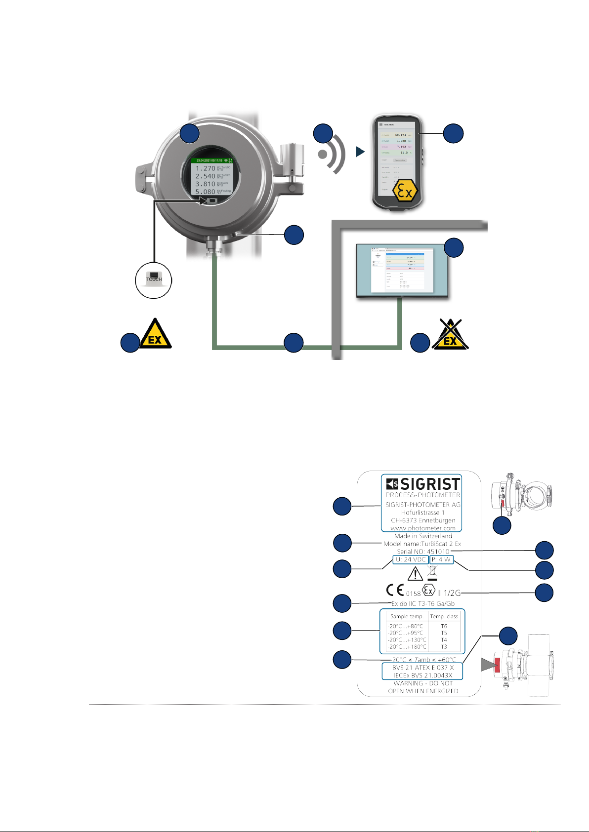
(1) Explosive area (2) TurBiScat 2 Ex
(3) WLAN connection (4) WLAN input device explosion tested
(5) Operating device or control system (6) Non explosive area
(7) Connecting cable explosion-protected (8) Earth conductor terminal
4.2 Nameplate
(1) Manufacturer
(2) Device type
(3) Serial number
(4) U: Service voltage
(5) P: Power
(6) Conformity information
(7) Protection class
(8) Temperature classes
(9) Certificates
(10) Ambient temperature
(11) Integrated communication module and pro-
duction year
1
2
4
3
5
6
7
89
10
11

Device data
10 / 62
4.3 Scope of supply and accessory parts
Please refer to the sales documents for the detailed scope of supply.
Standard scope of supply
Qty Designation Variant View
1 TurBiScat 2 Ex VARINLINE® connection
Flange connection
1 Blanking plate with cone and O-ring
FPM
VARINLINE® connection
1 Special measuring cell Flange connection
1 Control unit VARINLINE® connection
Flange connection
1 Brief instruction
Accessories
Art. no. Qty Designation Variant View
122105 1 Cooling unit
1 VARINLINE® housing
4.4 Specification sheet
Photometer Values
Measuring principle 90°/ 25° scattered light measurement at 650 nm (optional colour mea-
surement at 430 nm)
Measuring range 0 ... 4000 NTU turbidity
Measuring ranges Arbitrarily configurable
Wavelength 650 nm
Resolution 0.001 NTU turbidity

Device data
11 / 62
Photometer Values
Reproducibility (2 devices calibrated
with the same formazine)
NTU 90° 25°
0 ... 8 ±8 mNTU resp.
±1%
±8 mNTU resp.
±1%
8 ... 400 ±2% ±3%
400 ... 4000 ±10% ±10%
Linearity ± 0.5% of full scale in the range of 0 ... 8 NTU turbidity
Explosion protection type / tempera-
ture class
Ex db IIC T3/T4/T5/T6 Ga/Gb, temperature class depending on medium
temperature:
-20 … +80°C = T6
-20 … +95°C = T5
-20 … +130°C = T4
-20 … +180°C = T3
Ambient humidity 0 ... 100 % relative humidity
Ambient temperature -20 … +60°C
Medium temperature -20 … +180°C
Cooling depends on the maximum medium temperature (Tmed.) as well
as on the ambient temperature (Tenv.). The shaded area (X) indicates
the temperatures above which cooling by means of an optional cooling
ring is required. The flow must be at least 0.2 l/min. at a coolant tempera-
ture of max. 20 °C.
X
Max. pressure TurBiScat 2 Ex (window insert): 2 MPa (20 bar) at max. 180 °C.
VARINLINE® connection with blanking plate (art. no.: 122037): Note
specification.
Flange connection with special measuring cell: 2 MPa (20 bar) at max.
180 °C.
Service voltage 24 VDC ± 10 %
Protection class IP 66
Warm-up time < 3 min
Repeatability (2 measurements with
1 device)
0.001 NTU turbidity resp. ±0.25% of full scale value
Temperature stability < -0.15%K-1 of full scale value
Reaction time < 2 s (step response)
Colour measurement measuring
range (optional)
0 ... 200 E/m colour
Smallest measuring range 0 ... 20 E/m colour
Reproducibility ± 1.2 E/m colour
Repeatability ± 0.8 E/m colour
Material
l
Housing: Stainless steel 1.4462/ 1.4404/ borosilicate glass
l
Window: Sapphire
l
Parts in contact with medium: Hastelloy C-22 (2.4602)
l
VARINLINE® connection/ special measuring cell: Stainless steel 1.4404

Device data
12 / 62
Photometer Values
Dimension Ø 134.5 x 139 mm
Tube connections
l
VARINLINE® connection: DN 40 ... DN 150, 1 1/2" ... 6"
l
Flange connection with special measuring cell:
Ø 88.9 x 82.5 mm weld spigot
Weight 4.7 kg
Protection class IP 66
Display
l
Display: ¼ VGA with proximity sensor
l
Resolution: 320x240 pixels with 2.4" diagonal
WLAN module WLAN according to IEEE 802.11 b/g/n
Possible communication modules
Module Values
EG_IO: 6 configurable inputs/out-
puts
l
Max. 2 digital inputs: 5 ... 28VDC
l
Max. 4 digital outputs: High-side switch max. 20mA
l
Max. 4 power output terminals: 0/4 ... 20mA, max. 700ohm
EG_POE: Ethernet LAN connection
with Power over Ethernet
l
Ethernet according to 10/100BaseT
l
POE according to 802.3af, class 0

Mounting
13 / 62
5 Mounting
5.1 Requirements
For the mounting of the photometer and its additional components, the detailed dimension drawings must be ob-
served. The following provisions apply to the applications.
The photometer must be installed in the line at least 2 m away from sight glass or other sources of interfering
light.
Incorrect mounting may result in the formation of de-
posits or accumulation of air bubbles. The devices must
not be mounted standing (upwards) or hanging (down-
wards).
The photometer can be mounted with a standardised in-
line housing or a flange connection with a special mea-
suring cell, both in horizontal and vertical process lines.
In the vertical fitting position, the cable penetration must
point downwards. For horizontal fitting, the cable pene-
tration is on the side.
5.2 Installation on VARINLINE®connector
u
Mount the photometer (1) including seal (7) with
clamp ring (6) on the VARINLINE® connector.
u
Ensure that the groove (2) points in the flow direction.
u
Mount the blanking plate (3), including seal(4) with
clamp ring (5) on the VARINLINE® connector.
2
6
1
3
5
4
7
5.3 Fitting with flange connection
u
Fit the special measuring cell (3) in the process line
according to the dimension drawing.
u
Fasten the photometer (1) crosswise to the special
measuring cell(3) with 4 screws (4) .
u
Tighten the screws (4) (tightening torque min. 30 Nm,
max. 35 Nm).
u
Ensure that the groove (2) points in the flow direction.
13
4
2

Mounting
14 / 62
5.4 Connecting the cooling unit
Use commercially available silicone hoses (interior diameter 6 mm) for the cooling unit.
u
Ensure coolant flow from bottom to top.
u
Ensure a flow rate of min. 0.2 l/min.
u
Mount coolant supply line to the inlet (1) .
u
Mount coolant return line to the outlet (2) .
u
Open the coolant supply line and check for tightness.
1
2

Electrical installation
15 / 62
6 Electrical installation
DANGER
Danger due to improper connection of the operating voltage.
Improper connection of the electrical service voltage can be life-threatening. The system can also be damaged in
the process.
u
Connection must be carried out by a specialist in accordance with local regulations.
u
Install a disconnecting device near the power supply to disconnect the device from the mains. The discon-
necting device should be easily accessible and labelled.
u
It is mandatory to connect the protective earth conductor.
6.1 Requirements
Carry out the installation in the explosion hazard area in accordance with EN 60079-14 and observe the follow-
ing:
u
Do not shorten the supplied cable.
u
Install an explosion-proof electrical enclosure/disconnection device.
u
Without an explosion-proof electrical enclosure/disconnection device, run cable into explosion-proof room and
connect there.
u
Connect the shielding of the conducting cable.
6.2 Photometer connection
The shielding of the 8-pole conducting cable is connected to the housing on the device manufacturer side. The
function configuration of the individual strands depends on the installed communication module (Nameplate
[}9]).
Colour code
Abbrevia-
tion
Colour Abbrevia-
tion
Colour
wh/bn White-brown wh/og White-orange
bn Brown og Orange
wh/gn White-green wh/bu White-blue
gn Green bu Blue
EG_IO:
Cable strands wh/bn bn wh/gn gn wh/og og wh/bu bu
Function GND 24V IO1 IO2 IO3 IO4 IO5 IO6
RS485 Modbus RTU * A B
Digital input 5-28 VDC x x
Digital output "High Side Switch"
max. 20 mA
xxxx
Power output terminal 0/4...20
max. 700 Ω
xxxx
* with or without 120 Ω termination (configurable)
EG_POE:
The sensor is powered via "Power over Ethernet" (POE) (802.3af, class 0). The cable has the following charac-
teristics: Cat. 6, STP, AWG 24/7, TIA-568A. The module supports Fast Ethernet 100Base_T. Various services
are available (web server, Modbus TCP, etc.)

Electrical installation
16 / 62
Cable
strands
wh/gn gn wh/og og wh/bu bu wh/bn bn
Function 10/100BaseT TX+ TX- RX+ RX-
POE Mode A DC- DC+
POE Mode B DC+ DC-
Operation
17 / 62
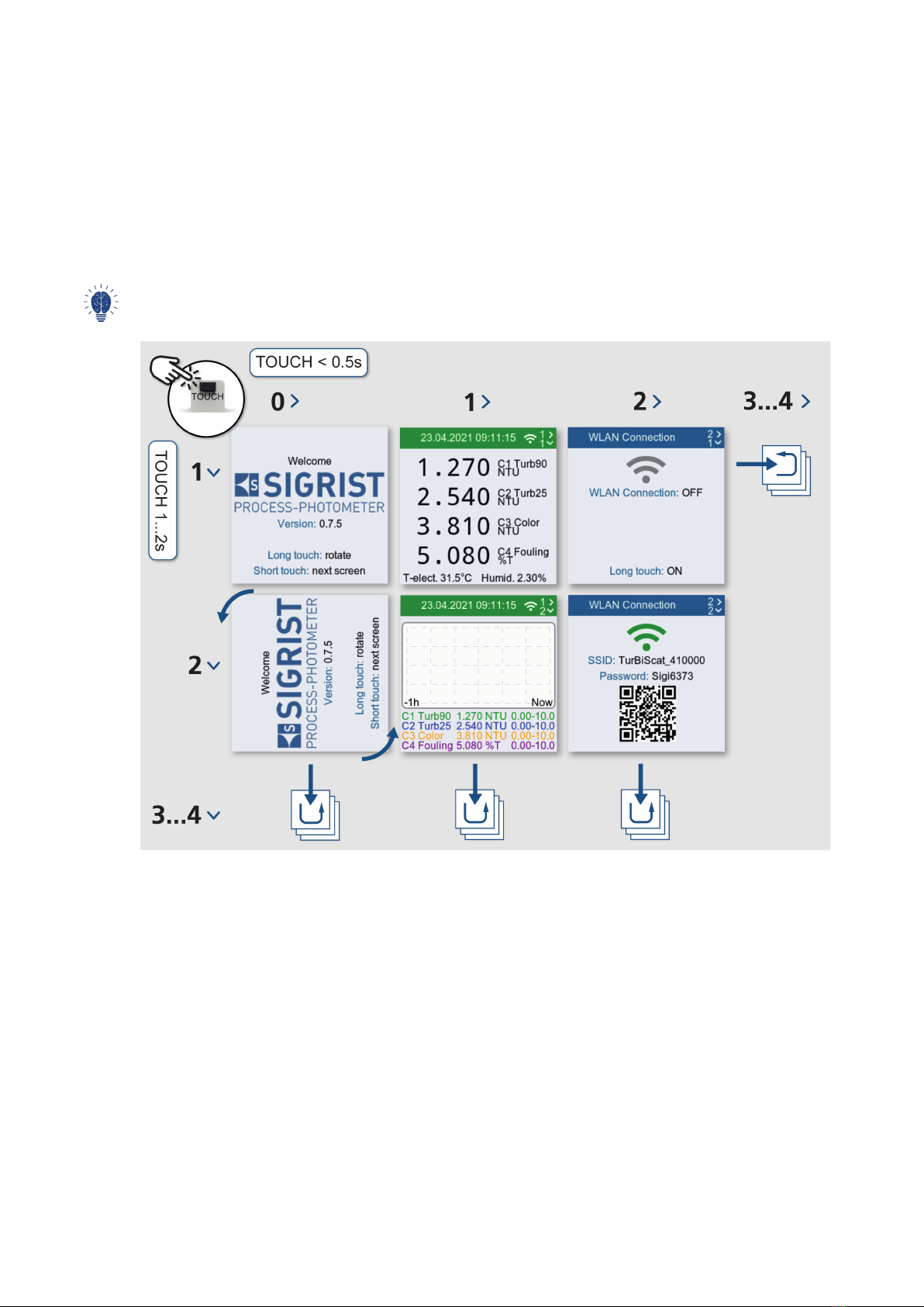
7 Operation
The device can be operated via the proximity sensor (TOUCH), with the finger on the device display or with WiFi-
capable devices.
7.1 Display
7.1.1 Operating elements
You can switch between the different menu items by touching them.
l
Short touch (<0.5s): navigate between menus
l
Long touch (1...2s): Navigate within a menu
For the input to be recognized, the finger must be lifted at least 5 cm after the touch. Without activity, the display
changes to the measurement monitor after one minute.
Operation
18 / 62
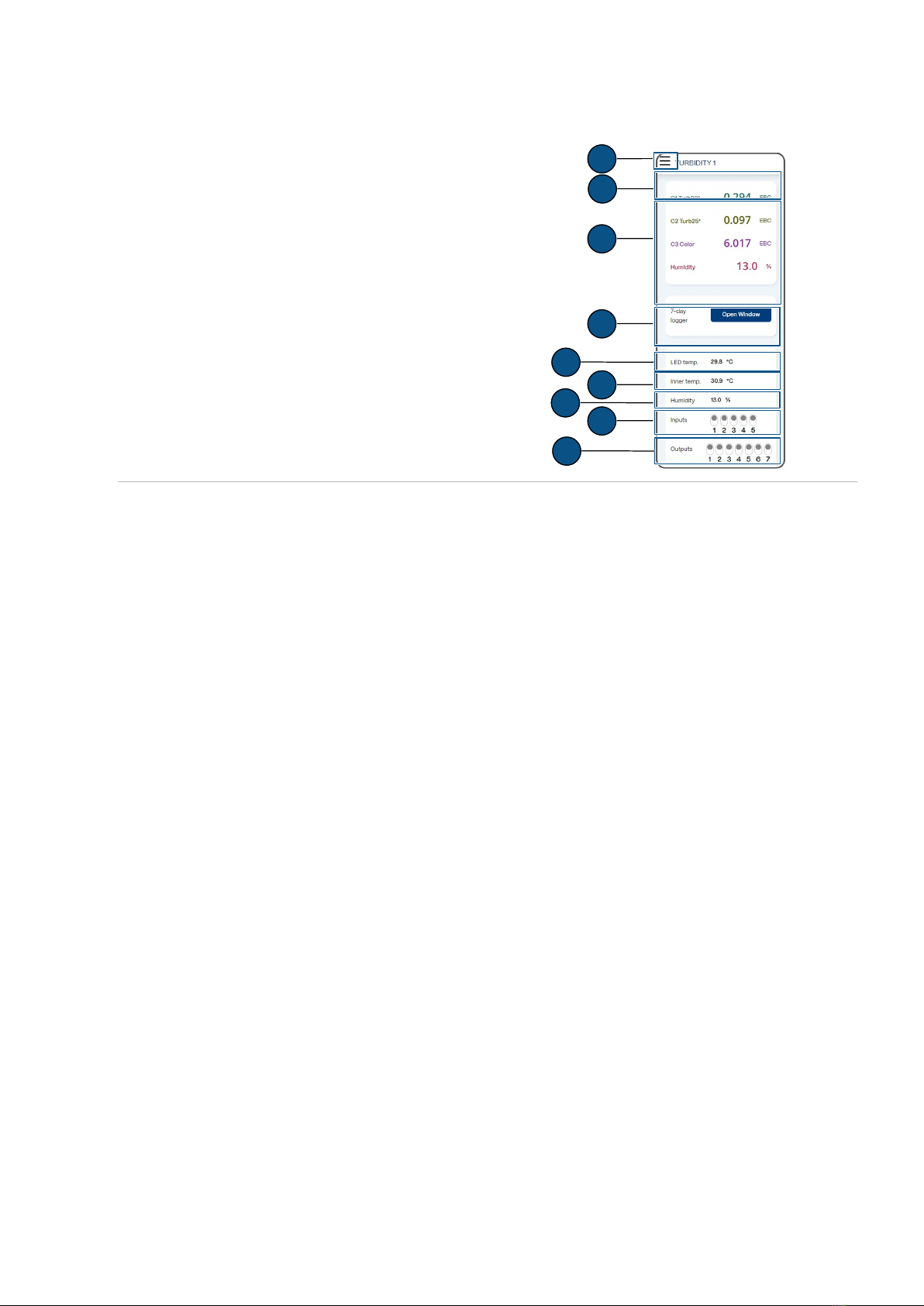
7.2 Operation SIGRIST-Webinterface
7.2.1 SIGRIST-Webinterface
(1) Menu settings
(2) Status
(3) Current measured values
(4) 7-day logger diagram
(5) LED temperature
(6) Sensor internal temperature
(7) Sensor humidity
(8) Status inputs
(9) Status outputs
1
3
4
6
8
2
5
7
9

Commissioning
19 / 62
8 Commissioning
u
Ensure correct mounting and electrical installation.
u
Establish service voltage.
w
Start screen appears.
Rotate display if necessary
Display can only be rotated during start display. Without
action, display changes to measuring mode after 15
seconds.
u
Touch the proximity sensor for a long time.
w
Display rotates by 90°.
u
Repeat until the display is in the correct position.
u
Touch the proximity sensor briefly.
w
The display changes to the next menu.
Activating the WLAN
u
Navigate to «WLAN connection».
u
Touch the proximity sensor for a long time.
w
WLAN is activated.
Connect mobile device
NOTICE!
No VPN connection must be active on the mobile de-
vice.
u
Connect the mobile device to the WLAN with the QR
code.
u
Confirm the warning "No Internet connection" with
[OK] .
w
The mobile device is connected.
Alternative:
u
Connect the mobile device to the WLAN.
u
Select the displayed SSID.
u
Enter the displayed access code.
u
Confirm the warning "No Internet connection" with
[OK] .
w
The mobile device is connected.

Commissioning
20 / 62
Sigrist-Webinterface Open
u
Access URL with QR code.
Alternative:
u
Open browser (e.g. Chrome, Safari).
u
Enter the displayed URL (192.168.10.1).
w
Login screen appears.
Log in to SIGRIST-Webinterface
u
Log in without password.
Recommendation: Secure access to the SIGRIST-We-
binterface with a password.
Other manuals for TurBiScat 2 Ex
2
Table of contents
Other SIGRIST Industrial Equipment manuals

Popular Industrial Equipment manuals by other brands

Teledyne
Teledyne MA2709A quick start guide

Tektronix
Tektronix DAS 92DM930 instruction manual

Nexen
Nexen AIR CHAMP BC425A user manual

Hugh Crane
Hugh Crane COMMANDO DUSTGUARD operating & maintenance manual

Trumpf
Trumpf TruHeat HF 1000 Series operating instructions

Stearns
Stearns 55,00 Series Wiring instructions


Eaton
Eaton EU1E-SWD Series Instruction leaflet

SEW-Eurodrive
SEW-Eurodrive MOVIMOT CM3C DAC Series operating instructions

Rodix
Rodix FEEDER CUBE FC-40 Plus Series Adjustments and Set Up

Komet
Komet 555 Instructions for use

Fröling
Fröling FBR-G Installation and operating instructions

Manntek
Manntek DAC operating manual