Siko IF09P/1 User manual


IF09P/1
Deutsch
IF09P/1 · Datum 26.08.2019 · Art. Nr. 82491 · Änd. Stand 209/19
2
Inhaltsverzeichnis
1 Dokumentation . . . . . . . . . . . . . . . . . . . . 3
2 Sicherheitshinweise . . . . . . . . . . . . . . . . . . 3
2.1 Bestimmungsgemäße Verwendung . . . . . . . . . . . 3
2.2 Kennzeichnung von Gefahren und Hinweisen . . . . . . 3
2.3 Zielgruppe . . . . . . . . . . . . . . . . . . . . 4
2.4 Grundlegende Sicherheitshinweise . . . . . . . . . . . 5
3 Identifikation . . . . . . . . . . . . . . . . . . . . . 5
4 Installation . . . . . . . . . . . . . . . . . . . . . . 5
4.1 Mechanische Montage . . . . . . . . . . . . . . . . 5
4.2 Elektrische Installation . . . . . . . . . . . . . . . 6
5 Transport, Lagerung, Wartung und Entsorgung . . . . . . . 8
6 Technische Daten . . . . . . . . . . . . . . . . . . . 8

IF09P/1
Dokumentation Deutsch
IF09P/1 · Datum 26.08.2019 · Art. Nr. 82491 · Änd. Stand 209/19
3
1 Dokumentation
Zu diesem Produkt gibt es folgende Dokumente:
• Datenblatt beschreibt die technischen Daten, die Abmaße, die
Anschlussbelegungen, das Zubehör und den Bestellschlüssel.
• Montageanleitung beschreibt die mechanische und die elektrische
Montage mit allen sicherheitsrelevanten Bedingungen und den dazu-
gehörigen technischen Vorgaben.
• Benutzerhandbuch zur Inbetriebnahme.
Diese Dokumente sind auch unter "http://www.siko-global.com/p/
if09p-1" zu finden.
2 Sicherheitshinweise
2.1 Bestimmungsgemäße Verwendung
Die Aufgabe des Profibus-Gateways IF09P/1 besteht darin, SIKO-Positi-
onswertgeber, welche über das Schnittstellenprotokoll SIKONETZ3 bzw.
SIKONETZ4 verfügen, an den PROFIBUS-DP anzukoppeln. Ein gemeinsa-
mer Anschluss von SIKONETZ3- und SIKONETZ4-Geräten ist nicht möglich.
Die Auswahl der beiden Schnittstellenprotokolle, der PROFIBUS-Teilneh-
meradresse sowie diverser Diagnosefunktionen erfolgt über die Tastatur
am IF09P/1.
1. Beachten Sie alle Sicherheitshinweise in dieser Anleitung.
2. Lesen Sie alle beigefügten Dokumentationen auf der CD.
3. Eigenmächtige Umbauten und Veränderungen an dem Interface sind
verboten.
4. Die vorgeschriebenen Betriebs- und Installationsbedingungen sind
einzuhalten.
5. Das Interface darf nur innerhalb der technischen Daten und der ange-
gebenen Grenzen betrieben werden (siehe Kapitel 6).
2.2 Kennzeichnung von Gefahren und Hinweisen
Sicherheitshinweise bestehen aus dem Signalzeichen und einem Signal-
wort.
Gefahrenklassen
Unmittelbare Gefährdungen, die zu schweren irreversiblen Körperverlet-
zungen mit Todesfolge, Sachschäden oder ungeplanten Gerätereaktionen
führen können, sofern Sie die gegebenen Anweisungen missachten.
GEFAHR

IF09P/1
Sicherheitshinweise Deutsch
IF09P/1 · Datum 26.08.2019 · Art. Nr. 82491 · Änd. Stand 209/19
4
Gefährdungen, die zu schweren Körperverletzungen, Sachschäden oder
ungeplanten Gerätereaktionen führen können, sofern Sie die gegebenen
Anweisungen missachten.
Gefährdungen, die zu leichten Verletzungen, Sachschäden oder ungeplan-
ten Gerätereaktionen führen können, sofern Sie die gegebenen Anweisun-
gen missachten.
Wichtige Betriebshinweise, die die Bedienung erleichtern oder die bei
Nichtbeachtung zu ungeplanten Gerätereaktionen führen können und
somit möglicherweise zu Sachschäden führen können.
Signalzeichen
2.3 Zielgruppe
Montageanleitung und Benutzerhandbuch wenden sich an das Projek-
tierungs-, Inbetriebnahme- und Montagepersonal von Anlagen- oder
Maschinenherstellern, das über besondere Kenntnisse innerhalb der
Antriebstechnik verfügt. Dieser Personenkreis benötigt fundierte Kennt-
nisse über die notwendigen Anschlüsse eines Interfaces und deren Integ-
ration in die komplette Maschinenanlage.
Nicht ausreichend qualifiziertes Personal
Personenschäden, schwere Schäden an Maschine und Interface werden
durch nicht ausreichend qualifiziertes Personal verursacht.
`Projektierung, Inbetriebnahme, Montage und Wartung nur durch
geschultes Fachpersonal.
`Dieses Personal muss in der Lage sein, Gefahren, welche durch die
mechanische, elektrische oder elektronische Ausrüstung verursacht
werden können, zu erkennen.
Qualifiziertes Personal
sind Personen, die
• als Projektierungspersonal mit den Sicherheitsrichtlinien der Elektro-
und Automatisierungstechnik vertraut sind;
• als Inbetriebnahme- und Monatagepersonal berechtigt sind, Strom-
kreise und Geräte/Systeme gemäß den Standards der Sicherheitstech-
nik in Betrieb zu nehmen, zu erden und zu kennzeichnen.
WARNUNG
VORSICHT
ACHTUNG
WARNUNG
IF09P/1
Identifikation Deutsch
IF09P/1 · Datum 26.08.2019 · Art. Nr. 82491 · Änd. Stand 209/19
5
2.4 Grundlegende Sicherheitshinweise
Explosionsgefahr
`Interface nicht in explosionsgefährdeten Zonen einsetzen.
3 Identifikation
Das Typenschild zeigt den Gerätetyp mit Variantennummer. Die Lieferpa-
piere ordnen jeder Variantennummer eine detaillierte Bestellbezeichnung
zu.
z. B. IF09P/1-0023
Varianten-Nr.
Geräte-Typ
4 Installation
4.1 Mechanische Montage
Die Montage darf nur gemäß der angegebenen IP-Schutzart vorgenommen
werden. Das System muss ggfs. zusätzlich gegen schädliche Umweltein-
flüsse, wie z. B. Spritzwasser, Staub, Schläge, Temperatur geschützt werden.
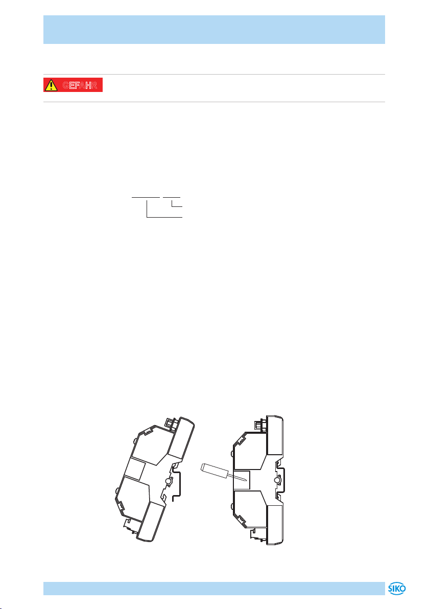
Das IF09P/1 ist zum Anbau an eine Hutschiene 35x7.5 nach DIN 50022
vorgesehen.
Gerät in die Schiene einhängen, ggf. Klemmschrauben so weit lösen, dass
das Gerät einwandfrei an der Schiene anliegt.
Klemmschrauben mit Schlitz-Schraubendreher Größe 0.8x4 oder Kreuz-
schlitz Größe 1 festziehen.
Abb. 1: Einbau
GEFAHR

IF09P/1
Installation Deutsch
IF09P/1 · Datum 26.08.2019 · Art. Nr. 82491 · Änd. Stand 209/19
6
4.2 Elektrische Installation
Zerstörung von Anlagenteilen und Verlust der Steuerungskontrolle
`Bei Verwendung in Antriebssystemen sind zusätzliche Sicherheitsab-
schaltungen z. B. durch Endlagenschalter oder andere Verriegelungen
vorzusehen.
`Alle Leitungen für das Interface müssen geschirmt sein.
`Elektrische Verbindungen nicht unter Spannung anschließen oder lösen.
`Verdrahtungsarbeiten spannungslos durchführen.
`Litzen mit geeigneten Aderendhülsen versehen.
`Vor dem Einschalten sind alle Leitungsanschlüsse und Steckverbindun-
gen zu überprüfen.
`Betriebsspannung gemeinsam mit der Folgeelektronik (z. B. Steue-
rung) einschalten.
`PE-Verbindung mit 2.5 ... 4mm² über PE-Anschluss.
`Zur Datenübertragung sind Kabellängen bis max. 200m möglich.
Alle Anschlüsse sind prinzipiell gegen äußere Störeinflüsse geschützt.
Der Einsatzort ist so zu wählen, dass induktive oder kapazitive Störungen
nicht auf das Interface oder dessen Anschlussleitungen einwirken können.
Das System in möglichst großem Abstand von Leitungen einbauen, die mit
Störungen belastet sind. Gegebenenfalls sind zusätzliche Maßnahmen,
wie Schirmbleche oder metallisierte Gehäuse vorzusehen. Schützspulen
müssen mit Funkenlöschgliedern beschaltet sein.
Zulässige Leistungsaufnahme
Die Versorgung für das Interface ist ausreichend zu dimensionieren. Die
Spannungswerte sind abhängig von der Geräteausführung und sind den
technischen Daten in Kapitel 6zu entnehmen.
4 6
3
5 1
2
5
9
5
6
5
1
11
9
3
6
2
6 9
1
X4 X3
X5 X1
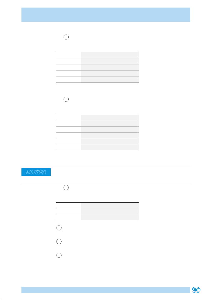
Abb. 2: Anschluss
1Anschluss Sensor
2Anschluss Profibus
3Betriebsspannung
4LED Data Exchange
5LED ERROR
6LED PowerOn
WARNUNG
ACHTUNG
ACHTUNG
IF09P/1
Installation Deutsch
IF09P/1 · Datum 26.08.2019 · Art. Nr. 82491 · Änd. Stand 209/19
7
Anschlussbelegung Sensor X3 bzw. X4
• 19 pol. D-Sub Buchsenkontakt (siehe Abb. 2).
PIN Belegung
1 +UB (max. 0.75A belastbar!)
3DÜA
5 GND
8 DÜB
2, 3, 6, 7, 9 nc
Anschlussbelegung Profibus X5
• 29 pol. D-Sub Buchsenkontakt (siehe Abb. 2).
PIN Belegung
3 B-Line
4 RTS
5 2M
6 2P5
8 A-Line
1, 2, 7, 9 nc
Anschlussbelegung Betriebsspannung X1
Aus EMV-technischen Gründen ist es erforderlich, über die zusätzliche PE-
Klemme eine niederimpedante Verbindung zum Potentialausgleichsystem
herzustellen.
• 33 pol. Stecker Stiftkontakt (siehe Abb. 2).
PIN Belegung
1 PE
2 0V
3 +24VDC ±20%
4LED PowerOn (grün): zeigt an, dass die interne Versorgungsspannung
im tolerierbaren Bereich liegt.
5LED DE (gelb): zeigt den Zustand "Data Exchange" auf dem Profibus
an.
6LED Error (rot): zeigt Fehler in der Datenübertragung an (siehe Benut-
zerhandbuch).
ACHTUNG

IF09P/1
Transport, Lagerung, Wartung und Entsorgung Deutsch
IF09P/1 · Datum 26.08.2019 · Art. Nr. 82491 · Änd. Stand 209/19
8
Auf dem fünfstelligen LED-Display, welches sich unter der transparenten
Haube befindet, werden im Fehlerfall zusätzlich Hinweise auf den/ die feh-
lerverursachenden Geber angezeigt. Nach Abnahme der Haube ist die Tas-
tatur zugänglich. Diese dient sowohl zur Eingabe verschiedener Parame-
terwerte des IF09P/1, als auch zur Diagnose der angeschlossenen Geber.
5 Transport, Lagerung, Wartung und Entsorgung
Transport und Lagerung
Interface sorgfältig behandeln, transportieren und lagern. Hierzu sind
folgende Punkte zu beachten:
• Interface in der ungeöneten Originalverpackung transportieren und/
oder lagern.
• Interface vor schädlichen physikalischen Einflüssen wie Staub, Hitze
und Feuchtigkeit schützen.
• Anschlüsse weder durch mechanische noch durch thermische Einflüsse
beschädigen.
• Vor Montage ist das Interface auf Transportschäden zu untersuchen.
Beschädigtes Interface nicht einbauen.
Wartung
Bei korrektem Einbau nach Kapitel 4ist das Interface wartungsfrei.
Entsorgung
Die elektronischen Bauteile des Interface enthalten umweltschädigende
Stoe und sind zugleich Wertstoträger. Das Interface muss deshalb nach
seiner endgültigen Stilllegung einem Recycling zugeführt werden. Die
Umweltrichtlinien des jeweiligen Landes müssen hierzu beachtet werden.
6 Technische Daten
Mechanische Daten Ergänzung
Gehäuse Kunststo Hutschiene, EN 50022
Elektrische Daten Ergänzung
Betriebsspannung 24VDC ±20%
Leistungsaufnahme <1.3W
Geberversorgung ≤700mA belastbar

IF09P/1
Technische Daten Deutsch
IF09P/1 · Datum 26.08.2019 · Art. Nr. 82491 · Änd. Stand 209/19
9
Elektrische Daten Ergänzung
Parameterspeicher 106Zyklen gilt auch für Kalibriervorgänge
Anzeige/Anzeigenbereich 5-stellig, LED 7-Segment,
~7.6mm hoch
Baudrate 115.2kBit/s Geberseite SIKONETZ4
19.2kBit/s Geberseite SIKONETZ3
9.6kBit/s … 12MBit/s ProfiBus
Umgebungsbedingungen Ergänzung
Umgebungstemperatur 0 … 50°C
relative Luftfeuchtigkeit Betauung nicht zulässig
Schutzart IP30

IF09P/1
English
IF09P/1 · Date 26.08.2019 · Art. No. 82491 · Mod. status 209/19
10
Table of contents
1 Documentation . . . . . . . . . . . . . . . . . . . 11
2 Safety information . . . . . . . . . . . . . . . . . . 11
2.1 Intended use . . . . . . . . . . . . . . . . . . . 11
2.2 Identification of dangers and notes . . . . . . . . . 11
2.3 Target group . . . . . . . . . . . . . . . . . . . 12
2.4 Basic safety information . . . . . . . . . . . . . . 12
3 Identification . . . . . . . . . . . . . . . . . . . . 13
4 Installation . . . . . . . . . . . . . . . . . . . . . 13
4.1 Mechanical mounting . . . . . . . . . . . . . . . 13
4.2 Electrical installation . . . . . . . . . . . . . . . 14
5 Transport, Storage, Maintenance and Disposal . . . . . . 16
6 Technical data . . . . . . . . . . . . . . . . . . . . 16

IF09P/1
Documentation English
IF09P/1 · Date 26.08.2019 · Art. No. 82491 · Mod. status 209/19
11
1 Documentation
The following documents describe this product:
• The data sheet describes the technical data, the dimensions, the pin
assignments, the accessories and the order key.
• The mounting instructions describe the mechanical and electrical
installation including all safety-relevant requirements and the associ-
ated technical specifications.
• The user manual for commissioning.
These documents can also be downloaded at "http://www.siko-global.
com/p/if09p-1".
2 Safety information
2.1 Intended use
The task of Profibus-Gateway IF09P/1 is the linkage of SIKO position
encoders with SIKONETZ3 or SIKONETZ4 protocol to a Profibus-DP. SIKO-
NETZ3 and SIKONETZ4 cannot share, however one common connection. The
two interface protocols, the PROFIBUS station address as well as various
diagnostic functions are selected by means of the keyboard of the IF09P/1.
1. Observe all safety instructions contained herein.
2. Read all documents provided on the CD.
3. Arbitrary modifications and changes to this interface are forbidden.
4. Observe the prescribed operating and installation conditions.
5. Operate the interface exclusively within the scope of technical data
and the specified limits (see chapter 6).
2.2 Identification of dangers and notes
Safety notes consist of the signal symbol and a signal word.
Danger classes
Immediate danger that may cause irreversible bodily harm resulting in
death, property damage or unplanned device reactions if you disregard
the instructions given.
Danger that may cause serious bodily harm, property damage or
unplanned device reactions if you disregard the instructions given.
DANGER
WARNING
IF09P/1
Safety information English
IF09P/1 · Date 26.08.2019 · Art. No. 82491 · Mod. status 209/19
12
Danger that may cause minor injury, property damage or unplanned device
reactions if you disregard the instructions given.
Important operating information that may facilitate operation or many
cause unplanned device reactions if disregarded including possible prop-
erty damage.
Signal symbols
2.3 Target group
Installation instructions and User manual are intended for the configura-
tion, commissioning and mounting personnel of plant or machine manu-
facturers who possess special expertise in drive technology. This group of
operators needs profound knowledge of an interface's necessary connec-
tions and its integration into a complete machinery.
Insuciently qualified personnel
Insuciently qualified personnel cause personal injury, serious damage to
machinery or interface.
`Configuration, commissioning, mounting and maintenance by trained
expert personnel only.
`This personnel must be able to recognize dangers that might arise
from mechanical, electrical or electronic equipment.
Qualified personnel are persons who
• are familiar with the safety guidelines of the electrical and automation
technologies when performing configuration tasks;
• are authorized to commission, earth and label circuits and devices/
systems in accordance with the safety standards.
2.4 Basic safety information
Danger of explosion
`Do not use the interface in explosive zones.
CAUTION
NOTICE
WARNING
DANGER

IF09P/1
Identification English
IF09P/1 · Date 26.08.2019 · Art. No. 82491 · Mod. status 209/19
13
3 Identification
Please check the particular type of unit and type number from the identifi-
cation plate. Type number and the corresponding version are indicated in
the delivery documentation.
e. g. IF09P/1-0023
variant number
type of unit
4 Installation
4.1 Mechanical mounting
For mounting, the degree of protection specified must be observed. If nec-
essary, protect the unit against environmental influences such as sprayed
water, dust, knocks, extreme temperatures.
IF09P/1 has been designed for mounting on standrad rails 35x7.5 accord.
to DIN 50022.
For mounting snap the retainer onto the rail and ensure that the lock is at
the device's underside. For dismounting, the lock is pushed downward.
Tighten the clamping screws with a slotted screwdriver size 0.8x4 or a
cross recess size 1.
Fig. 1: Installation

IF09P/1
Installation English
IF09P/1 · Date 26.08.2019 · Art. No. 82491 · Mod. status 209/19
14
4.2 Electrical installation
Destruction of parts of equipment and loss of regulation control
`If the unit is used in combination with drive systems, additional safety
protection must be used (e. g. limit switches or other interlocking sys-
tems).
`All lines for connecting the interface must be shielded.
`Never wire or disconnect electrical connections while they are live.
`Perform wiring work in the de-energized state only.
`Use strands with suitable ferrules.
`Check all lines and plug connections before switching on the device.
`Switch on operating voltage together with the downstream electronic
unit (e. g., control unit).
`PE-connection with 2.5 ... 4mm² via PE-connector.
`With data transmission max. allowable cable length is 200m.
Basically, all connections are protected against external interference.
Choose a place of operation that excludes inductive or capacitive interfer-
ence influences on the interface. When mounting the system keep a max-
imum possible distance from lines loaded with interference. If necessary,
provide additional installations including screening shields or metallized
housings. Contactor coils must be linked with spark suppression.
Admissible power input
Supply for the interface shall be sized suciently. The voltage values are
a function of the device design and can be referred to in the technical data
in chapter 6.
4 6
3
5 1
2
5
9
5
6
5
1
11
9
3
6
2
6 9
1
X4 X3
X5 X1
Fig. 2: Connection
1Connection sensor
2Connection Profibus
3Operating voltage
4LED Data Exchange
5LED ERROR
6LED PowerOn
WARNING
NOTICE
NOTICE

IF09P/1
Installation English
IF09P/1 · Date 26.08.2019 · Art. No. 82491 · Mod. status 209/19
15
Pin assignment Sensor X3 resp. X4
• 19 pole D-Sub socket contact (see Fig. 2).
PIN Designation
1 +UB (max. 0.75A load!)
3DÜA
5 GND
8 DÜB
2, 3, 6, 7, 9 nc
Pin assignment Profibus X5
• 29 pole D-Sub socket contact (see Fig. 2).
PIN Designation
3 B-Line
4 RTS
5 2M
6 2P5
8 A-Line
1, 2, 7, 9 nc
Pin assignment Operating voltage X1
To be EMC-compatible it is necessary to establish a low-impedance connec-
tion to the potential matching system via the additional PE terminal.
• 33 pole plug plug pin (see Fig. 2).
PIN Designation
1 PE
2 0V
3 +24VDC ±20%
4LED Power Good (green): indicates that the internal supply voltage is
within the tolerable range.
5LED DE (yellow): shows the status "Data Exchange" on the profibus.
6LED Error (red): indicates errors of data transmission (see also user
manual).
NOTICE

IF09P/1
Transport, Storage, Maintenance and Disposal English
IF09P/1 · Date 26.08.2019 · Art. No. 82491 · Mod. status 209/19
16
In case of an error, information concerning the encoder(s) causing the
error is displayed on the five-digit LED display, which is below the trans-
parent hood. After removing the hood, the keyboard is accessible. It
serves both for putting in various parameter values of the IF09P/1 and for
diagnosing the encoders connected.
5 Transport, Storage, Maintenance and Disposal
Transport and storage
Handle, transport and store interface with care. Pay attention to the fol-
lowing points:
• Transport and / or store interface in the unopened original packaging.
• Protect interface from harmful physical influences including dust,
heat and humidity.
• Do not damage connections through mechanical or thermal impact.
• Prior to installation inspect the interface for transport damages. Do
not install damaged interface.
Maintenance
With correct installation according to chapter 4the interface requires no
maintenance.
Disposal
The interface's electronic components contain materials that are harmful
for the environment and are carriers of recyclable materials at the same
time. Therefore, the interface must be recycled after it has been taken out
of operation ultimately. Observe the environment protection guidelines of
your country.
6 Technical data
Mechanical data Additional information
Housing plastic top hat rail, EN 50022
Electrical data Additional information
Operating voltage 24VDC ±20%
Power input <1.3W
Encoder supply ≤700mA loadable
IF09P/1
Technical data English
IF09P/1 · Date 26.08.2019 · Art. No. 82491 · Mod. status 209/19
17
Electrical data Additional information
Parameter memory 106cycles also applies to calibration pro-
cedures
Display/display range 5-digit, LED 7-segment,
~7.6mm height
Baud rate 115.2kBit/s SIKONETZ4 encoder side
19.2kBit/s SIKONETZ3 encoder side
9.6kBit/s … 12MBit/s ProfiBus
Ambient conditions Additional information
Ambient temperature 0 … 50°C
Relative humidity condensation inadmissible
Protection category IP30

IF09P/1
18

IF09P/1 19

SIKO GmbH
Weihermattenweg 2
79256 Buchenbach
Telefon/Phone
+49 7661 394-0
Telefax/Fax
+49 7661 394-388
E-Mail
Internet
www.siko-global.com
Service
suppor[email protected]
Änderungen vorbehalten · Subject to technical alternations · 26.08.2019 · 209/19
Table of contents
Languages:
Other Siko Recording Equipment manuals


