Siko AG05 User manual

139/16
AG05
Actuator with RS485/SIKONETZ5 interface
User manual

AG05 Date: 15.06.2016 Art. No. 85677 Mod. status 139/16 Page 2 of 64
Table of contents
1General Information .................................................................................................. 4
1.1 Documentation ........................................................................................................4
2Block Diagram ........................................................................................................... 4
3Display and Control Keys............................................................................................ 5
3.1 General ...................................................................................................................5
3.2 LCD display..............................................................................................................5
3.3 LED displays ............................................................................................................5
4Functional Description ............................................................................................... 6
4.1 Control of the drive ..................................................................................................6
4.1.1 Value input ..........................................................................................................6
4.1.2 Value selection .....................................................................................................6
4.1.3 Operating modes...................................................................................................6
4.1.3.1 Positioning mode ..............................................................................................6
4.1.3.1.1 Loop positioning............................................................................................7
4.1.3.2 Inching operation..............................................................................................8
4.1.3.2.1 Inching mode 1 .............................................................................................8
4.1.3.2.2 Inching mode2 ..............................................................................................8
4.1.3.3 Rotational speed mode.......................................................................................9
4.1.4 Current limiting ....................................................................................................9
4.2 Manual control (stand-alone operation).....................................................................10
4.2.1 Start inching mode 2...........................................................................................10
4.2.2 Specifying the set point and starting the travel order...............................................10
4.2.2.1 Example: Starting positioning order to position 500 .............................................10
4.2.2.2 Example: Starting positioning order to position -500............................................10
4.3 Menu selection.......................................................................................................12
4.3.1 Changeable parameters ........................................................................................13
4.3.1.1 Bus parameters ...............................................................................................13
4.3.1.2 Positioning.....................................................................................................14
4.3.1.3 Actuator.........................................................................................................15
4.3.1.4 Limiting values ...............................................................................................16
4.3.1.5 Visualization...................................................................................................16
4.3.1.6 Options..........................................................................................................18
4.3.1.7 Controller parameters.......................................................................................19
4.3.2 Readable parameters ...........................................................................................19
4.3.3 Error memory......................................................................................................20
5Calibration.............................................................................................................. 21
6External gear........................................................................................................... 21
7Warnings / Errors..................................................................................................... 22
7.1 Warnings...............................................................................................................22

AG05 Date: 15.06.2016 Art. No. 85677 Mod. status 139/16 Page 3 of 64
7.2 Errors....................................................................................................................22
7.2.1 Error codes.........................................................................................................22
7.3 Input errors ...........................................................................................................23
8Parameter description.............................................................................................. 24
9Service Protocol....................................................................................................... 33
9.1 General .................................................................................................................33
9.2 System Status Word ................................................................................................33
9.2.1 Meaning of the bits.............................................................................................33
9.3 Service protocol commands list.................................................................................35
9.4 Error number encoding ............................................................................................45
9.5 Flow chart: Operating mode: Positioning mode ...........................................................46
9.6 Flow chart: Operating mode: Speed mode...................................................................47
10 Communication via SIKONETZ5 ................................................................................. 47
10.1 Interface...............................................................................................................47
10.2 Data exchange .......................................................................................................47
10.3 Telegram setup.......................................................................................................48
10.3.1 Command...........................................................................................................48
10.3.2 Node ID.............................................................................................................48
10.3.3 Parameter address...............................................................................................48
10.3.4 Control word ......................................................................................................48
10.3.5 Status word........................................................................................................48
10.3.6 Data..................................................................................................................48
10.3.7 Check sum..........................................................................................................49
10.4 Synchronization .....................................................................................................49
10.5 Error telegram........................................................................................................49
10.5.1 SIKONETZ5 error codes.........................................................................................50
10.6 Errors....................................................................................................................50
10.7 Communication monitoring ......................................................................................50
10.7.1 Bus Timeout.......................................................................................................50
10.7.2 Locking the programming mode ............................................................................51
10.8 Functional description of the control units.................................................................51
10.8.1 Control word: Positioning mode (master slave) ...................................................51
10.8.2 Status word: Positioning mode (slave master).....................................................52
10.8.3 Flow chart: Positioning mode................................................................................53
10.8.4 Control word Operating mode: Speed mode .............................................................54
10.8.5 Status word: Speed mode .....................................................................................54
10.8.6 Flow chart: Operating mode: Speed mode ...............................................................56
10.9 Parameterization via SIKONETZ5 ...............................................................................56
10.9.1 Example: Read parameter .....................................................................................63
10.9.2 Example: Write parameter.....................................................................................64

General Information
AG05 Date: 15.06.2016 Art. No. 85677 Mod. status 139/16 Page 4 of 64
1General Information
1.1 Documentation
The following documents are associated with this document:
The data sheet describes the technical data, the dimensions, the pin assignment, the
accessories and the order key.
The installation instructions describe the mechanical and electrical installation with all
safety-relevant conditions and the associated technical specifications.
The User manual for actuator commissioning and integration into a fieldbus system.
You can also download these documents at http://www.siko-global.com/p/ag05.
2Block Diagram
Fig. 1: Block diagram
Inverse-
polarity
protection
Mains
adapter
Control
Output stage
Motor
Encoder
Gear
Bus electronics
+UB
control
RS485
+UB
output
stage
Inverse-
polarity
protection
Verpol-
schutz
Battery
Display and Control Keys
AG05 Date: 15.06.2016 Art. No. 85677 Mod. status 139/16 Page 5 of 64
3Display and Control Keys
3.1 General
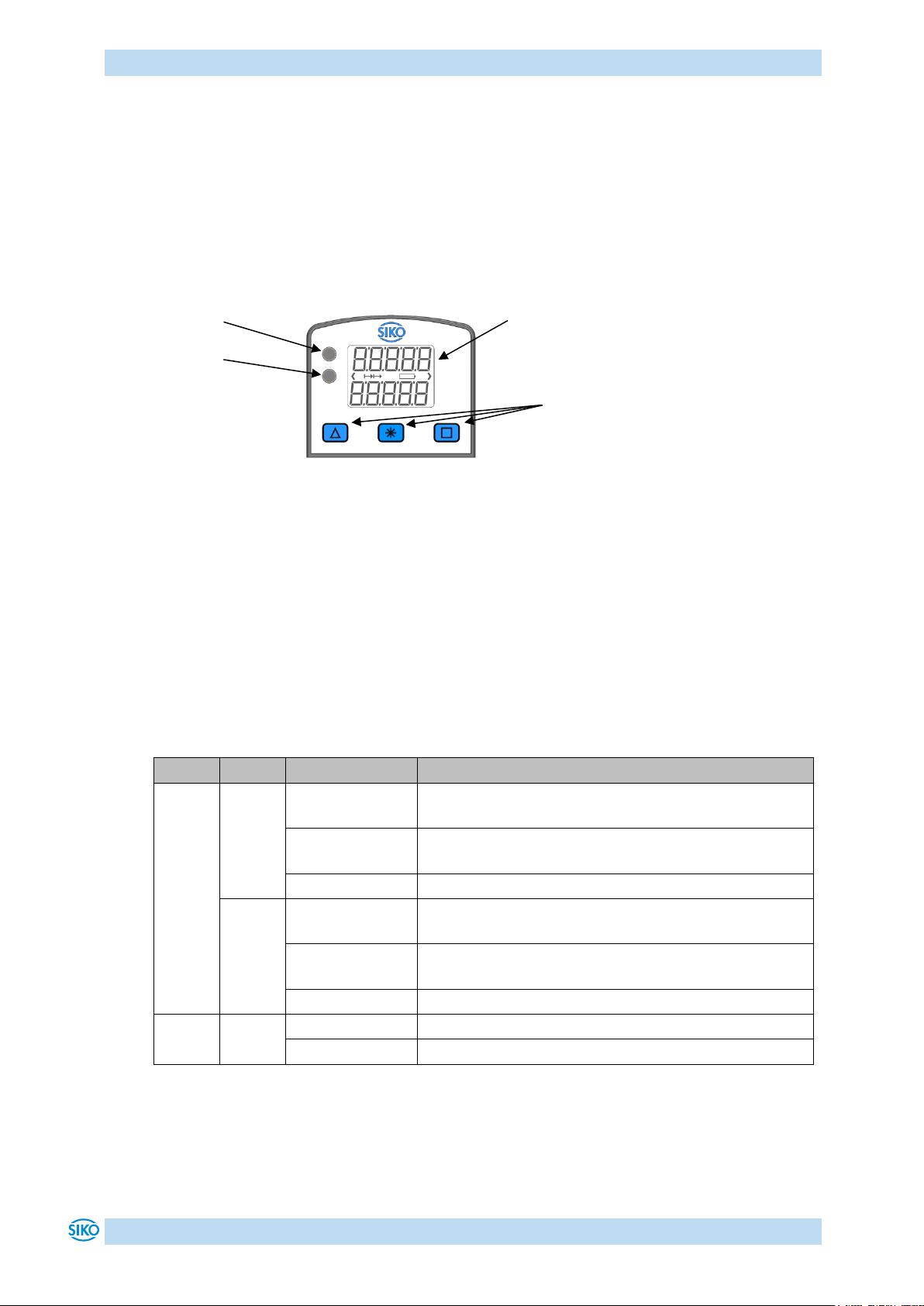
The actuator has a two-line display with special characters and three control keys. The keys
serve for actuator parameterization and control. Two LEDs (1, 2) inform about the actuator's
operating state.
Fig. 2: Control elements
3.2 LCD display
With supply voltage applied to the control, the actual value is displayed in the first line and
the set point value with factory settings in the second line.
The value displayed in the 2nd line can be adjusted via parameters.
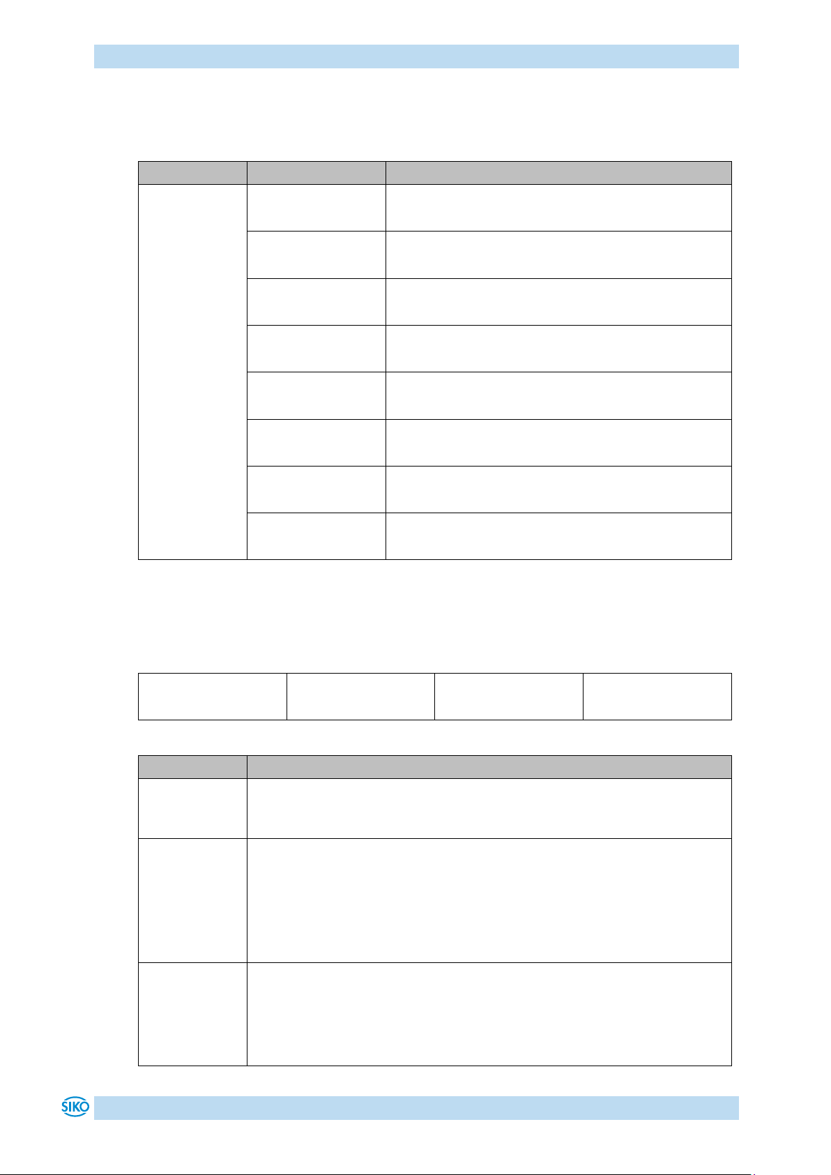
3.3 LED displays
LED
Colour
State
Description
LED1
green
on
Actuator is within the programmed position window.
Supply voltage of the output stage is applied.
blinking
Actuator is within the programmed position window.
Supply voltage of the output stage is missing.
off
Actuator is outside the programmed position window.
red
on
Actuator is outside the programmed position window.
Supply voltage of the output stage is applied.
blinking
Actuator is outside the programmed position window.
Supply voltage of the output stage is missing.
off
Actuator is within the programmed position window.
LED2
orange
on
Active bus operation
off
No bus operation
Table 1: LED displays
LED2
LED1
LCD display
Keys
Functional Description
AG05 Date: 15.06.2016 Art. No. 85677 Mod. status 139/16 Page 6 of 64
4Functional Description
4.1 Control of the drive
The drive can be controlled manually (stand-alone) and completely parameterized via the
keys. In bus operation you can disable drive control via the keys.
4.1.1 Value input
Enter values via the key and the key. Confirm entered values by pressing the key.
- Decimal place selection key
- Value input key
With value input via the keys, the display range is limited to -19999 …
99999. When entering values beyond this range via SIKONETZ5 or the
service protocol, "" will be displayed when you select the parameter.
4.1.2 Value selection
For some parameters you can select values from a list. Direct value input is not possible.
You can select a value from the list via the key. Confirm the value by pressing the key.
4.1.3 Operating modes
The following operating modes are distinguished: positioning mode and speed mode. In the
positioning mode there is the additional option of travelling in the inching mode.
4.1.3.1 Positioning mode
In the positioning mode, positioning to the specified set point is executed by means of a
ramp function (see Fig. 3), calculated on the basis of the actual position as well as the
programmed controller parameters P (proportional factor), I (integral factor), D (differential
factor), acceleration and speed.
Upon activation of the travel order, the actuator accelerates to the specified speed with the
acceleration programmed. The value of deceleration to the set point is defined by the
parameter 'a-Pos' as well.
If the actual position is within the programmed window, this will be signalled by LED1, in the
system status word and in the SIKONETZ5 status word. You can define the behaviour of the
actuator upon reaching the programmed window.
Changing controller parameters during a positioning process does not influence the current
positioning operation.

Functional Description
AG05 Date: 15.06.2016 Art. No. 85677 Mod. status 139/16 Page 7 of 64
Fig. 3: Ramp travel, direct positioning mode
4.1.3.1.1 Loop positioning
If the actuator is operated on a spindle or an additional gear, the spindle or external gear
backlash can be compensated by means of loop positioning. In this case, travelling to the
target value is always from the same direction. This direction of approach can be defined.
Example:
The direction from which every target position shall be driven to is positive.
Case 1 new position is greater than actual position:
Direct travel to the target position
Case 2 new position is smaller than actual position:
The actuator drives beyond the target position by the loop length; afterwards, the set
point is approached in positive direction.
Fig. 4: Positioning Loop+
Start position
Target position
Time
Speed
Speed
(Parameter no. 5)
Acceleration = deceleration
(Parameter no. 4)
Positioning: loop +
Set point
Positioning in positive
direction
Positioning in negative
direction
Loop length
-
+
Functional Description
AG05 Date: 15.06.2016 Art. No. 85677 Mod. status 139/16 Page 8 of 64
4.1.3.2 Inching operation
Inching operation is enabled in the 'positioning mode' only. You can program via parameters
acceleration as well as speed in the inching mode.
There is no compensation for spindle play (loop positioning) in this
operating mode.
4.1.3.2.1 Inching mode 1
The drive travels once from the current actual position by the position 'Delta Tipp' depending
on the mathematical sign of the value entered.
'Delta Tipp' <0: negative travel direction
'Delta Tipp' >0: positive travel direction
If the 'Spindle pitch' parameter is programmed to zero, then the travelling
way occurs by increments. If 'Spindle pitch' is unequal zero, then the
information of the 'Delta Tipp' parameter refers to the travel distance in
1/100 mm.
Reaching of the target position will be signalled accordingly.
The following conditions must be met for enabling the start of inching modes 1 and 2:
The actuator must not be switched to error
No active travel job
Supply voltage of the output stage is applied
If the actual position is outside the programmed limiting values, then
travelling from this position in the respective direction is possible by means
of inching mode 1 or 2!
4.1.3.2.2 Inching mode2
The actuator travels from the current position as long as the relevant command is active. You
can influence the inching speed via two parameters and it will be calculated in the actuator
as illustrated in the example below:
v - Tipp (Parameter no. 9) = 10 rpm (can only be changed in the idle state)
Offset inching 2 (Parameter no. 30) = 85 % (can be changed during inching operation)
The resulting inching speed in this example will be:
Inching speed = v - Tipp * Offset inching 2 = 10 rpm * 85 % = 9 rpm
The results are always rounded to integers. The minimum speed is 1 rpm.

Functional Description
AG05 Date: 15.06.2016 Art. No. 85677 Mod. status 139/16 Page 9 of 64
4.1.3.3 Rotational speed mode
With the set point enabled, the actuator when in the rotational speed mode accelerates to the
target speed and maintains this speed until the set point is disabled or a different target
speed specified.
The speed is adjusted immediately to the new value when the rotational target speed is
changed.
The arithmetical sign of the set point determines the travel direction in the rotational speed
mode.
Fig. 5: Ramp rotational speed mode
The following conditions must be met for enabling the start of the rotational speed mode:
The actuator must not be switched to error
No active travel job
Supply voltage of the output stage is applied
Limits 1 + 2 are inactivated in this operational mode.
4.1.4 Current limiting
The actuator is equipped with adjustable current limiting, which serves primarily for
protecting the actuator against overload.
With the default value set, the nominal speed indicated on the data sheet is achieved.
Actuator overload results in limiting the motor current to the set value.
As a consequence, the actuator cannot maintain the speed set, the contouring error increases.
With the contouring error exceeding the contouring error limit the actuator will enter the
state of error: contouring error.
The actual motor current cannot be stated by measuring the supply current.
With cycled output stages, the supply current does not correspond to the
motor current. The actual motor current can be read out via the interface or
indicated on the display.
Speed
Time
Target speed
(set point)
Acceleration
Parameter no. 8
'Stop'
Set point enabled
Disable set point
or set point = 0
Disable operation

Functional Description
AG05 Date: 15.06.2016 Art. No. 85677 Mod. status 139/16 Page 10 of 64
4.2 Manual control (stand-alone operation)
4.2.1 Start inching mode 2
After applying supply voltage, the actuator will be on the uppermost level of the menu
structure (default/delivery state). Positioning mode is active.
Pressing the key starts left-hand motion (inching operation 2).
Pressing the key starts right-hand motion (inching operation 2).
Releasing the respective key stops travel movement.
Pressing the key starts the parameterization/programming mode.
4.2.2 Specifying the set point and starting the travel order
4.2.2.1 Example: Starting positioning order to position 500
Preconditions:
The display is at the uppermost level of the menu structure (basic state).
Operating mode: Positioning mode
Key functions: enabled
Initial state: normal display
First press the key, then the key and hold down together.
The key enable time is counted down.
After expiry of the key enable time, the input field is released.
The first decimal place is active.
Press the key twice to change the active decimal place.
The third decimal place is active.
Press the key 5 times.
Value 500 will be displayed.
Confirm by pressing the key to start positioning.
4.2.2.2 Example: Starting positioning order to position -500
Preconditions:
The display is at the uppermost level of the menu structure (basic state).
Operating mode: Positioning mode
Key functions: enabled
For negative values to be entered, set first the value and only afterwards
the arithmetical sign. The value 0 cannot be entered.

Functional Description
AG05 Date: 15.06.2016 Art. No. 85677 Mod. status 139/16 Page 11 of 64
Initial state: normal display
First press the key, then the key and hold down together.
The key enable time is counted down.
After expiry of the key enable time, the input field is released
The first decimal place is active and blinks.
Press the key twice to change the active decimal place.
The third decimal place is active and blinks.
Press the key 5 times for entering the value.
Value 500 will be displayed.
Press the key twice to change the active decimal place.
The fifth decimal place is active and blinks.
Press the key 11 times for setting the arithmetical sign.
Value -500 will be displayed.
Confirm by pressing the key to start positioning.
Functional Description
AG05 Date: 15.06.2016 Art. No. 85677 Mod. status 139/16 Page 12 of 64
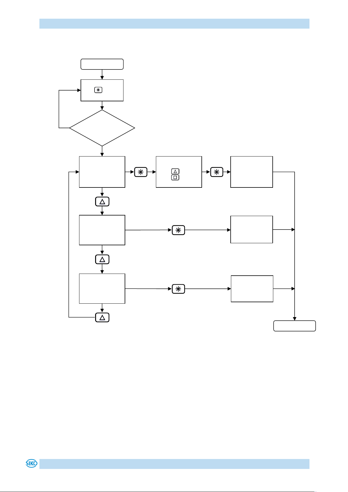
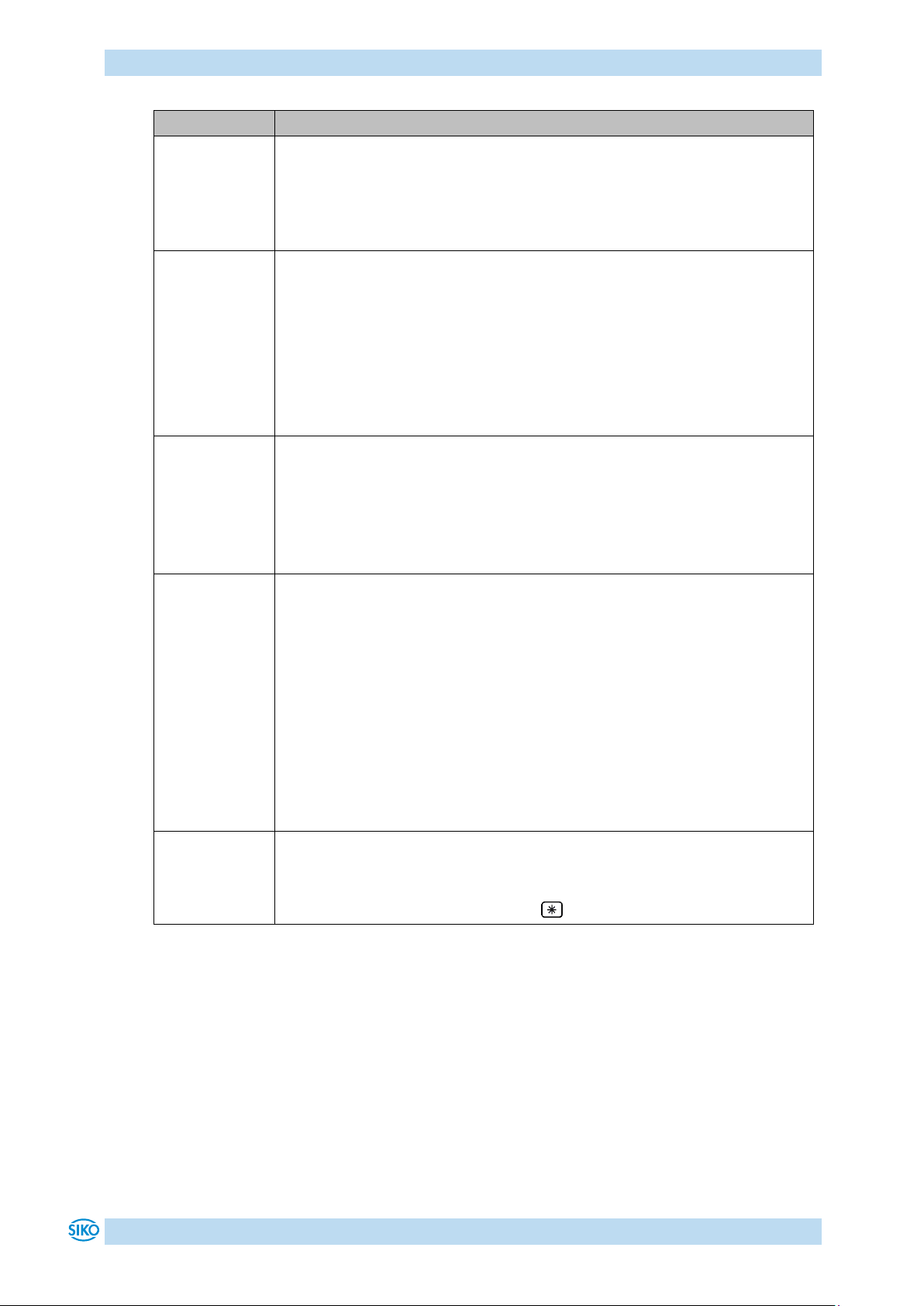
4.3 Menu selection
Fig. 6: Menu selection
Start
Hold down the
key
Changeable
parameters
Only readable
parameters
Error memory
PIN –input
required
key
key
see menu
only readable
parameters
see menu
error memory
Key enable
time
expired?
see menu
changeable
parameters
End
yes
no
Functional Description
AG05 Date: 15.06.2016 Art. No. 85677 Mod. status 139/16 Page 13 of 64
4.3.1 Changeable parameters
The Changeable parameters menu is subdivided into further sub-menus:
Menu
Sub-menu
Description
Bus parameters
Positioning
Actuator
Limiting values
Visualization
Options
Controller parameter
Exit menu
Table 2: Changeable parameters menu overview
4.3.1.1 Bus parameters
Menu
Sub-menu
Parameter
Description
Node address
Value range: 0 - 31
(see chapter 8: Parameter description Parameter no. 22)
Baud rate
Selection:
: 57600 baud
: 115200 baud
: 19200 baud
(see chapter 8: Parameter description Parameter no. 33)
Protocol
Selection:
: SIKONETZ5
: Service protocol
(see chapter 8: Parameter description Parameter no. 34)

Functional Description
AG05 Date: 15.06.2016 Art. No. 85677 Mod. status 139/16 Page 14 of 64
Parameter
Description
Bus Timeout
Value range: 0 –20
(see chapter 8: Parameter description Parameter no. 35)
Table 3: Bus parameter menu
4.3.1.2 Positioning
Menu
Sub-menu
Parameter
Description
Pos window
Value range: 0 - 1000
(see chapter 8: Parameter description Parameter no. 10)
Spindle pitch
Value range: 0 - 99999
(see chapter 8: Parameter description Parameter no. 13)
Display divisor
Selection:
: 1
: 10
: 100
: 1000
(see chapter 8: Parameter description Parameter no. 43)
Calibration value
Value range: -19999 … 99999
(see chapter 8: Parameter description Parameter no. 14)
Selection:
: no calibration
: Execute calibration
Offset
Value range: -19999 … 99999
(see chapter 8: Parameter description Parameter no. 32)
Sense of rotation
Selection:
: i sense of rotation (cw)
: e sense of rotation (ccw)
(see chapter 8: Parameter description Parameter no. 18)

Functional Description
AG05 Date: 15.06.2016 Art. No. 85677 Mod. status 139/16 Page 15 of 64
Parameter
Description
Pos Type
Selection:
: direct
: loop+
: loop–
(see chapter 8: Parameter description Parameter no. 19)
Loop length
Value range: 0 –30000
(see chapter 8: Parameter description Parameter no. 27)
Table 4: Positioning menu
4.3.1.3 Actuator
Menu
Sub-menu
Parameter
Description
Acceleration in the positioning mode
Value range: 1 –100
(see chapter 8: Parameter description Parameter no. 4)
Maximum speed in the positioning mode
Gear 66:1 value range: 1 - 75
Gear 98:1 value range: 1 - 50
(see chapter 8: Parameter description Parameter no. 5)
Acceleration in rotational speed mode
Value range: 1 - 100
(see chapter 8: Parameter description Parameter no. 6)
Acceleration in inching mode 1/2
Value range: 1 - 100
(see chapter 8: Parameter description Parameter no. 8)
Maximum speed in inching mode 1/2
Gear 66:1 value range: 1 - 75
Gear 98:1 value range: 1 - 50
(see chapter 8: Parameter description Parameter no. 9)
Numerator gear ratio
Value range: 1 - 10000
(see chapter 8: Parameter description Parameter no. 11)
Denominator gear ratio
Value range: 1 - 10000
(see chapter 8: Parameter description Parameter no. 12)
Table 5: Actuator menu

Functional Description
AG05 Date: 15.06.2016 Art. No. 85677 Mod. status 139/16 Page 16 of 64
4.3.1.4 Limiting values
Menu
Sub-menu
Parameter
Description
Limit 1
Value range: -19999 … 99999
(see chapter 8: Parameter description Parameter no. 15)
Limit 2
Value range: -19999 … 99999
(see chapter 8: Parameter description Parameter no. 16)
Current limiting
Value range: 25 - 110
(see chapter 8: Parameter description Parameter no. 29)
Contouring error limit
Value range: 1 - 30000
(see chapter 8: Parameter description Parameter no. 28)
Table 6: Limiting values menu
4.3.1.5 Visualization
Menu
Sub-menu
Parameter
Description
Display orientation
Selection:
: 0°
: 180°
(see chapter 8: Parameter description Parameter no. 45)
LED 2 orange function
Selection:
: Bus operation display
: Off
(see chapter 8: Parameter description Parameter no. 39)
Red LED 1 function
Selection:
: Indication of the operating status
: Off
(see chapter 8: Parameter description Parameter no. 40)
Functional Description
AG05 Date: 15.06.2016 Art. No. 85677 Mod. status 139/16 Page 17 of 64
Parameter
Description
Green LED 1 function
Selection:
: Indication of the operating status
: Off
(see chapter 8: Parameter description Parameter no. 41)
Decimal places
Selection:
: 0
: 0.0
: 0.00
: 0.000
: 0.0000
(see chapter 8: Parameter description Parameter no. 42)
Direction indication function
Selection:
: On
: inverted
: Off
(see chapter 8: Parameter description Parameter no. 44)
Displayed value of 2nd display line
Selection:
: Set point
: Output stage temperature
: Control voltage
: Output stage voltage
: Battery voltage
: Motor current
: Actual position
: Actual rotational speed
(see chapter 8: Parameter description Parameter no. 49)
Display test
Selection:
: no display test
: Start display test, pressing the key stops display test.
Table 7: Visualization menu

Functional Description
AG05 Date: 15.06.2016 Art. No. 85677 Mod. status 139/16 Page 18 of 64
4.3.1.6 Options
Menu
Sub-menu
Parameter
Description
Key enable time
Value range: 1 - 60
(see chapter 8: Parameter description Parameter no. 37)
Key function enable
Selection:
: Enable all key functions
: All key functions disabled
(see chapter 8: Parameter description Parameter no. 38)
Operating mode
Selection:
: Positioning mode
: Rotational speed mode
(see chapter 8: Parameter description Parameter no. 20)
Delta Inch
Value range: -19999 … 99999
(see chapter 8: Parameter description Parameter no. 17)
Inpos mode
Selection:
: Position control to set point
: Position control Off and short circuit of all motor windings
: Position control Off and drive enable
(see chapter 8: Parameter description Parameter no. 26)
Inching mode 2 acceleration type
Selection:
: static acceleration
: incremental acceleration
(see chapter 8: Parameter description Parameter no. 31)
Stop mode inching 2
Selection:
: stop with maximum deceleration
: stop with programmed deceleration
(see chapter 8: Parameter description Parameter no. 25)
Inching 2 Offset
Value range: 10 - 100
(see chapter 8: Parameter description Parameter no. 30)
PIN change
Value range: 0 - 99999
(see chapter 8: Parameter description Parameter no. 48)

Functional Description
AG05 Date: 15.06.2016 Art. No. 85677 Mod. status 139/16 Page 19 of 64
Parameter
Description
S commands
Selection:
: execute no S command
: execute no S command
: Set standard parameters to default
: Set controller parameters to default
: Set display parameters to default
: Set bus parameters to default
: Calibration
: Delete error memory
Table 8: Options menu
4.3.1.7 Controller parameters
Menu
Sub-menu
Parameter
Description
Controller parameter P
Value range: 1 - 500
(see chapter 8: Parameter description Parameter no. 1)
Controller parameter I
Value range: 0 - 500
(see chapter 8: Parameter description Parameter no. 2)
Controller parameter D
Value range: 0 - 500
(see chapter 8: Parameter description Parameter no. 3)
Table 9: Controller parameters menu
4.3.2 Readable parameters
Menu
Parameter
Description
Current output stage temperature
Current control voltage
Current output stage voltage
Current battery voltage

Functional Description
AG05 Date: 15.06.2016 Art. No. 85677 Mod. status 139/16 Page 20 of 64
Parameter
Description
Current motor current
Current actual position
Current actual speed
Gear reduction
Motor rated power
Encoder resolution
Display controller software version
Motor controller software version
Serial number
Production date
Table 10: Readable parameters menu
4.3.3 Error memory
Menu
Parameter
Description
Number of errors in the error memory
(see chapter 8: Parameter description Parameter no. 61)
xxxxx
Error 1
(see chapter 8: Parameter description Parameter no. 62)
xxxxx
Error 2
(see chapter 8: Parameter description Parameter no. 63)
xxxxx
Error 3
(see chapter 8: Parameter description Parameter no. 64)
xxxxx
Error 4
(see chapter 8: Parameter description Parameter no. 65)
xxxxx
Error 5
(see chapter 8: Parameter description Parameter no. 66)
xxxxx
Error 6
(see chapter 8: Parameter description Parameter no. 67)
xxxxx
Error 7
(see chapter 8: Parameter description Parameter no. 68)
xxxxx
Error 8
(see chapter 8: Parameter description Parameter no. 69)
xxxxx
Error 9
(see chapter 8: Parameter description Parameter no. 70)
Table of contents
Other Siko Recording Equipment manuals


Popular Recording Equipment manuals by other brands

Continental Electronics
Continental Electronics 212P-2 instruction manual

JBL
JBL Synthesis SDP-1 owner's manual

Vermona
Vermona fourMulator user guide

Marantz professional
Marantz professional PMD661MKIII user guide

Aiphone
Aiphone GH-VAX instructions

OSCILLATOR DEVICES
OSCILLATOR DEVICES GARBAGE COLLECTOR EXP user manual


