Sila EVI Series User manual

Split EVI DC Inverter Series
Installation Manual
AS 9,6 I-EVI AS 16,8 I-EVI, AS 18,8 I-EVI
Air to Water Heat Pump
Heating+Cooling+DHW
Refrigerant: R410A
PC board code:
LCD code:

Safety precaution
a. Toavoid electrical shock, make sure to disconnect power supply
1minute or more before operating the electrical part. Even after
1minute, always measure the voltage at the terminals of main circuit
capacitors or electrical parts and, before touching, make sure that
those voltages are lower than the safety voltage.
b. Power supply wire line size must be selected according to this
manual. And must be grounded.
c. Don’t put in hands or stick to air outlet grill when fan motor are
working.
d. Don’t use wet hand touch wire lines, and don’t pull any wire lines of the
unit.
e. Water or any other kind liquid is forbidden to poured into the unit.
f. Select correct air breaker and leakage protection switch.
g. Don’t touch the fin of source side heat exchanger, it may hurt your
finger.
h. If any wire line is loose or damaged, suggest let qualified person to fix it.

Important parts in heat pump
No.
Component
53
Fan
54
DC motor
35
Reservoir
28
Inverter compressor
55
Pressure gauge
31
Filter
46
Small shut-off valve
47
Large shut-off valve
23
Four-way valve
26
Main electronic expansion valve
27
Auxiliary electronic expansion valve
29
Plate heat exchanger economizer
16
Back repair board

Important parts in heat pump
No.
Component
60
Fan
61
DC motor
31
Plate heat exchanger economizer
28
Auxiliary electronic expansion valve
30
Main electronic expansion valve
53
Large shut-off valve
52
Small shut-off valve
23
Four-way valve
64
Pressure gauge
29
Filter
50
Reservoir
24
Gas-liquid separator
41
Inverter compressor
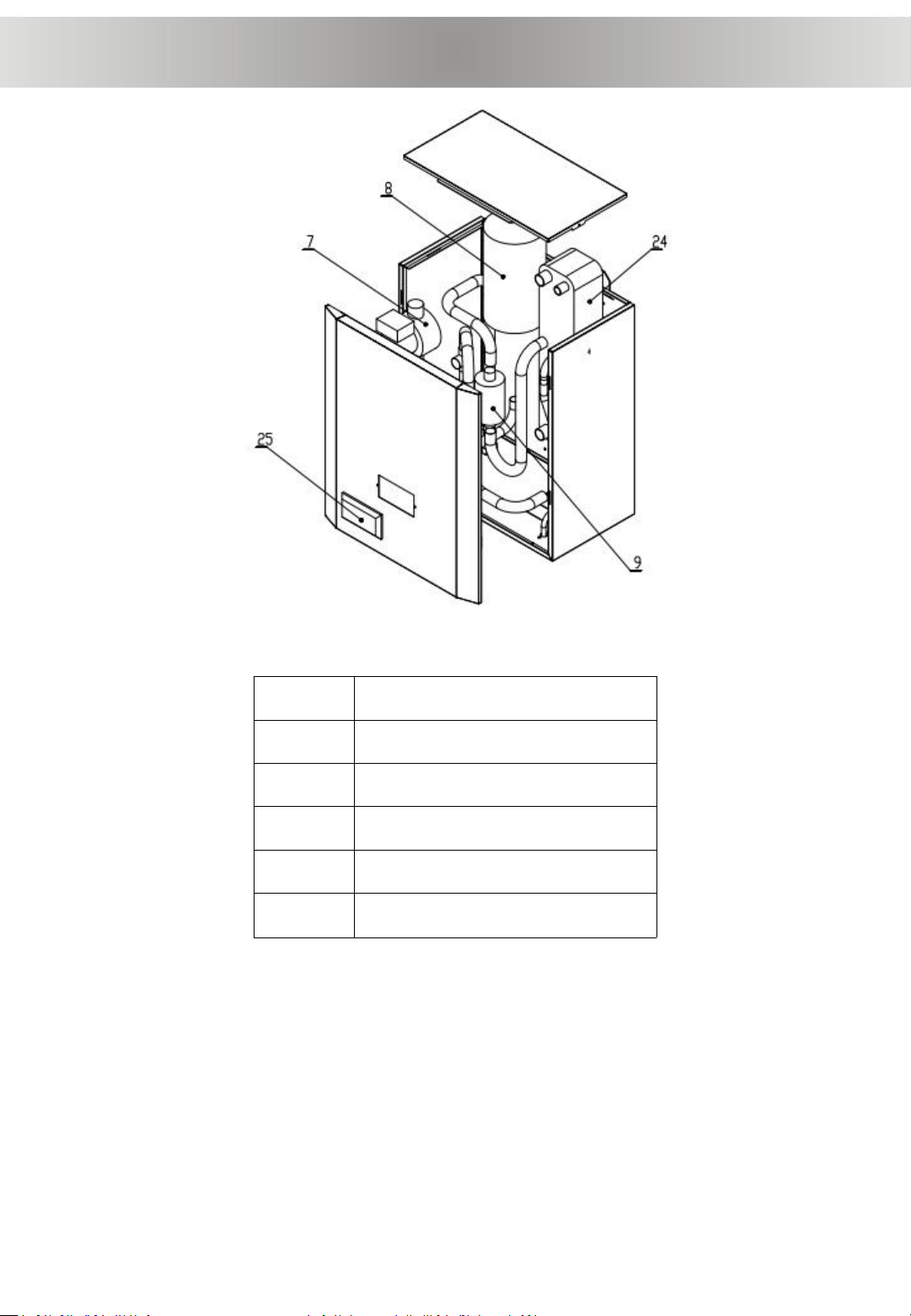
Important parts in heat pump
No.
Component
25
Controller
7
Inverter pump
8
Expension tank
24
Plate heat exchanger
9
Electric heater

Heat pump size
AS 9,6 I-EVI
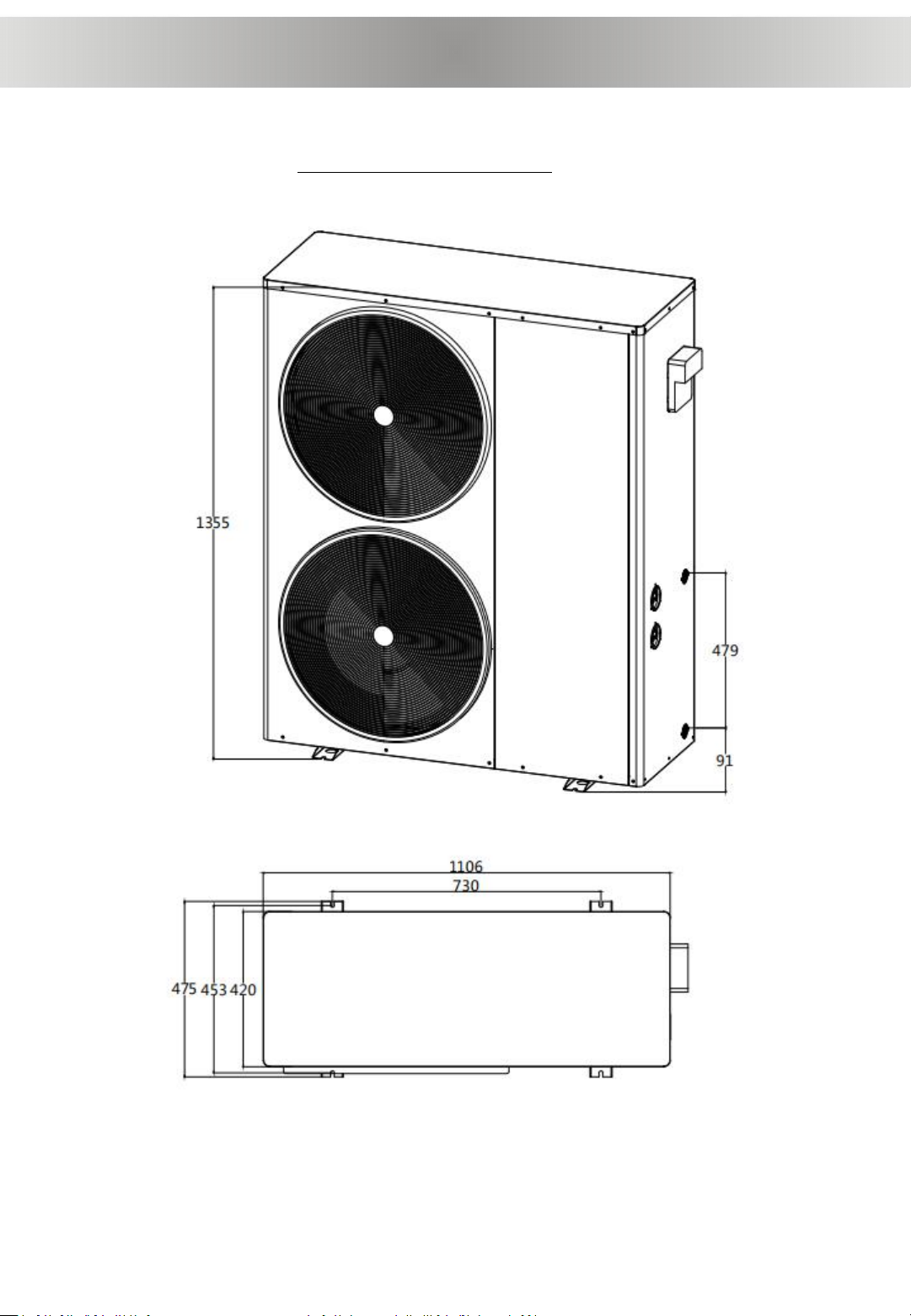
Heat pump size
AS 16,8 I-EVI, AS 18,8 I-EVI

Heat pump size
Indoor unit

Installation diagram
Primary circulation system

Installation diagram
Secondary circulation system

Distances to barrier and ground
1) The heat pump must be installed in open space. Normally is installedon the
roof of house.
2) The unit should be placed in dry and well-ventilated environment. If the
environment is humid, electronic components may get corroded orshort
circuit.
3) Heat pump mustn’t be installed in the environment wherecorrosive,
volatile, or flammable liquid or gas exists.
4) Because of the noise is a little loud, please don’t install the heatpump near
bedroom or living room or meeting room.
5) Please install a shed for the heat pump, otherwise, rain water can reduce the
lifetime of the shell, and snow may cover the air outlet.
6) Water drainage ditch should be set around the heat pump, whenheat
pump is working, there is condensing water flow down, or when defrosting,
there are plenty of water flow down too.
7) Heat pump should far away from kitchen exhaust, because thefinned tube
is not easy to clean if there is oil on it.
8) Heat pump must be installed on flat concrete blocks or a raised concrete
platform, or steel bracket. The bottom of the heat pump should be at least
50cm higher than ground, because rain water, snow may enter inside if the
installation is on ground.
9) Between heat pump and basic or bracket, at leas 4pcs anti-shock pads
should be placed.
10) Before make basic or bracket, please check heat pump dimension.
11) Before fix heat pump on basic, please confirm heat pump direction
according to project design.
12) Normally use expansion bolt to fix heat pump on concrete basic.
13) Make sure circulating water pipe must be ≥DN25 (or PPR32), and pipes
must be insulated.
14) When install water temp sensor on pipe or in water tank, make sure temp
sensor will not touch water directly, best through a sensor tube. Like below
picture.
≥0.5
m
Basic of installation

1. Installation site
1.1 The outdoor unit should be installed in a sunny and ventilated place to prevent the formation
of a cold field due to poor ventilation or in a dark place, which affects the use of the unit;
1.2 The outdoor unit should not be installed in a place with too much dust to prevent the dust
from adhering to the fin heat exchanger and affecting the heat exchange effect;
1.3 The outdoor unit should not be installed in places with corrosive gas to prevent the unit heat
exchanger from being corroded and affecting the service life;
1.4 The outdoor unit should be equipped with anti-vibration pads and fixed firmly with expansion
screws to prevent vibration, noise and displacement;
1.5 The outdoor unit should be installed in a place where it can be drained to prevent
condensation and ice formation;
1.6 The outdoor unit should be placed according to the installation distance diagram, and there
should be a bracket to prevent the short drainage distance from causing ice formation;
1.7 The indoor unit must be well-supported, installed on a wall, and the wall must be able to bear
the weight;
1.8 The indoor unit should not be installed outdoors in direct sunlight or rain.
2. Installation considerations
2.1 The copper pipe connecting the internal and external machines is 5 meters, and it cannot be
lengthened without permission. If you need to lengthen, you need to contact the manufacturer;
2.2 When the connecting copper pipe is bent, do not crush the copper pipe, otherwise it will
affect the normal operation of the unit;
2.3 After installation, use soapy water to detect leaks.
Installation details

Installation details
3. Outdoor unit installation
3.1 Outdoor unit installation distance requirements

3.2 The outdoor unit installation needs to be fixed on the bottom frame with expansion screws,
and the bottom corner of the main unit needs to be installed with a cushion
Anti-shock pad
Concrete basic
Expansion bolt
4. Indoor unit installation:
4.1 Indoor unit installation requires three expansion screws to fix the internal unit to the wall.
Installation details

5. Fix the connecting pipe
5.1 After the outdoor door unit and indoor unit are fixed, look for the nearest connection route,
punch a hole of 50-100mm at the location of the wall, pay attention to waterproof when drilling
5.2 Pass the two connecting pipes through the wall, and place the two ends at the connection
between the indoor and outdoor units
6. Fluorine copper tube connection
6.1 Indoor unit and connection location
Outdoor unit gas connector
Pipes connection

Indoor unit gas connector
6.2 Fluorine connection pipe specification:
CGK030V2LS connection pipe specification φ15.88 / φ12.7
CGK050V2LS connecting pipe specification φ19 / φ12.7
CGK060V2LS connecting pipe specification φ19 / φ12.7
7. Fluorine system pipeline connection steps
7.1 Remove the plastic cover of the globe valve, directly align the bell mouth of the connecting pipe
with the connection port on the heat pump, and then tighten the nut, paying attention to alignment,
otherwise it will cause air leakage
Remove cover Bell mouth
Pipes connection

7.2 After connecting the connecting pipes of the indoor and outdoor units, use a vacuum
pump to evacuate the air in the pipeline and the indoor unit to ensure the evacuation time
and ensure that the air in the pipeline is cleaned.
7.3 After evacuation, close the refrigerant meter valve, use a φ5 hex nut to open the shut-
off valve switch, close the shut-off valve switch after a little refrigerant enters the
connection pipe, then unscrew the connection pipe for evacuation, and then reopen all the
shut-off valve switches, Complete the connection.
Tool
Remove cover Switch
8. Leak detection
Fill an empty bottle with the right amount of detergent solution and water, shake it, and pour it into
all the connection ports to check whether there are bubbles emerging. If there are bubbles, it can
be judged that the refrigerant is leaking. It needs to be tightened immediately until no bubbles
come out.
9. Water system pipeline connection
9.1 Use pipe connections with specifications greater than or equal to DN25, and the connection
should be tightened to prevent water leakage;
9.2 If used for three functions of floor heating, cooling and hot water, a three-way valve needs to be
installed;
9.3 Automatic exhaust valve shall be installed at the highest part of the water system and the top of
the water tank.
Pipes connection

Wire line
10. Line connection
10.1 When connecting the main power supply, please note that the wire diameter of the power cord
must be greater than or equal to the recommended wire diameter, and must be reliably
grounded.
10.2 The connection terminal of the water pump can be used as the power supply of the water
pump. The water pump with the PWM signal needs to be connected to the signal line. Pay
attention to distinguish the power line and the signal line of the pump, which can be
distinguished according to the number of the connection line
10.3 Models with inside electric heater can be directly wired according to the mark.
10.4 Models with external electric heater need to select a suitable wire diameter according to the
electric heating power. The electric heating terminal cannot be used directly as an electric
heating power supply, but only as a control line. The main power supply needs to be equipped
with an AC contactor according to the power size
10.5 The connection of the three-way valve is 2 live wire and 1 neutral wire, and the switching
direction of the three-way valve must be accurately judged when wiring, otherwise it will
damage the unit and render it unusable
10.6 The user hot water probe using the three functions of floor heating, cooling and hot water
needs to be installed in the hot water tank.
10.7 Corresponding numbers of the inlet and outlet probe lines and the water flow switch
connection line can be directly connected
11. Power wire diameter selection
Voltage: 220V~240V/50Hz or 60 Hz/1Ph Electric heater: 3KW
N
L

12. Wiring terminal diagram with self water pump and electric heater
AS 9.6 I-EVI AS 16.8 I-EVI AS 18.8 I-EVI
Line(mm)
6
10
10
Max.
Current(A)
15
26
30
Terminal

13.Wiring terminal diagram of externally electric heater and water pump
Terminal
This manual suits for next models
3
Table of contents
Popular Water Pump manuals by other brands

Blumfeldt
Blumfeldt 10031255 manual

FLOWTECH
FLOWTECH flowpac compact SE Operation and maintenance manual

Pentair Pool Products
Pentair Pool Products Delta D2CX20-21 Installation & Service Manual with Parts List

Hayward
Hayward VS Omni How-to guide

Tsurumi Pump
Tsurumi Pump C series Operation manual

All Pond Solutions
All Pond Solutions ACP-500 instruction manual


Little Giant
Little Giant HRK-360S instruction sheet

Aqua Medic
Aqua Medic EcoDrift 4.1 Operation manual

Little Giant
Little Giant 1-EAYS Installation instructions manual

red lion
red lion RL-SWJ Series owner's manual

Little Giant
Little Giant VCCA-20-P owner's manual

Little Giant
Little Giant 1-EA Series quick start guide