Silca SBB User manual

®
D432985XA
vers.
3.0
Operating manual

© 2006 SILCA S.p.A - Vittorio Veneto
This manual has been drawn up by SILCA S.p.A.
All rights reserved. No part of this publication may be reproduced or used in any form or by any means (photocopying,
microfilm or other) without the written permission of SILCA S.p.A.
Published
: March 2007
Printed
in Vittorio Veneto
by SILCA S.p.A.
via Podgora, 20 (Z.I.)
31029 VITTORIO VENETO (TV) – Italy
IMPORTANT NOTE: in compliance with current regulations relating to industrial property, we hereby state that the
trade-marks or trade names mentioned in our documentation are the exclusive property of authorized
manufacturers of locks and users.
Said trade-marks or trade names are nominated only for the purposes of information so that any lock for which our
keys are made can be rapidly identified.

INDEX
1 MACHINE DESCRIPTION ........................................................................................................ 2
1.1 MAIN CHARACTERISTICS ................................................................................................... 2
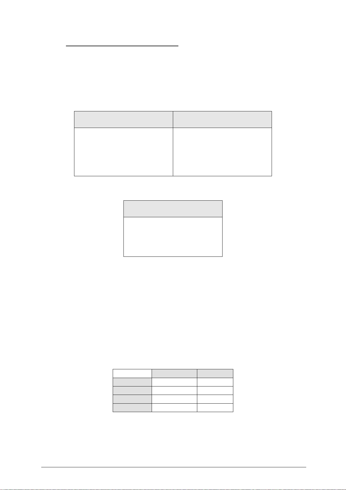
1.2 TECHNICAL DATA ................................................................................................................ 3
1.3 WORKING PARTS ................................................................................................................. 4
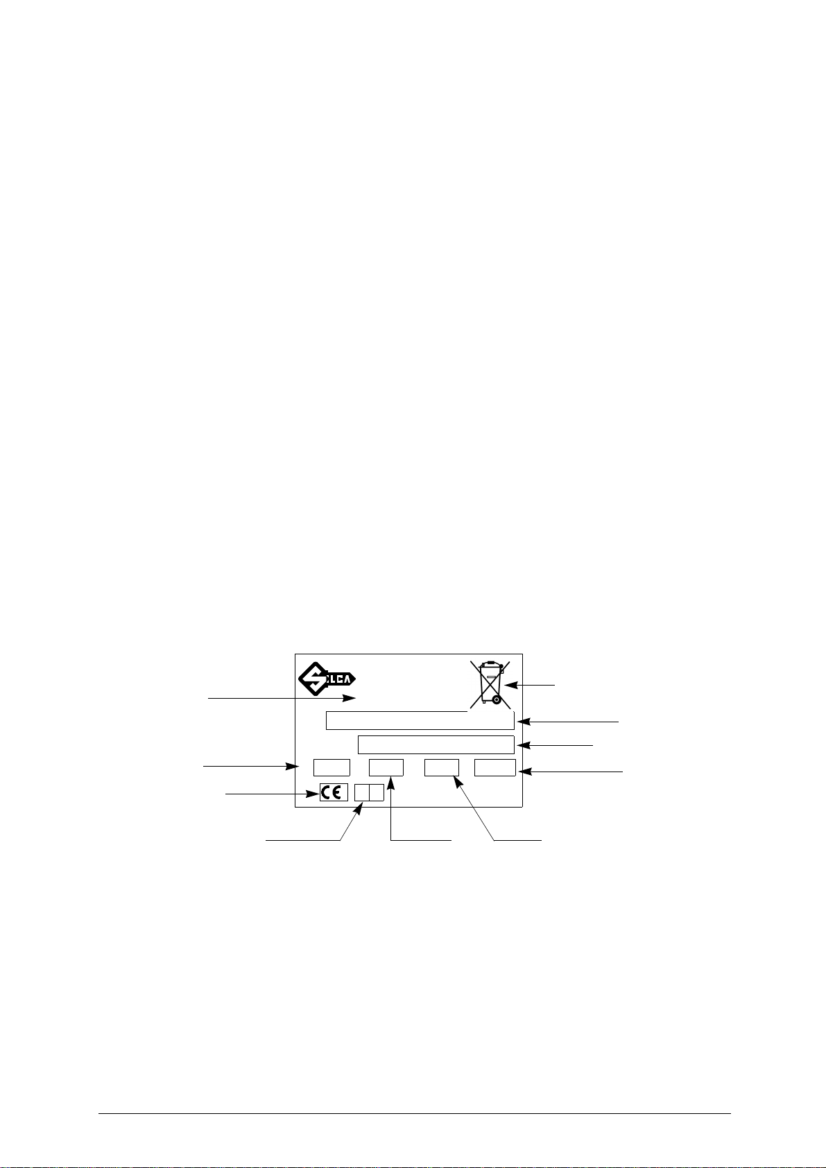
1.4 SYMBOLS ............................................................................................................................. 5
2 TRANSPORT ............................................................................................................................6
2.1 PACKING ............................................................................................................................... 6
2.2 UNPACKING ......................................................................................................................... 6
2.3 HANDLING ............................................................................................................................ 6
3 ACCESSORIES PROVIDED .....................................................................................................7
4 INSTALLATION AND PREPARATION ....................................................................................7
4.1 PREPARATION FOR USE - INITIAL OPERATIONS ............................................................ 7
4.2 CHECKING FOR DAMAGE ...................................................................................................7
4.3 ENVIRONMENTAL CONDITIONS ........................................................................................ 7
4.4 SOFTWARE UPDATING ....................................................................................................... 7
5 REGULATION AND GAUGING ................................................................................................7
6 USING THE MACHINE .............................................................................................................8
6.1 START-UP ............................................................................................................................. 8
6.2 PASSWORD .......................................................................................................................... 8
6.2.1 PASSWORD (MEMORIZED) ................................................................................................... 9
6.3 MAIN MENU .......................................................................................................................... 9
6.4 IMMOBILIZER MENU / REMOTE CONTROLS .................................................................... 9
6.4.1 SELECTING THE CAR MAKE ...............................................................................................10
6.4.2 CAR MODEL NOT ENABLE ..................................................................................................10
6.4.3 CAR MODEL ENABLED ........................................................................................................10
6.4.4 COMMUNICATION PROCEDURE WITH THE IMMOBILIZER ..............................................11
6.5 PIN CODE SERVICE ...........................................................................................................11
6.5.1 VAG PIN CODE ...................................................................................................................... 11
6.5.1.1 DISABLED VEHICLE MODEL .................................................................................................11
6.5.1.2 ENABLED VEHICLE MODEL ..................................................................................................11
6.5.1.3 COMMUNICATION PROCEDURE FOR PIN CODE READING .............................................12
6.5.2 VAG 7-4 PIN CONV. .............................................................................................................. 12
6.5.2.1 PIN 7 ........................................................................................................................................12
6.5.2.2 DEALER ..................................................................................................................................13
6.5.2.3 IMPORTER ..............................................................................................................................13
6.5.2.4 PIN 4 ........................................................................................................................................13
6.5.3 HYUNDAI
®
/ KIA
®
PIN CODE................................................................................................. 14
6.6 SETUP ................................................................................................................................. 15
6.6.1 ENABLING ............................................................................................................................. 15
6.6.2 LANGUAGE ...........................................................................................................................18
6.6.3 SERIAL NUMBER .................................................................................................................. 18
6.6.4 CLOCK ................................................................................................................................... 18
6.6.5 VERSION ............................................................................................................................... 18
6.6.6 MEMORIZE PASSWORD ......................................................................................................19
6.6.7 KEYS REFERENCES ............................................................................................................19
6.7 ARCHIVE ............................................................................................................................. 19
6.7.1 SEARCH ................................................................................................................................ 19
6.7.2 PRINTOUT ............................................................................................................................. 20
6.7.3 ARCHIVE ERASE .................................................................................................................. 21
6.8 TEST .................................................................................................................................... 21
6.8.1 KEYBOARD ...........................................................................................................................21
6.8.2 TEXT ...................................................................................................................................... 21
6.8.3 GRAPHICS ............................................................................................................................. 21
6.8.4 UPDATE SWITCH CAN .........................................................................................................22
7 MODEL CHANGE....................................................................................................................23
8 WARNING/ERROR MESSAGES ............................................................................................24
9 HELP MENU ............................................................................................................................31
10 MAINTENANCE ......................................................................................................................33
10.1 CHECKING WIRING ...........................................................................................................33
11 WASTE DISPOSAL ................................................................................................................34
12 ASSISTANCE ..........................................................................................................................35
12.1 HOW TO REQUEST SERVICE ........................................................................................... 35


Copyright Silca 2006 1
Operating Manual - English SBB
GENERAL
The device is designed to the principles of European CE Directives.
The materials used in its manufacture are not dangerous and their use complies with directives. Its design
features make the machine and all its components completely safe to use.
FURTHER RISKS
There are no further risks arising from the use of the machine
.
PROTECTION AND SAFETY PRECAUTIONS FOR THE OPERATOR
The operations for which the machine has been designed are easily carried out at no risk to the operator
.
SAFETY REGULATIONS
To operate under conditions of maximum safety do not use the device without reading and understanding
clearly the contents of this operating manual.
• Check the electrical wiring periodically; if the wires are worn they should be repaired or replaced.
• Never work with wet, greasy or oily hands.
• Disconnect the device from the mains when it is not in use or in order to carry out maintenance work.
• Never tug at the power supply wire; make sure it does not come into contact with oil, sharp edges or heat.
• It is dangerous to use the device in areas at risk (damp or wet).
• Always work in a well lighted area.
• Keep the work area clean and remove all tools before turning on the machine.
• All visitors, children in particular, must keep at a safe distance and not touch the machine or electrical wiring.
•
Do not use the device for purposes different from those described in the Operating Manual.
POWER SUPPLY
The machine is supplied with electricity at 12 Vdc provided by the vehicle battery, or as an alternative can
be powered from a 15 Vdc universal feeder supplied with the machine
.
TURNS ON
The machine turns on automatically when the connection (OBD II or Optional) is connected to the diagnostics
socket or one of the feeder wires supplied with the machine is used.
IDENTIFICATION OF THE SBB DEVICE
The device has an identification plate showing its serial number
(fig. 1).
Fig. 1
(*) see chap. 11 "WASTE DISPOSAL", page 34.
N° MATRICOLA
SERIAL No.
TIPO
TYPE
VW
HZ A
manufacturer’s
address
serial No.
type of machine
working
frequency
absorbed current
power
year of
manufacture
CE mark
working
voltage
®
MADE IN ITALY
SILCA SPA
VIA PODGORA 20
TREVISO - ITALY
Tel. 0438-9136
Fax 04138-913800
e-mail info@silca.it
absorbed
L

2 Copyright Silca 2006
SBB Operating Manual - English
1MACHINE DESCRIPTION
The machine is used to easily programme keys with transponders in the centralized immobilizer units of a
number of car models. In particular, it can:
- memorize all the keys in the centralized immobilizer unit;
- erase keys already in the memory;
- read the immobilizer ID code – IMMO ID (if applicable);
- read the mechanical code for the key (if applicable);
- add one or more keys;
- read the number of keys in the memory (if applicable);
- read any errors/anomalies in the centralized immobilizer unit;
- erase/zero any errors found;
- provide help;
- Memorize the remote controls.
The machine is provided with a password to prevent unauthorized use. Users have at their disposal a
functions menu to meet all possible requirements during operation.
NOTE:
Once the machine is connected to the power mains it’s automatically switched on. To turn
it off exit from function and unplug the machine from the mains
.
1.1 MAIN CHARACTERISTICS
OPERATING METHODS
- Adds or deletes keys and remotecontrols from the immobilizer control unit by connecting SBB to the vehicle
diagnostics input.
SPECIAL FUNCTIONS
- Storage in the User Data Archive of all operations carried out;
- Multi-language program;
- Machine test;
-
Read the PIN CODE (where possible
);
- Help (operational help for: type and position of connectors, procedures, keys, types of transponders, etc...).
PASSWORD
A principle password is needed to enable SBB (required every time the program is turned on), issued by
the supplier/distributor by means of a special "USE AGREEMENT FORM
".
SBB - FULL LOADED CONFIGURATION
BASIC SOFTWARE
ACURA
®
,
ALFA ROMEO
®
, AUDI
®
, BUICK
®
, CADILLAC
®
, CHEVROLET
®
, CHRYSLER
®
, CHRYSLER
®
CAN,
CITROËN
®
, DODGE
®
, DODGE
®
CAN, EAGLE
®
, FIAT
®
, FIAT
®
-PSA, FORD
®
, FORD
®
AUSTRALIA, FORD
®
USA,
GENERAL MOTORS
®
BRAZIL, HOLDEN
®
, HONDA
®
, HONDA
®
USA, HYUNDAI
®
, JAGUAR
®
, JEEP
®
, JEEP
®
CAN,
KIA
®
, LANCIA
®
, LAND ROVER
®
, LEXUS
®
, LINCOLN
®
, MAZDA
®
, MERCURY
®
, MITSUBISHI
®
, MITSUBISHI
®
AUSTRALIA, MITSUBISHI
®
GREEK, MITSUBISHI
®
USA, NISSAN
®
, NISSAN
®
JAPAN, NISSAN
®
TRUCKS, NISSAN
®
USA, OLDSMOBILE
®
, OPEL
®
CAN BUS, PEUGEOT
®
, PONTIAC
®
, RENAULT
®
, RENAULT
®
CAN BUS, ROVER
®
,
SEAT
®
, SKODA
®
, SUBARU
®
, SUZUKI
®
, TOYOTA
®
, VOLKSWAGEN
®
, VOLKSWAGEN
®
BRAZIL, SPECIAL FUNCTION
ZZ-FNT 01, SPECIAL FUNCTION ZZ-FNT 02, SPECIAL FUNCTION ZZ-FNT 03, SPECIAL FUNCTION ZZ-FNT 04
.
-
These makes are all enabled for use
.
SOFTWARE UPDATE (NEW MAKES RELEASED
)
-
To use the new makes loaded with the SW update (after purchase) you may proceed in two different
ways
:
ENABLING BY PASSWORD ENABLING BY TOKEN
Enter a different password specific to
each new make released (see Ch.
“Enabling”) then you can always use the
device for that given make.
Apply for the passwords on the special
form "USE AGREEMENT SHEET“
included in the software update kit.
Use a credit that is reduced every time
key programming/deletion is carried out.
Credits can be purchased and loaded
onto SBB by means of a smart card (
see
chap. 6.6.1 "ENABLING"
).

Copyright Silca 2006 3
Operating Manual - English SBB
SBB - PAY PER USE CONFIGURATION
BASIC SOFTWARE
ACURA
®
,
ALFA ROMEO
®
, AUDI
®
, BUICK
®
, CADILLAC
®
, CHEVROLET
®
, CHRYSLER
®
, CHRYSLER
®
CAN,
CITROËN
®
, DODGE
®
, DODGE
®
CAN, EAGLE
®
, FIAT
®
, FIAT
®
-PSA, FORD
®
, FORD
®
AUSTRALIA, FORD
®
USA,
GENERAL MOTORS
®
BRAZIL, HOLDEN
®
, HONDA
®
, HONDA
®
USA, HYUNDAI
®
, JAGUAR
®
, JEEP
®
, JEEP
®
CAN,
KIA
®
, LANCIA
®
, LAND ROVER
®
, LEXUS
®
, LINCOLN
®
, MAZDA
®
, MERCURY
®
, MITSUBISHI
®
, MITSUBISHI
®
AUSTRALIA, MITSUBISHI
®
GREEK, MITSUBISHI
®
USA, NISSAN
®
, NISSAN
®
JAPAN, NISSAN
®
TRUCKS, NISSAN
®
USA, OLDSMOBILE
®
, OPEL
®
CAN BUS, PEUGEOT
®
, PONTIAC
®
, RENAULT
®
, RENAULT
®
CAN BUS, ROVER
®
,
SEAT
®
, SKODA
®
, SUBARU
®
, SUZUKI
®
, TOYOTA
®
, VOLKSWAGEN
®
, VOLKSWAGEN
®
BRAZIL, SPECIAL FUNCTION
ZZ-FNT 01, SPECIAL FUNCTION ZZ-FNT 02, SPECIAL FUNCTION ZZ-FNT 03, SPECIAL FUNCTION ZZ-FNT 04
.
- Two different methods are available for using the new makes:
SOFTWARE UPDATE (NEW MAKES RELEASED
)
To use the new makes downloaded with the SW update (after purchase) proceed only as follows
:
SOFTWARE UPDATE
The machine can be updated through an RS232 serial line connection with a personal computer.
POWER SUPPLY
-
From the car through an OBD II connector
;
-
From the car through the cigarette lighter plug
;
-
From the mains through a universal feeder and special cable
.
1.2 TECHNICAL DATA
POWER SUPPLY
-
8-45 Volt (typically 12Volt from the vehicle diagnostic inlet or cigarette lighter plug
).
-
Universal feeder
:
DIMENSIONS
Length: 220 mm
Width: 165 mm
Height: 50 mm
Weight: 300 g.
ENABLING BY
MODEL CHANGE
ENABLING BY TOKEN
By using an optional SMART CARD
“MODEL CHANGE” it is possible to
enable all the makes to use the basic
Software.
The card must be purchased and the
enablings have to be downloaded in
SBB by means of a SMART CARD (see
chap. 7 "MODEL CHANGE").
Use a credit that is reduced every time
key programming/deletion is carried out.
Credits can be purchased and loaded
onto SBB by means of a SMART CARD
(
see chap. 6.6.1 "ENABLING"
).
ENABLING BY TOKEN
Use a credit that is reduced every time
key programming/deletion is carried out.
Credits can be purchased and loaded
onto SBB by means of a smart card (
see
chapter “Enabling”
).
INPUT OUTPUT
Tension 90-264 Vac 15 Vdc
Current 1.0Arms @ 90V 1 A
Frequency 47-63 Hz
Power 15 W

4 Copyright Silca 2006
SBB Operating Manual - English
1.3 WORKING PARTS
Fig. 2
A - Retro illuminated LCD graphic display
B -
23-key keypad (numerical, functions, arrows, ESC, ENTER
)
C - Parallel Port (25 Poles) to communicate with the vehicle
D - Serial Port RS232 (9 Poles) use only for Serial cable
E - Socket for cigarette lighter power cable or feeder
F -
Standard OBD II cable
G -
Cigarette lighter power
cable
H - Feeder
J - Serial cable
B
A
C D E

Copyright Silca 2006 5
Operating Manual - English SBB
MAIN FEATURES
KEYPAD
The machine keypad allows the user to interact with it rapidly and easily. At any given time only the keys
involved in the cycle in progress are enabled
.
Fig. 3
LIQUID CRYSTAL DISPLAY
Retro illuminated LCD graphic display
(128x64 pixel or 21x8
characters
).
1.4 SYMBOLS
The box shows the machine screen and relative displays, as shown below
:
Methods for selecting a specific function:
- Use the arrow Left/Right keys,
the point where the cursor “>“shows the item required, then press
ENTER
;
-
Digit a number
(xx)
from the keypad to access the item required directly from the menu
.
Example:
to access the
GRAPHICS TEST
menu
(73)
either use the arrows to select first the
TEST
menu
(7)
, press
ENTER
, then the
GRAPHICS
menu
(3)
and press
ENTER
, or digit
(73)
which corresponds to the
GRAPHICS
TEST (73)
.
HELP function keys
Left-Right arrow keys,
move the cursor to the left or to the right
Up-Down arrow keys,
move the cursor up or down
(ENTER) key confirms data entered or selection made
(ESC) key quits or returns to the previous screen/status
- MAIN MENU -
1 - IMMOBILIZER
2 - REMOTE CONTROLS
> 3 - PIN CODE SERVICE
4 - SET UP
5 - DATA BASE
6 - TEST
- TEST -
1 - KEYBOARD
2 - TEXT
>3 - GRAPHICAL
4 - UPDATE SWICH CAN

6 Copyright Silca 2006
SBB Operating Manual - English
2 TRANSPORT
The machine and its components are easily transported by one person and its handling does not incur
any hazards
.
2.1 PACKING
The packing ensures safe transport for the machine and protects all its parts
.
To avoid knocks damaging the machine, we recommend using the original carrying case and packing
every time it is transported
.
Fig. 4
2.2 UNPACKING
To remove the machine from its packing
:
1)
take care not to damage the box when opening as it can be used again (transfers, dispatch to the
manufacturer for repairs or maintenance
).
2)
check the contents of the packing case, which comprise
:
-1
carrying case
;
-1
machine
;
-1
universal feeder
;
-1
centralized unit connecting cable (universal), OBDII – 00 connector
;
- 1 serial cable;
-1
power supply cable with cigarette lighter plug
;
-1
set of documents: user’s manual, guarantee form and user’s agreement
;
- 1 CD program
2.3 HANDLING
Always replace the machine in its carrying case after use
.

Copyright Silca 2006 7
Operating Manual - English SBB
3ACCESSORIES PROVIDED
The device comes complete with
:
-
universal feeder
;
-
centralized unit connection cable (OBD II-00 connector
);
-
serial cable
;
-
power supply cable with cigarette lighter plug
;
-
CD program (to be used in the event of loss of the program on the machine
).
4INSTALLATION AND PREPARATION
Installation can be carried out by the purchaser and does not require special skills. The machine is
supplied ready for use – however, some checks and preparation are necessary before use
.
4.1 PREPARATION FOR USE - INITIAL OPERATIONS
-
power the machine by means of the supply socket (E)
;
-
check that the serial number stamped on the device is the same as the one shown on the display; enter
the password (to enable use
) (see chap. 6.2 "PASSWORD", page 8);
-
select the language
;
4.2 CHECKING FOR DAMAGE
The device will not normally damage if transport, unpacking and installation have all been carried out
according to the instructions in this manual; however it is always advisable to check that the machine has not
suffered any damage.
Should faulty operation arise that is not connected with the above-mentioned conditions, please contact After-
Sales Service.
4.3 ENVIRONMENTAL CONDITIONS
To ensure that the best use is made of the machine and that the keys with transponders produced work
properly, it is important to bear in mind operating conditions and temperature.
Given the characteristics of the transponders on the keys, in order to memorize them, THE
TEMPERATURE MUST BE ABOVE 5° C.
Ideal working conditions for the machine are therefore
:
-
temperature: from 5° to 40° C
.
4.4 SOFTWARE UPDATING
The machine software can be updated by connection to a personal computer
.
ATTENTION:
the RS232 socket for connection to the PC is located on the front
,
near the display
.
Use the RS232 serial cable provided and follow the instructions for updating
.
5REGULATION AND GAUGING
The machine is designed not to require any gauging or regulation
.

8 Copyright Silca 2006
SBB Operating Manual - English
6 USING THE MACHINE
This chapter describes all the operations required to memorize, erase, or add keys to the centralized
immobilizer unit by connecting SBB to the vehicle diagnostics input
.
6.1 START-UP
When the machine is turned on the display shows the logo
:
After a few seconds the following message appears
:
The wording
“Update: XXXXXXX”
give the level of updating for the program and database.
The wording “
Ver (SW) XX.XX.XX
” indicates the software version.
The wording “
Ver (DB) XX.XX.XX
” indicates the make and model Database version on the machine.
The wording
“S.N.: XXXXXXXXXXXXX”
give the machine serial number.
Check that the serial number shown on the display is the same as that on the document "USER’S
AGREEMENT" and on the label attached to the back of the machine
.
Press
F1
to continue
.
6.2 PASSWORD
When selection has been made, the following message appears
:
To use the machine enter the password issued by the supplier/dealer, comprising
8 numerical characters
.
-
enter the password and press
ENTER
.
CORRECT PASSWORD
If the password is correct, the message below appears
:
After a few seconds the program enters the main menu.
S.N. : XXXXXXXXXXXXX
Ver. (SW): XXX.XX.XXX
Ver. (DB): XX.XX
Update : XXXXXXX
(F1) to continue
INSERT PASSWORD:
XXXXXXXX
RIGHT PASSWORD
®

Copyright Silca 2006 9
Operating Manual - English SBB
WRONG PASSWORD
If a wrong password has been entered, a beep advises the user and the display shows
:
-
Repeat the operation and press
ENTER
.
6.2.1 PASSWORD (MEMORIZED)
If the password has already been memorized on the machine (chap. 6.6.6 "MEMORIZE PASSWORD", page
19), when
F1
is selected the following message appears:
Wait a few seconds for the display to show the main menu
.
6.3 MAIN MENU
There are two ways to choose the menu
:
-
Use the
, arrow keys for selection then press
ENTER
, or
digit the number
corresponding to the
function.
6.4 IMMOBILIZER MENU / REMOTE CONTROLS
This function contains the database of vehicle
makes / models / years
for which the device is enabled and
can carry out the specific functions involved.
-Select
“IMMOBILIZER/REMOTE CONTROLS”
;
from the MAIN MENU to view a list of car makes on the
display
.
WRONG PASSWORD
INSERT PASSWORD:
XXXXXXXX
PASSWORD SAVED
- MAIN MENU -
1 - IMMOBILIZER
2 - REMOTE CONTROLS
> 3 - PIN CODE SERVICE
4 - SET UP
5 - DATA BASE
6 - TEST
- MENU IMMOBILIZER -
AUDI
SEAT
SKODA
>VOLKSWAGEN
OPEL
FORD

10 Copyright Silca 2006
SBB Operating Manual - English
SELECTING THE CAR MAKE
- Use the arrow keys to select
the make, then press
ENTER
.
- Press
ESC
to quit.
After selecting the make the display will show the list of car models
.
FUNCTION F1
Press the
“F1”
key to show informationrelating to the
make/model
selected (type and position of connectors,
procedures, keys, types of transponder, etc.) (see chap. 9 "HELP MENU", page 31).
6.4.1 SELECTING THE CAR MAKE
SBB is not always able to automatically recognize all the immobilizer central units and is therefore unable to
automatically choose the communication procedure to launch. It is therefore
NECESSARY
to select the right
MAKE MODEL
ANY OTHER CHARACTERISTICS
(Petrol, Diesel,
red key system
, etc.)
to which
the specific communication procedure is associated
.
For more information about the car model see the Functions Menu of the specific make.
6.4.2 CAR MODEL NOT ENABLE
If a car model that is not enabled is selected, a beep is heard and the display shows
:
6.4.3 CAR MODEL ENABLED
If a car model that is enabled has been selected, the display shows
:
- Press
ESC
to quit.
- Press
ENTER
to continue.
- VOLKSWAGEN -
BORA (98- )
CADDY (95-99)
CADDY (00- )
> GOLF (95-99)
GOLF (00- )
GOLF CABRIO (95-99)
- VOLKSWAGEN -
Device not enabled
for this model.
Insert password from
menu ENABLE FLAGS
(41)
Insert the key
and turn on
the console

Copyright Silca 2006 11
Operating Manual - English SBB
6.4.4 COMMUNICATION PROCEDURE WITH THE IMMOBILIZER
The following message appears
:
The communication procedure with the immobilizer starts; if the car model selected is correct and the
immobilizer is detected, the
Functions menu by make appears
, otherwise an error message is shown (see
chap. 8 "WARNING/ERROR MESSAGES", page 24).
6.5 PIN CODE SERVICE
This menu describes some of the functions required to obtain a
PIN CODE
(for certain vehicle models only)
without going to the dealer.
Select the item “
PIN CODE SERVICE
” and press
ENTER
.
The display will show:
- Use the Down/Up arrow keys to select the specific model, then press
ENTER
.
Press
ESC
to quit.
6.5.1 VAG PIN CODE
This function can read the vehicle
PIN CODE
directly from the OBD-II socket (only for certain VAG models).
Select “
PIN CODE SERVICE
” from the main menu, then “VAG
PIN CODE
”.
The display will show:
6.5.1.1 DISABLED VEHICLE MODEL
If the function is not enabled a beep is heard and a message appears
:
6.5.1.2 ENABLED VEHICLE MODEL
If the function is enabled the following message appears
:
- Turn the key to the ON position.
Press any key.
Please wait
connecting...
- PIN CODE SERVICE -
VAG PIN CODE
VAG 7-4 PIN CONV.
> HYUNDAI PIN CODE
KIA PIN CODE
- VAG PIN CODE -
Device not enabled
for this model.
Insert password from
menu ENABLE FLAGS
(41)
Turn the ignition on!
Press any key...

12 Copyright Silca 2006
SBB Operating Manual - English
6.5.1.3 COMMUNICATION PROCEDURE FOR PIN CODE READING
The display shows
:
The communication procedure starts with the vehicle control panel memory. Different screens may
appear, according to the type of control panel on the vehicle
.
6.5.2 VAG - 7-4 PIN CONV.
This function is used to convert a 7-digit pin code (issued by the dealer) to a 4-digit pin code for use on
VOLKSWAGEN
®
, AUDI
®
, SEAT
®
and SKODA
®
vehicles.
- To activate the function select “PIN CODE SERVICE”, then “VAG PIN CODE”.
Press
ENTER
.
-
To activate the function, select
ENTER
.
- Press
ESC
to exit.
6.5.2.1 PIN 7
This is a 7-digit code issued by the dealer
.
How to apply for the code
:
-
Use the function “READ IMMO ID” in SBB to read the series number of the central unit
.
-
Provide the authorized dealer with the following data
:
•
Central unit series number
•
Chassis number
•
Copy of log book
•
ID document for applicant
6.5.2.2 DEALER
This is the ID code for the authorized dealer (different from dealer to dealer) who issues the 7-digit code
.
The code is included in the rubber stamp used by the dealer to validate work on the vehicle
.
The stamp shown above is often found in the vehicle maintenance booklet
.
-
To activate the function, select
“
DEALER
” and press
ENTER
.
Please wait
connecting...
- VAG CONVERTER -
PIN 7
DEALER
IMPORTER
> PIN 4
DATE (XX/XX/XXXX)
EXIT
01234444
CAR MAKE
DEALER
NAME
ADDRESS

Copyright Silca 2006 13
Operating Manual - English SBB
6.5.2.3 IMPORTER
This is the ID code for the country in which the 7-digit code is applied for (different from country to country).
The code is included in the rubber stamp used by the dealer to validate work on the vehicle
.
Table of currently known Importer Codes
.
COUNTRYIMPORTER CODE
ITALIA - 264
ENGLAND - 210
ISRAEL - 730
USA - 444
CANADA - 999
SPAIN - 572
PORTUGAL - 261
RIUNION ISLAND - 387
-
To activate the function, select
“
IMPORTER
” and press
ENTER
.
6.5.2.4 PIN 4
This is the 4-digit code to enter as PIN CODE on the SBB during the “PROG.NEW KEYS” or “No. KEYS
MEM.” stages
.
It is calculated by the device when the other codes are known: Code7, Dealer Code, Importer Code
and date of issue.
CALCULATION OF PIN 4
calculate the PIN 4 proceed as follows
:
-
Insert the day, month and year of issue of CODE 7
-
To activate the function, select “DATE” and press
ENTER
.
-
Insert the PIN 7, DEALER and importer CODE
.
-
o activate the function, select the figure to insert and press
ENTER
.
An asterisk will confirm that the figure has been entered
.
-ThePIN4
will appear automatically once all the data have been entered (DATA, PIN 7, DEALER,
IMPORTER
).
ADVANCED OPTIONS
The function can also be used for inverse calculation
.
Example:
If you have the
correct data
for:
-The
date of issued
of CODE;
- 3 of the 4 codes required;
The missing CODE can be found. Just insert the 3 items of known data and the missing figure will appear
automatically
.
- VAG CONVERTER -
PIN 7 *
DEALER
IMPORTER
> PIN 4
DATE (XX/XX/XXXX)
EXIT
01234444
CAR MAKE
DEALER
NAME
ADDRESS

14 Copyright Silca 2006
SBB Operating Manual - English
6.5.3 HYUNDAI
®
/ KIA
®
PIN CODE
This function is used to calculate the 6-digit
PIN CODE
by means of the vehicle’s VIN number; in this way it
is not necessary to ask the dealer for this security code, which is essential for programming new keys.
NOTE: this function can only be used to obtain the PIN CODE for HYUNDAI
®
and KIA
®
relating to
SYSTEM 2 immobilizers.
For further information about Immobilizer systems and HYUNDAI
®
and KIA
®
PIN CODES, consult the
Operating manual for the specific make.
- To activate the function select
“PIN CODE SERVICE”
then
“HYUNDAI
®
PIN CODE”
or
“KIA
®
PIN
CODE”
.
- Press
ENTER
.
- The display will show:
- Insert the last 6 digits of the VIN and press
ENTER
.
LEGEND:
V.I.N. (Vehicle Identification Number) is the vehicle frame number.
This is usually found in the vehicle logbook or stamped on a metal plate located inside the bonnet.
- Insert the
PIN CODE
.
- The display will show:
- Press any key to return to the “
PIN CODE SERVICE
” menu.
- HYUNDAI/KIA PIN CODE -
Insert the last 6
digit of VIN:
123456
- HYUNDAI/KIA PIN CODE -
PIN CODE: XXXXXX
Press any key...

Copyright Silca 2006 15
Operating Manual - English SBB
6.6 SETUP
This section contains the various setting menus for the machine
.
Select
"SETUP"
from the main menu and press
ENTER
.
-
Select and press
ENTER
.
6.6.1 ENABLING
After selection the display will show:
- Select IMMOBILIZER to view the vehicle makes available for entering enabling in the “Immobilizer” function;
- Select REMOTE CONTROLS to view the vehicle makes available for entering enabling in the “Remote
Controls” function;
- Select TOKEN to view the tokens available; further tokens can be loaded.
- Select and press
ENTER
.
ENABLING MAKES (FUNCTION AVAILABLE ONLY FOR SBB FULL LOAD DEVICES)
After selecting the menu “IMMOBILIZER or REMOTE CONTROLS” the display will show
:
Select the required make to view the enabling levels available and those already enabled
.
To enter the enabling password applied for with the document provided with the software update disk
(software application FORM
).
- Select the level of enabling and press
ENTER
.
-Select
ESC
to quit.
NOTE: the levels marked (*) are already enabled for operation.
- SETUP -
> 1 - ENABLE FLAGS
2 - LANGUAGE
3 - SERIAL NUMBER
4 - CALENDAR/CLOCK
5 - RELEASE
6 - STORE PASSWORD
7 - KEYS REFERENCES
- ENABLING -
> 1 - IMMOBILIZER
2 - REMOTE CONTROLS
3 - TOKEN (X)
- ENABLING -
> AUDI
FORD
NISSAN
OPEL
SEAT
- ENABLING MAKE -
LEVEL1 (*)
LEVEL2 (*)
> LEVEL3 (*)

16 Copyright Silca 2006
SBB Operating Manual - English
PASSWORD ENTRY
After selecting the enabling level the display will show
:
- Enter the password comprising 6 numerical characters.
- Press ENTER to continue, ESC to quit.
WRONG PASSWORD
If the Password entered is wrong the user is warned by a beep and the display will show:
- Repeat the operation.
ATTENTION:only 3 attempts are allowed, after which the device is blocked. To release disconnect the device
from the power supply, then re-connect.
RIGHT PASSWORD
If the Password entered is right, the display will show:
From this moment the device is enabled to operate at the enabling level selected
.
ENABLING TOKEN
After selecting the “TOKEN” menu the display will show:
XX = Tokens still available
YY/YY/YYYY = Date of last loading of tokens
F5 = Function key for unloading tokens from the smart card
ENABLING MAKES
Insert Password
for activation
LEVEL X
XXXXXX
PASSWORD
ABILITATION GROUP
CAR BRAND
WRONG
ABILITATION GROUP
CAR BRAND
ENABLED
- ENABLING TOKEN -
TOKEN AVAILABLE
XX
Date of last loading
YY/YY/YYYY
This manual suits for next models
1
Table of contents
Other Silca Motherboard manuals