SilentWind HYBRID BOOST User manual

Instruction Manual
Hybrid – BOOST Charge Controller with
Bluetooth connection

2
!
!
Congratulations, you have bought a high-quality SILENTWIND hybrid charge
controller HYBRID BOOST with Bluetooth connection
Before first using this equipment please carefully read thismanual.
General information:
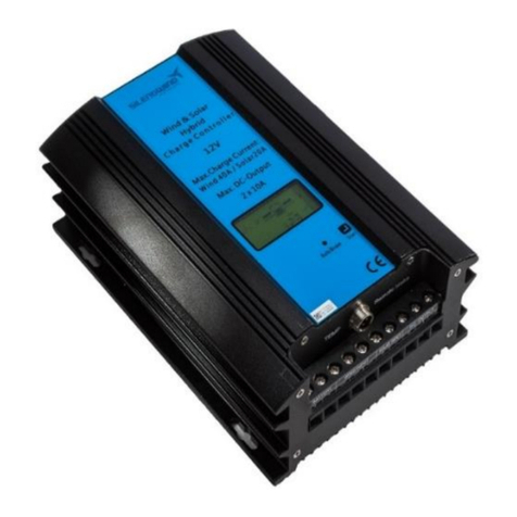
The Silentwind charge controller HYBRID BOOST is a combined wind and solar
charge controller with an inbuilt micro-controller. The HYBRID BOOST was especially
developed for the Silentwind Generator and enables you to additionally install solar
panels up to a wattage of 300 Watt peak or to a maximum current of 20A.
If you are using the ‘Load’ outputs, the charge controller can be configured to
automatically switch off those outputs before the batteries are too deeply discharged,
or turn on a light when it gets dark and turn off again when the sun rises.
Major operating parameters can be seen on an LCD on the front panel or all
parameters can be seen on a tablet or smartphone over the Bluetooth connection.
You can also set all operating parameters using the App provided for all Android and
iOSdevices.
The Silentwind Generator generates 3 phase AC voltage. In the charge controller AC
is converted to a DC voltage. There are different models: 12 / 24 or 48 depending on
the system voltage of the wind generator. All types of batteries (Gel, AGM, flooded
and sealed lead acid and also lithium) can be charged.
The correct maximum charge voltage - depending on the type of battery - must be
adjusted in the setup.
The charge-controller is
Advice:
Please keep in mind that all lead acid batteries can emit hydrogen which is a
dangerous explosive gas. If the place where you mount the charge controller is close
to these batteries, ensure adequate ventilation. Gel or AGM batteries are normally
maintenance free and should not emit gas if properly charged.
Always make sure the charge controller is mounted in a dry and as cool a place as
possible.

3
!
!
Contents:
1. Wiring diagram 4
2. Technical data 4
3. Components of the charge controller 5
3.1 Bottom panel connections 5
3.2 Front panel LCD 6
4. Mounting the charge controller 6
5. Cable size selection 8
6. Installation and Connection of the charge controller 8
7. External Stop Switch 10
8. Connecting solar panels 10
9. Programming charge controller 11
10. Programming instruction 12
10.1. Operating keys 12
10.2. Battery voltage and charge current 12
10.3. Charge cut-off voltage 13
10.4. Charge amount in kilowatt hours (kWh) 13
10.5. Current charging power wind 13
10.6. Current charging power solar 13
10.7 Consumer settings 14
10.8 Brake adjustments 15
10.9 Night lamp parameters 15
11. Troubleshooting 17

4
!
!
1. Wiring Diagram
2. Technical data
Hybrid-charge controller type
HYBRID BOOST
Battery system voltage (automatically detected)
12 / 24 / 48 Volt
Maximum power input from the windgenerator
600 W
Maximum current input from the windgenerator
40A / 30A / 15A
Maximum power input from solar panels
300W
Maximum current input from solar panels
20A / 10A / 5A
Maximum open circuit voltage input of the solar panel
50V DC
Maximum charging current to batteries
60 A
Maximum switch off current at LOAD output (Load)
2 x 10 A
Voltage adjustable for the batterytypes
flooded, sealed, gel or AGM
!
!
Dimensions (L x W x H) in mm
220 x 150 x 82
Weight
2,80 kg
Suitable for
flooded, sealed, gel or AGM
Warranty
24 months
Features
Cable connection
screw terminals
Integrated electronic brake
charge limitation, storm
brake
Integrated manual brake switch
service
LCD of all relevant workingdata
W, A, V/Ah, kWh, Ah
External stop switch
Plug connector

5
!
!
3. Components of the chargecontroller
3.1 Bottom panel
On the bottom of the charge controller there are screw terminals to connect the
battery, the wind generator, the solar panels and DCoutputs.
The connections for the remote brake are alsobelow.
Bottom panel:

6
!
!
3.2 LCD
On the front of the charge controller there is an LCD that shows you all operating
data during the workingprocess.
4. Mounting the charge controller
The charge controller generates heat and should be mounted with the panel upright (if
you can read the front panel text horizontally then this is correct). The side panels and
back panel are a heat sink to dissipate heat, which is why the orientation is important.
The charge controller is mounted to the wall using four screws.

7
!
!
5. Cable size selection
As you can see from the wiring diagram in paragraph 1 a 3-pole cable with suitable
cross section must be wired from the Silentwind Generator to the charge controller.
The charge power gets from the charge controller to the batteries through two wires
whereas on the AC input is three wires. Therefore the cross section of the two wires
on the DC output should be greater; we recommend a minimum cross section of
10mm2.
See below table to find the correct cable cross section:
System voltage 12 Volt
Distance from wind
generator to the charge
controller in m
0 - 9
10 – 19
20 – 29
30 – 44
45 – 69
70 – 110
Cable cross sectionmm2
AWG
6
10
10
8
16
6
25
4
35
2
50
1
Distance from the charge
contr. to the battery in m
0 - 9
10 – 19
20 – 29
30 – 44
45 – 69
70 – 110
Cable cross sectionmm2
AWG
16
6
25
4
35
2
---
---
---
---
---
---
System voltage 24 Volt
Distance from wind
generator to the charge
controller in m
0 - 9
10 – 19
20 – 29
30 – 44
45 – 69
70 – 110
Cable cross sectionmm2
AWG
2.5
14
4
12
6
10
10
8
16
6
25
4
Distance from the charge
contr. to the battery in m
0 - 9
10 – 19
20 – 29
30 – 44
45 – 69
70 – 110
Cable cross sectionmm2
AWG
16
6
25
4
35
2
---
---
---
---
---
---
6. Installation and connection of the chargecontroller:
The charge controller should be mounted close to the battery in a ventilated and cool
location, which enables you to read the information shown on the LCD and to operate
the manual brake switch easily. There is a remote brake switch which can be used if
the charge controller is not easily accessible.
Safety advice:
Especially acid batteries can emit gas when charging. Therefore the charge controller
must not be installed close to those batteries. In case of high concentration of
dangerous gas there is a risk of explosion. Please note the safety regulations and
advice of the batterymanufacturer.
If the acid batteries are equipped with ventilation pipes to the exterior or if the storage
room of the batteries is otherwise ventilated, the charge controller can be installed
close to the batteries.

8
!
!
Please find a sketch of the wiring diagram in the paragraph 1 of this manual.
Make sure that you fix the wires properly to prevent them from getting loose
due to vibrations. Use correct size ferrules on all stranded wire into the charge
controller. Fix the screws sufficiently to ensure electriccontact.
Crimp each wire from the wind generator with a suitable sized ferrule and then screw
those into the terminals of the charge controller. The use of crimp ferrules is highly
recommended on stranded wire as this makes better contact with the screw terminals
of the charge controller.
It is critical that you connect the charge controller to the battery using the
correct polarity before connecting the wind generator.
Please connect a suitable fuse (70 Amp. or more) close to the battery in the positive
wire. This is to protect your boat from damage if there a fault develops in the charge
controller and power is flowing back from the batteries to the charge controller.
Please take note:
After you have connected the battery you can connect the Silentwind generator, the
solar panels and, if required, connections to the load outputs with maximum 10A. On
the 3-phase output wires of the Silentwind you do not need to pay attention to
polarity.
Attention: Confusing the Positive and Negative connections will destroy your
charge controller. In that case warranty is voided.
If there is sufficient wind speed when connecting the Silentwind Generator, this will
immediately generate electric power at the end of the 3 AC wires without being
connected to the charge controller. Therefore we recommend blocking the Silentwind
Generator blades with a rope before connecting the wires to the charger. The 3 AC
output wires must be connected to the 3 screw terminals on the bottom the charge
regulator. (See paragraph 3.1).
In case you want to connect additional solar power (max. 300W) to the charge
controller, this should be done by using the PV screw terminals.
Please make always sure that you connect the solar panels with the correct polarity.
You can find the connection diagram in paragraph8.

9
!
!
7. External Stop Switch
You can connect an external stop switch to the charge controller (see picture on
page 5). You can choose the type of stop switch suitable to your instrumentpanel.
8. Connecting solar panels
The charge controller Hybrid BOOST is a hybrid controller both for wind and solar
energy. Solar panels with a max power of 300 Wp ( 20 A for 12V / 10 A for 24V and 5
A for 48V) can be connected, See technical details page4.
Connect the solar panels according to the followingsketch.
12 volt system:
24 volt system:

10
!
!
9. Programming the charge controller
Before using the charge controller it must be adjusted to the type of battery (flooded,
gel, AGM) you want to use, the Storm brake and the absorption modus according to
your system.
A special feature of this charge controller is that you can very easily programme
everything through your Smartphone or Tablet. Download the App for your operating
system (Android or iOS) from our website (Android) or on the Apple App Store (iOS).
When the batteries are fully charged (they reach the ‘Over voltage’ set for the type of
battery using the App) the charge controller will switch off the Silentwind generator.
The maximum charging current for your battery type can also be adjusted. You
programme the maximum charging current using the ‘Brake Current’ in the App.
We also recommend making use of the other additional adjustments according to
your individual requirements, like the switch on and switch off voltage for the load
settings and light function.
If batteries are fully charged (reach ‘Over voltage’) or maximum charging current is
reached, the Silentwind Generator will stop for approx. 5 minutes.
The brake mode of the charge controller generates heat inside the charge controller
which are carefully monitored by the micro controller. Therefore the break time of the
Silentwind Generator will be increased in high wind speeds until the internal
temperature is reduced by dissipation.
For this reason the charge controller should be installed on a place as cool as
possible. Never install the controller at direct solar radiation orsunlight.
This means that the Silentwind Generator can also be operated with a large battery
bank. If a larger battery bank is discharged, a higher charge current will flow in high
wind speeds. As you can set the maximum charge current you can prevent
overheating of the charge controller. As described in ‘Brake Current’ configuration
you can reduce the maximum charge current according to the requirements.
Advice:
If the capacity of the batteries is less than 150 Ah, or old batteries have lost their
original capacity, the point of maximum Voltage can be reached very fast although
the battery is not fully charged yet. In this case it can be useful to connect an electric
consumer to the Load output, as this will reduce the voltage and thus prevent that the
break mode is activated tooearly.

11
!
!
Searching
device
10. Programming instruction
10.1 APP Download
For Android devices please go to our website under following link:
http://www.silentwindgenerator.com/en/downloads and download the APP Win-
Power directly to your Smartphone or Tablet.
For iOS devices, please go to the Apple App Store and search for Win-Power.
Download the App directly to your iPhone or iPad.
10.2 Settings
Open the App on your device. You will be requested to enable the Bluetooth.
Go to ‘Searching Device’
Check all Bluetooth devices and choose the one for your system. For Android choose
‘win-power’. For iOS choose ‘iOSwin-power’.
Go to ‘Connect Device’
The password for the connection is ‘1234’.

12
!
!
9.2.1 Setting parameters
Go to menu key on your device and then ‘Data Setting’
9.2.2 Charging - Absorption mode
In the setup field ‘Unload Volts’ shown above you can set the voltage for the
absorption mode of your batteries by clicking on the field and change the value.
Usually this stage is to slowly keep charging the batteries until the maximum charge
voltage is reached. The value depends on the system voltage (12/24/48V). The
approximate values are 5% less than the maximum charge voltage. For instance
for a charge end voltage of 14.4V (12V system) the value should be 13.4V

13
!
!
9.2.2 Brake adjustment
You can set the maximum current when you want to stop the Silentwind Generator.
This prevents overheating, especially with big battery banks and high loading
currents. This function can also be used to reduce the RPM of the Silentwind
Generator.
You can calculate the maximum charge current value as follows: The maximum
power of the Silentwind Generator (400 Watts for the 12V wind generator) divided by
the maximum cut-off voltage e.g. 14.4 Volt at a AGM battery. The maximum possible
charge current in this example is therefore 400VA / 14.4V = 27.7Amp.
9.2.3 Boost function
With this parameter you can set the Boost to achieve an earlier start of charging in to
the batteries. The recommended valuesare:
12V – 2.0 V
24V – 4.0 V
48V – 8.0 V
9.2.4 Charge cut-off voltage
In the display mode shown above ‘Overvoltage’ you can set the maximum charge
voltage for your battery type. Please note the instructions of the manufacturer of the
batteries. The maximum possible voltage is dependent on the system voltage
(12/24/48V) and the type of battery (Acid, Gel, AGM or Lithium). For instance 12V-
AGM battery: approximately 14.4V.

14
9.2.5
Save settings
!
!
Click on ‘Save Data’ to save the settings.
Saftey advice:
Please never disconnect the battery wires while the Silentwind Generator is charging.
This will immediately destroy the charge controller. If you want to measure the
charging current flowing, an amp meter must be installed in the positive battery wire.
Ensure the correct polarity for the amp meter. However, the actual charging current
flowing can be seen on theLCD on the front panel.

15
!
!
11. Troubleshooting
The blades of your Silentwind Generator are turning too slowly
•The manual stop switch of the charge controller is in‘BRAKE’ position.
•Connecting the wind generator wires possibly caused a short circuit
between thewires.
•The wind speed is too low.
•The fuse connected to the battery isgone.
•Your Silentwind Generator or the charge regulator has an internal problem.
Please contact your dealer.
In order to find the problem you have to check the installation from wind generator
through to battery.
•Disconnect the three wires wind generator form the charge controller. If the
Silentwind Generator now does start the failure is between charge controller
and the battery. BE CAREFUL not to touch the end of the cables because of
the electric power that occurs at these ends.
•If the Silentwind Generator continues to turn slowly, the problem is between
charge controller and Silentwind Generator. Check there are no shorts
between the wires connecting the wind generator and the charge controller.
•Ensure the recommended cross section of the wire as well as the
recommended minimum capacity of the battery that you want to charge.
If the Silentwind Generator generates too little power
•The wind speed is too low, see the performance diagrams shown in the
manual of the Silentwind. The wind speed measured on top of the mast is
usually higher than at the position of the windgenerator!
•Turbulences by obstacles in the wind direction or the locationis
unsuitable, mast too short.
•The wire cross section is correct for the length of the wires installed.
(see page 3).
•The battery capacity is below 100Ah so that the maximumpossible
voltage is reached too qiuickly.
•The battery is too old and has lost capacity so that the maximum power
voltage is reached too qiuickly.
Enjoy collecting regenerative power. You contribute protecting the
environment and saving your money !
Your Silentwind Team

16
!
!
Rulis Eléctrica, Lda.
Loteamento Industrial de Linhares, Lote19
PT-4805-486 Santo Estevão de Briteiros / Guimarães
Portugal
VAT/Contribuinte / EORI-N. PT 502 995 530
Tel. 00351-253-572763
Fax 00351-253-572764
Tm/Handy 00351 96 790 79 33
e-mail: [email protected]
site: www.silentwindgenerator.com
Other manuals for HYBRID BOOST
1
Table of contents
Other SilentWind Controllers manuals
Popular Controllers manuals by other brands
Nexxt Solutions
Nexxt Solutions NHA-B100 manual
Gira
Gira KNX 213900 operating instructions
Grape Solar
Grape Solar GS-PWM-20A user manual
Dometic
Dometic Go Power GP-PWM-10-SQ user manual
Xantrex
Xantrex Freedom Sequence owner's manual
Johnson Controls
Johnson Controls FEU2610 Series installation instructions
