SILICYCLE MiniBlock User manual

www.SiliCycle.com
SiliCycle MiniBlock®
User Guide

SiliCycle MiniBlock® User Guide
2www.SiliCycle.com | inf[email protected]om
1. Usage and Safety Precauons . . . . . . . . . . . . . . . . . . . . . . . . . . . . . . . . . . . . . . . . . . . . . . . . . . . . . . . . . . . . . . . . . . 6
Cleaning .................................................................................................... 6
Maintenance ............................................................................................... 6
Storage ..................................................................................................... 6
Temperature ................................................................................................ 6
Pressure .................................................................................................... 6
Components ................................................................................................ 6
Document Convenons ...................................................................................... 6
2. General .................................................................................... 7
2.1. The SiliCycle MiniBlock Reacon Tubes .................................................................... 8
2.2. SiliCycle MiniBlock Conguraons ....................................................................... 10
2.2.1. Ambient Temperature Conguraons ............................................... 11
2.2.2. Plugs for Unused Pinch-Tube Inserts ................................................ 11
2.2.3. Controlled Temperature Conguraons ............................................. 11
2.2.4. Combining Red and Blue SiliCycle MiniBlocks Into 96-Well Format ....................... 12
2.3. SiliCycleMiniBlock System Materials .................................................................... 12
2.3.1. SiliCycle MiniBlock Metal Components .............................................. 12
2.3.2. Reacon Tube Materials .......................................................... 12
2.3.3. Pinch-Tube Insert Materials ....................................................... 12
2.3.4. Septa Materials ................................................................. 13
2.4. SiliCycleMiniBlock Temperature Control ................................................................. 14
2.5. SiliCycle MiniBlock Reacons Requiring an Inert Atmosphere .............................................. 15
3. SiliCycle MiniBlock Assembly and Reacon Setup ................................................ 16
3.1. Pre-Assembly Checks .................................................................................. 16
3.2. SiliCycle MiniBlock Assembly ........................................................................... 18
3.2.1. Setup for Ambient Temperature Reacon ............................................ 18
3.2.2. Setup for Controlled Temperature Reacon .......................................... 18
3.2.3. Inserng Reacon Tubes .......................................................... 19
3.2.4. Sealing for Reacons Not Requiring Inert Condions .................................. 20
3.2.5. Sealing for Reacons Requiring Inert Condions ...................................... 22
3.2.6. Closing the SiliCycle MiniBlock Valve ................................................ 23
4. Reacon Setup, Mixing and Incubaon ......................................................... 24
4.1. Resin Addion – Solid-Phase Reacons .................................................................. 24
4.1.1. Resin Addion – Serial ........................................................... 24
4.1.2. Resin Addion – Parallel .......................................................... 24
4.1.3. IRORI® Kans™ ................................................................... 24
4.1.4. Resin Swelling .................................................................. 24
4.2. Inert Atmosphere ..................................................................................... 24
4.3. Adding Solvents and Reagents .......................................................................... 25
4.4. Reacon Mixing and Incubaon ........................................................................ 26
4.4.1. Shaking Staons ................................................................ 26
4.4.1.1. Securing SiliCycle MiniBlocks on the Shaking Staon ................................. 26
4.4.1.2. Balancing the Shaking Staon .................................................... 26
4.4.1.3. Pre-Operaonal Shaking Staon Check ............................................ 27
4.4.1.4. Seng Agitaon Speed ......................................................... 28
4.5. Incubaon ............................................................................................ 28
4.5.1. Aaching the Manifold to the Shaker ............................................... 28
4.5.2. Connecng to the Recirculator . . . . . . . . . . . . . . . . . . . . . . . . . . . . . . . . . . . . . . . . . . . . . . . . . . . . . 29
4.5.3. Tesng the Recirculaon System ................................................... 29

3
5. Washing, Puricaon and Product Collecon .................................................... 30
5.1. Solvent Removal and Resin Washing .................................................................... 30
5.1.1. Removing Solvents to Waste on the Shaking Staon ................................... 30
5.1.2. Accelerang Solvent Drainage ..................................................... 30
5.1.2.1. Air Push Assist Device .......................................................... 31
5.1.2.2. Posive Pressure Manifold ...................................................... 31
5.1.2.3. Inert Atmosphere Manifold ...................................................... 32
5.1.3. Washing ....................................................................... 32
5.2. Puricaon and Clean-Up .............................................................................. 32
5.2.1. Solid-Phase Extracon ( SPE)....................................................... 32
5.2.2. Scavenger Resins ................................................................ 33
5.3. Product Collecon / Cleavage ........................................................................... 33
5.3.1. Collecon Rack Selecon ......................................................... 34
5.3.2. Collecon Vessel Posioning ...................................................... 37
6. Maintenance .............................................................................. 39
6.1. Cleaning Procedure .................................................................................... 39
6.1.1. Post-Collecon Rinse ............................................................. 39
6.1.2. SiliCycle MiniBlock Cleaning ....................................................... 40
6.2. Replacing Consumable Components .................................................................... 40
6.2.1. Replacement of Pinch-Tube Inserts ................................................. 40
6.2.2. Replacement of Compression Cords ................................................ 42
7. Troubleshoong ............................................................................ 43
7.1. Jammed Slide Valve ................................................................................... 43
7.2. Leakage / Solvent Loss ................................................................................. 43
7.3. Prevenve Maintenance ............................................................................... 45
Appendix A: Heat Shrinking Teon® Sleeves Onto Glass Reacon Tubes ................................ 48
A.1. Apparatus ............................................................................................ 48
A.2. Procedure ............................................................................................ 48
A.3. Quality Checks ........................................................................................ 49
A.3.1. Incomplete Heat-Shrinking ........................................................ 49
A.3.2. Defecve Heat-Shrinking ......................................................... 49
Appendix B: Resin Dispenser: Operang Instrucons ............................................... 50
B.1. Overview ............................................................................................. 50
B.2. Operaon Descripon ................................................................................. 50
B.3. Dispensing............................................................................................ 51
B.3.1. Resin Dispenser Setup ( Procedure wrien for the 48-Posions Version )................... 51
B.3.2. Dispensing Procedure ............................................................ 52
B.3.3. Dispensing to Microter / Deep Well Plates .......................................... 53
B.4. Resin Cleaning ........................................................................................ 54
B.5. Resin Dispenser Calibraon ............................................................................ 54
Appendix C: SiliCycle MiniBlock Collecon Rack Conguraons ....................................... 55
C.1. Assembly Diagrams .................................................................................... 56
Appendix D: Determining Correct Collecon Tube Height ............................................ 58
D.1. Instrucons for the Go/No-Go Test ...................................................................... 58
Appendix E: Chemistry Applicaons .............................................................. 59
Procurement ................................................................................ 59
SiliCycle MiniBlock® User Guide
4www.SiliCycle.com | inf[email protected]om
Figures
Figure 1: SiliCycle MiniBlock ..................................................................... 7
Figure 2: Reacon Tube Components ............................................................. 8
Figure 3: SiliCycle MiniBlock Components .......................................................... 8
Figure 4: Glass Reacon TubeWith Teon® Heat Shrink Sleeve ......................................... 8
Figure 5: Types of Pinch-Tube Inserts .............................................................. 9
Figure 6: Valve Mechanism in Closed Posion ...................................................... 9
Figure 7: SiliCycle MiniBlock with Valve Key ........................................................ 9
Figure 8: Reacon Tube Conguraons ........................................................... 10
Figure 9: Red Plugs Conguraons ............................................................... 11
Figure 10: SiliCycle MiniBlock Heat Transfer Blocks ................................................. 11
Figure 11: Collecon conguraon 96-Posions .................................................... 12
Figure 12: SiliCycle MiniBlock with Heat Transfer Block .............................................. 14
Figure 13: Inert/Purge Manifold ................................................................. 15
Figure 14: Slide Valve Operaon ................................................................. 16
Figure 15: Inspecng Pinch-Tubes ............................................................... 17
Figure 16: Pinch-Tube Extension . . . . . . . . . . . . . . . . . . . . . . . . . . . . . . . . . . . . . . . . . . . . . . . . . . . . . . . . . . . . . . . . . 17
Figure 17: AlignmentsPlates Installed ............................................................ 18
Figure 18: Heat Transfer Block Installed ........................................................... 19
Figure 19: Insert Reacon Tubes ................................................................ 19
Figure 20: Male / Female Luer Fing ............................................................ 20
Figure 21: Seang Reacon Vessels .............................................................. 20
Figure 22: Septum Layer and Cover Plate ......................................................... 21
Figure 23: Inert / Purge Manifold ................................................................ 22
Figure 24: SiliCycle MiniBlock With Valve Key ...................................................... 23
Figure 25: Dispensing Plate ..................................................................... 24
Figure 26: Shaking Staons ..................................................................... 26
Figure 27: Aligning SiliCycle MiniBlocks on the Shaker Top ( With Oponal Recirculator Manifold )........... 27
Figure 28: Securing SiliCycle MiniBlocks on the Shaker Top ........................................... 27
Figure 29: Aaching the Recirculator Manifold to the Shaker Top ..................................... 28
Figure 30: Slide Valve Operaon ................................................................. 30
Figure 31: Air Push Assist Device ................................................................ 31
Figure 32: Posive Pressure Manifold ............................................................ 31
Figure 33: Transfer to Second SiliCycle MiniBlock Containing SPE Packed Tubes ( Using Transfer Adapter ).....32
Figure 34: Examples of SiliCycle MiniBlock Collecon Racks and Plates ................................. 33
Figure 35: Collecng Products .................................................................. 34
Figure 36: Vacuum Collecon Base, Shown With a 24-Posions Rack .................................. 34
Figure 37: Proper Height Alignment for Collecon Tubes ............................................ 37
Figure 38: Posioning SiliCycle MiniBlock Components For Collecng Into 48 Test Tubes Rack .............. 38
Figure 39: Pinch-Tube Extension . . . . . . . . . . . . . . . . . . . . . . . . . . . . . . . . . . . . . . . . . . . . . . . . . . . . . . . . . . . . . . . . . 38
Figure 40: Tube Removal Tool ................................................................... 39
Figure 41: Remove Valve Insert Lock-Plate ........................................................ 41
Figure 42: Remove Pinch Tube Inserts ............................................................ 41
Figure 43: Compression Cords Replacement ....................................................... 42
Figure 44: Leakage Points ...................................................................... 43
Figure 45: Exploded View of SiliCycle MiniBlock Reactor ............................................. 46

5
Figure 46: Glass Reacon Tube with Teon® Sleeve ................................................. 48
Figure 47: Resin Dispensing Plate ................................................................ 50
Figure 48: Resin Dispenser ( 13742086)........................................................... 51
Figure 49: Resin Dispenser Closed Posion ........................................................ 52
Figure 50: Resin Dispensing Spreader ............................................................ 52
Figure 51: Dispensing Powder .................................................................. 53
Figure 52: Replacing the Plate .................................................................. 54
Figure 53: The Vacuum Collecon Base Set ( 13742008)............................................. 55
Figure 54 : 12 x 100 mm Test Tubes ( 8 mL)........................................................ 56
Figure 55 : 12 x 75 mm Test Tubes ( 6 mL)......................................................... 56
Figure 56 : Deep Well Plate ( Various Volumes )..................................................... 56
Figure 57 : Tall Minitube Rack ( 2.5 mL)........................................................... 56
Figure 58 : 16 x 100 mm Test Tubes ( 15 mL)....................................................... 57
Figure 59 : 15 x 45 mm Vials (3.7 mL)............................................................. 57
Figure 60: 17 x 61 mm Vials (7.5 mL) ............................................................ 57
Figure 61 : 21 x 70 mm Vials (15 mL)............................................................. 57
Figure 62 : 28 x 95 mm Vials ( 40 mL)............................................................. 57
Figure 63: Tube Heights are Correct. “GO” ........................................................ 58
Figure 64: Tube Heights are too Low. “NO-GO” .................................................... 58
Figure 65: Tube Heights are too High. “NO-GO” .................................................... 58
Tables
Table 1: MinBlock Physical Descripon ............................................................ 7
Table 2: SiliCycle MiniBlock Conguraons ........................................................ 10
Table 3: SPE Development Kits Available from SiliCycle .............................................. 33
Table 4: Collecon Plates, Racks and Vessels ...................................................... 36
Table 5: SiliCycle MiniBlock Spare Parts .......................................................... 47
Table 6: Standard Conguraons ................................................................ 51
Table 7: High Volume Kit ( Sold Separately )........................................................ 51
Table 8: Collecon Rack Conguraons ........................................................... 55
SiliCycle MiniBlock® User Guide
6www.SiliCycle.com | inf[email protected]om
1. Usage and Safety Precauons
The SiliCycle MiniBlock products for parallel synthesis are intended for use by persons skilled in chemical handling and synthesis. Best results with
the SiliCycle MiniBlock can be achieved by following the usage, maintenance and storage guidelines in this Operaons Manual.
SiliCycle MiniBlock products include a 12 month warranty. This warranty is conngent on proper usage and maintenance as described in this
manual. If instrucons contained in this manual are not followed, the warranty may be invalidated. Some of the common consideraons for opmal
SiliCycle MiniBlock use include:
Cleaning
All chemicals should be cleaned from the SiliCycle MiniBlock as soon as possible. Full cleaning of the SiliCycle MiniBlock is recommended
immediately aer synthesis.
Maintenance
SiliCycle MiniBlocks should be checked and consumable components replaced as part of a scheduled maintenance program.
Storage
SiliCycle MiniBlocks should be stored with the slide (drainage) valve in the open posion and the two side clamps le undone.
Temperature
Reacon temperatures are limited to 80°C unless high temperature components are obtained from SiliCycle. Reacon temperatures must be
achieved using the apparatus described in this manual.
Pressure
SiliCycle MiniBlocks are not designed to withstand pressure build-up. Care should be taken to avoid pressure build-up when designing SiliCycle
MiniBlock synthesis procedures.
Components
Use only SiliCycle MiniBlock components purchased from, or approved by SiliCycle.
Document Convenons
The SiliCycle MiniBlock reactor is the central plaorm in SiliCycle’s advanced system for parallel
synthesis. SiliCycle MiniBlock reactors can be used to yield synthesis products for either high-throughput
or larger volume applicaons.
WARNING : is used to indicate the presence of a hazard which can cause personal
injury or death.
CAUTION : is used to indicate a potenal for damage to equipment
or synthesis results.
TECH TIP : is used to explain a product or operaonal nuance for a more eecve use of
the SiliCycle MiniBlock system.
7
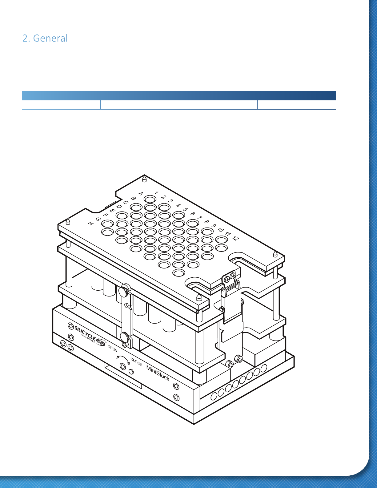
2. General
The SiliCycle MiniBlock is designed to enable the chemist to achieve maximum product yield and purity,
while minimizing the potenal for cross-contaminaon.
The SiliCycle MiniBlock’s patented valve mechanism enables simultaneous boom drainage of all reacon vessels, aided by the use of vacuum
and pressure. Reacon products are then transferred into collecon vessels, or SPE tubes for puricaon.
Ancillary components are used to achieve reacon agitaon and temperature control for the SiliCycle MiniBlock system.
Height Width Depth Weight
5” (13 cm)7” (18 cm)5” (13 cm)6.4 lbs (2.9 kg)
Table 1: MinBlock Physical Descripon
Figure 1: SiliCycle MiniBlock

6
5
4
3
2
1
SiliCycle MiniBlock® User Guide
8www.SiliCycle.com | inf[email protected]om
2.1. The SiliCycle MiniBlock Reacon Tubes
SiliCycle MiniBlock Reacon Tubes are designed as simple yet robust vessels for chemical synthesis. They consist of glass or polypropylene reacon
tubes containing a 20 μm frit for solids ltraon.
Figure 2: Reacon
Tube Components
Figure 3: SiliCycle
MiniBlock Components
Polyethylene
Reacon Tube Cover Plate
Septum Layer
Upper Alignment Plate
Lower Alignment Plate
Blue Teon®
Heat Shrink Sleeve
Large Alignment Pin
Small Alignment Pin
Reacon Tube
20 µm Frit
Pinch Tube
Female Luer Fing
Male Luer Fing
Glass reacon tubes also have a Teon® heat shrink sleeve at the luer p to improve sealing. When using toluene, or other solvents to which
polypropylene is not fully resistant, glass reacon tubes should be used instead.
Figure 4: Glass Reacon Tube
With Teon® Heat Shrink Sleeve

0.5 0.50.5
9
Pinch-Tube Inserts are available in PFA Teon®. PFA Teon® inserts can be used at high temperatures, PFA ngs also provide good chemical
resistance, parcularly to toluene. (Figure 5).
The Reacon Tubes are sealed at the boom by compressing the Pinch-Tubes, which project through the SiliCycle MiniBlock (Figure 6). This closure
is achieved for all Reacon Tubes simultaneously with a single turn of the T-handle valve key (Figure 7).
Reacon Tube
PFA Teon ©
Grey Fings
Figure 6: Valve Mechanism
in Closed Posion
Figure 7: SiliCycle MiniBlock
with Valve Key
Figure 5: Types of Pinch-Tube Inserts
SiliCycle MiniBlock® User Guide
10 www.SiliCycle.com | inf[email protected]om
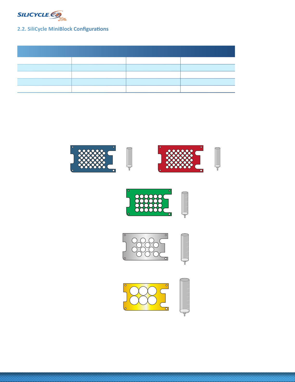
2.2. SiliCycle MiniBlock Conguraons
The base SiliCycle MiniBlock comes as standard with 48 female luer ngs in the base. SiliCycle MiniBlock can be adapted
to any of four basic conguraons:
Reacon Tubes
per SiliCycle MiniBlock
Reacon Tube
Volume (mL)Reacon Tube Material Collecon Format
48 (Blue Block)4Polypropylene or Glass 48 or 96 posions
48 (Red Block)4Polypropylene or Glass 48 or 96 posions
24 (Green Block)10 Glass 24 posions
12 (Silver Block)20 Glass 12 posions
6 (Gold Block)40 Glass 6 posions
Table 2: SiliCycle MiniBlock Conguraons
SiliCycle MiniBlock conguraons, together with the reacon tubes and color-coding are depicted in Figure 8.
Glass reacon tubes are provided with a blue Teon® heat-shrink sleeve at the luer p. This is to improve sealing against the female luer ng:
(Figure 4). Insert glass reacon tubes into Pinch-Tube Inserts gently and carefully to avoid snagging or damaging the Teon® heat-shrink sleeve.
Figure 8: Reacon Tube Conguraons
Blue
Silver
4 mL 4 mL
2
4
6
8
10 mL
4
8
12
16
20 mL
5
10
15
20
25
30
35
40 mL
Red
Gold
Green
11
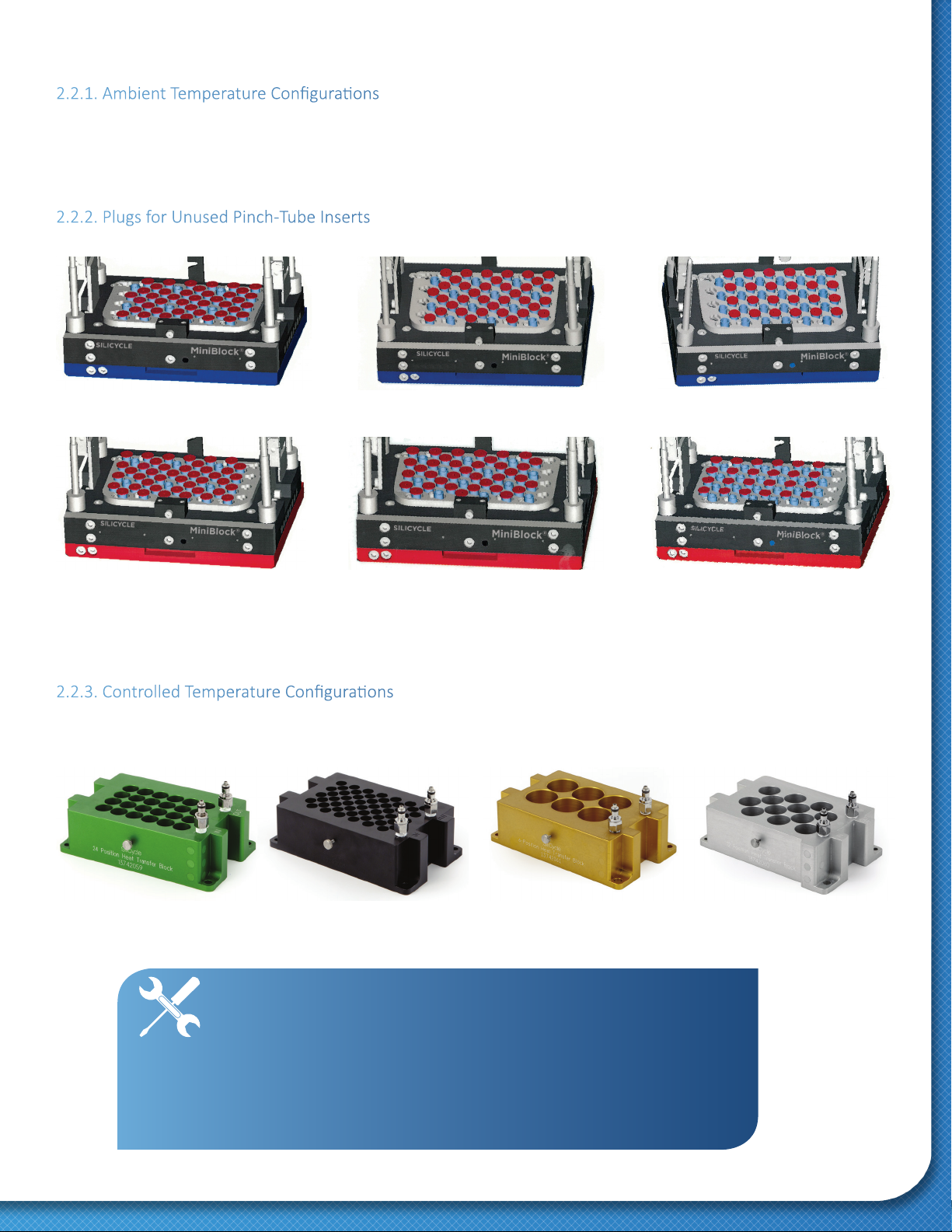
2.2.1. Ambient Temperature Conguraons
Converng SiliCycle MiniBlock volume conguraons for ambient temperature operaon requires:
• Proper Reacon Tubes
• Corresponding alignment and cover plates
These plates are color-coded (Figure 8) to enable ready idencaon of conguraon components. For 48-Posions SiliCycle MiniBlocks, Black
alignment plates are used for either a Blue or Red SiliCycle MiniBlock.
2.2.2. Plugs for Unused Pinch-Tube Inserts
Red plugs are used to ll unused female luer posions, to hold the vacuum applied beneath the SiliCycle MiniBlock when draining.
Figure 9: Red Plugs Conguraons
2.2.3. Controlled Temperature Conguraons
For temperature controlled reacons, heat transfer blocks are substuted for the alignment plates. The heat transfer blocks are color-coded, as are
the alignment plates, except for the black heat transfer block, which is used with either a Blue or Red 48-Posions SiliCycle MiniBlock. The basic
SiliCycle MiniBlock conguraons with the heat transfer blocks are depicted in Figure 10.
TECH TIP : The two (2) dierent 48-Posions SiliCycle MiniBlocks -
Red and Blue - are actually complementary conguraons.
A Blue block can be collected into half the posions
of a 96 deep well plate; the Red block can then be collected into the
intervening posions of the same 96 well plate (see Figure 11).
Alternavely, either the Red or Blue SiliCycle MiniBlocks
can be transferred into a 48-Posions collecon format.
Use a collecon block of corresponding Blue or Red
to assure proper transfer into the collecon vessels.
Figure 10: SiliCycle MiniBlock Heat Transfer Blocks
Blue block, 6-Posions Blue block, 24-Posions
Blue block, 12-Posions
Red block, 6-Posions Red block, 24-Posions
Red block, 12-Posions

SiliCycle MiniBlock® User Guide
12 www.SiliCycle.com | inf[email protected]om
2.2.4. Combining Red and Blue SiliCycle MiniBlocks Into 96-Well Format
Figure 11: Collecon conguraon 96-Posions
2.3. SiliCycle MiniBlock System Materials
The SiliCycle MiniBlock system is designed and constructed using high quality materials. Understanding of SiliCycle MiniBlock materials is important
when selecng SiliCycle MiniBlock components for a given chemistry.
2.3.1. SiliCycle MiniBlock Metal Components
SiliCycle MiniBlocks are primarily constructed of anodized aluminum and stainless steel. Given proper handling and prompt cleanup of corrosive
or deposit-forming compounds, these materials are very resistant to chemicals and physical wear.
2.3.2. Reacon Tube Materials
4 mL and 10 mL SiliCycle MiniBlock Reacon Tubes are available in either polypropylene or glass. The polypropylene tubes contain high quality
polyethylene frits (average porosity: 20 μm). All glass Reacon Tubes (4, 10, 20 and 40 mL) have 20 μm average porosity frits. Glass reacon tubes
also have a Teon® heat shrink sleeve at the luer p to improve sealing. When using toluene, or other solvents to which polypropylene is not fully
resistant, glass reacon tubes should be used instead.
2.3.3. Pinch-Tube Insert Materials
Pinch-Tube Inserts are available in PFA Teon®. PFA Inserts can be used at high temperatures, when other high temperature components are used.
PFA ngs also provide best chemical resistance, parcularly to toluene. (Figure 5).
Red Reactor
52-Posions
48 Used
96-Well
Collecon Plate
Blue Reactor
13
2.3.4. Septa Materials
The septa used to cover and seal the tops of SiliCycle MiniBlock reactors serve a number of dierent funcons.
They provide:
• Sealing of the Reacon Tubes to minimize evaporaon.
• Uniform compression of the Reacon Tubes to seal the Pinch-Tube Insert luer ngs.
• Septum piercing for reagent addion.
Septa for MiniBlock Top Plate:
• Mul-layer (13820118) – excellent chemical resistance, reduced solvent evaporave loss, readily pierced by automaon. This is the
recommended septum for most applicaons, except those exceeding 80°C.
• Silicone Mul-Layer Septa (13742080) - for reacons requiring high temperatures, up to 160°C.
TECH TIP: SiliCycle MiniBlocks are not designed for pressurized reacons. Do not
perform synthesis at or above solvent boiling points. Pressure buildup
resultant from synthesis can be avoided using an Inert
Atmosphere Manifold (See Secon 3.2.5 Sealing
For Reacons Requiring Inert Condions).
CAUTION: Hot toluene can damage polypropylene. Hot toluene should be used with
glass reactor tubes and PFA Pinch-Tube Inserts.
WARNING: SiliCycle MiniBlock applicaons are limited to a maximum temperature of
80°C, unless high temperature components are used. Consult SiliCycle for
informaon regarding applicaons over 80°C.

SiliCycle MiniBlock® User Guide
14 www.SiliCycle.com | inf[email protected]om
2.4. SiliCycle MiniBlock Temperature Control
Reacon temperatures are adjusted on the SiliCycle MiniBlock using a Heat Transfer Block, which ts closely around each reacon tube (Figure 12).
Heat transfer uid is recirculated through the anodized aluminum Heat Transfer Block, with heat transmied eciently.
A dierent Heat Transfer Block is required for each of the four basic SiliCycle MiniBlock conguraons (48, 24, 12 and 6-Posions) (Figure 10).
Heat Transfer Block
Locking Arm Large Alignment Pin
Small Alignment Pin
Quick Disconnect Fing
Septum Layer
Cover Plate
Figure 12: SiliCycle MiniBlock with Heat Transfer Block
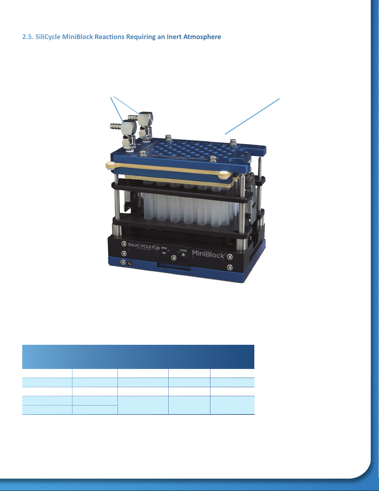
Outlets Inert/Purge Manifold (48-posions)
15
2.5. SiliCycle MiniBlock Reacons Requiring an Inert Atmosphere
For air and / or moisture sensive reacons, the SiliCycle MiniBlock can be ed with an Inert Atmosphere Manifold (Figure 13).
This manifold has a natural rubber septum inside, providing inert gas to individual reactor tubes.
The Inert Gas Manifold septum can also be pierced at each reactor posion with a syringe, without compromising the inert condions
in the reactors.
Figure 13: Inert/Purge Manifold
MiniBlock Format Inert Manifold PN Internal Septum PN
Sealing Gaskets (Bottom Gasket)
Rubber PN Mul-Layer PN
6-posions 13200957 13742152 13200992 13201040
12-posions 13200951 13742169 13200993 13201041
24-posions 13200950 13742170 13200994 13201042
48-posions Red 13742182 13200080 13200079 13200081
48-posions Blue 13742183
SiliCycle MiniBlock® User Guide
16 www.SiliCycle.com | inf[email protected]om
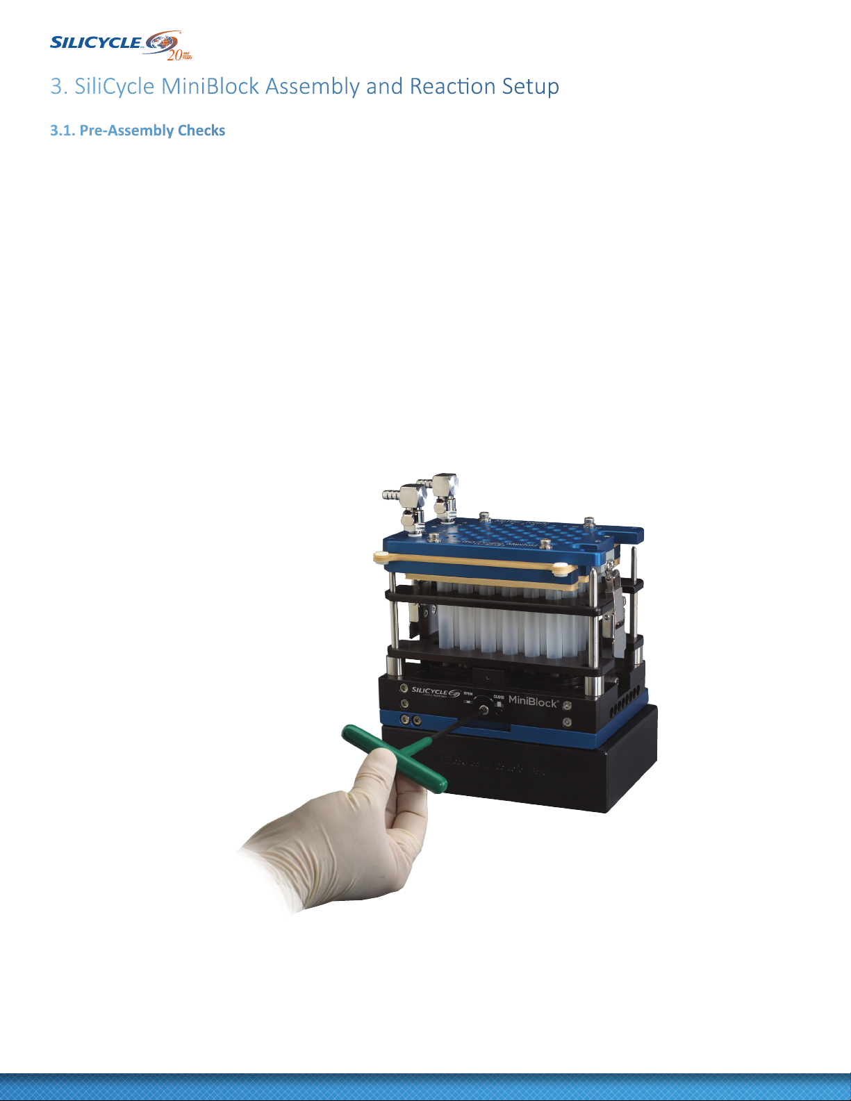
3. SiliCycle MiniBlock Assembly and Reacon Setup
3.1. Pre-Assembly Checks
1. With no reactor tubes inserted, make sure the SiliCycle MiniBlock is clean and that plugs are inserted in Pinch-Tube Inserts for unused posions.
The Pinch-Tube Inserts should be inserted uniformly ush to the base of the SiliCycle MiniBlock. The «keyhole» alignment plate should be secured
to x the posion of all Pinch-Tube Inserts. See secon 6.2.1 Replacement of Pinch-Tube Inserts for detailed instrucons.
2. Use the T-handle Valve Key (5/32’’ hex key) to check that the valve mechanism slides freely (Figure 14). Be certain that the SiliCycle MiniBlock has
been stored with the valve in the «open» posion. If the valve was closed, see secon 6 Maintenance before proceeding.
3. Inspect the Pinch-Tubes (the part of the Pinch-Tube Inserts which projects through the base of the SiliCycle MiniBlock) on the boom of the SiliCycle
MiniBlock (Figure 15). All Pinch-Tubes should be extending through the boom of the SiliCycle MiniBlock by 3-5 mm. (Figure 16.) This extension is
important to prevent cross-contaminaon in later transfer steps. Reinsert or replace any Pinch-Tubes that do not extend through the base properly.
See secon 6.2.1 Replacement of Pinch-Tube Inserts for detailed instrucons.
Figure 14: Slide Valve Operaon

17
Figure 15: Inspecng Pinch-Tubes
Figure 16: Pinch-Tube Extension
Tall Tube Extender
Spacer
3-5 mm
Collecon Base
SiliCycle MiniBlock® User Guide
18 www.SiliCycle.com | inf[email protected]om
3.2. SiliCycle MiniBlock Assembly
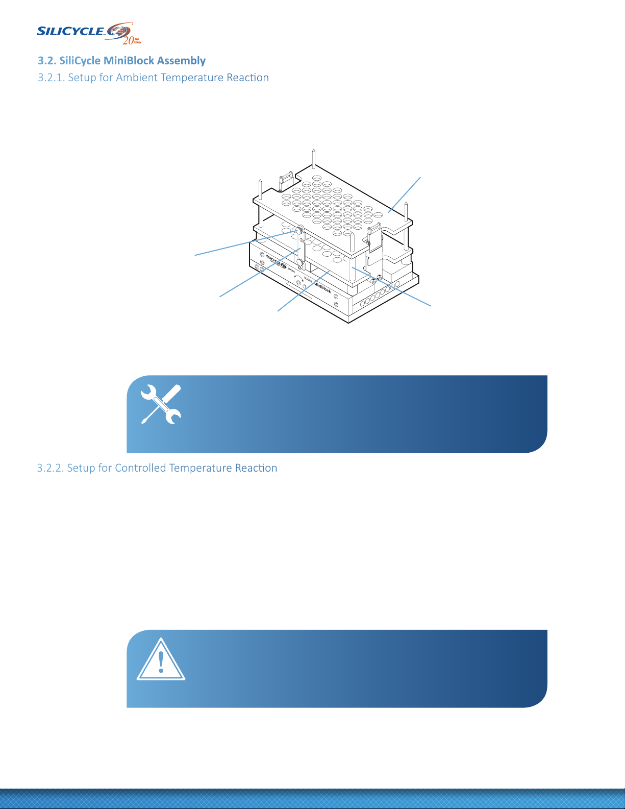
3.2.1. Setup for Ambient Temperature Reacon
1. Place the corresponding colored lower Alignment Plate on the SiliCycle MiniBlock, followed by the upper alignment plate (Figure 17). Note that
these plates have hole sizes corresponding to SiliCycle MiniBlock alignment pins, which make it possible to only posion the lower plate at the
boom and the upper Alignment Plate at the top.
2. Secure the Alignment Plates on either side of the SiliCycle MiniBlock, by turning front and back locking arms into posion and ghtening
thumbscrews.
Figure 17: Alignment Plates Installed
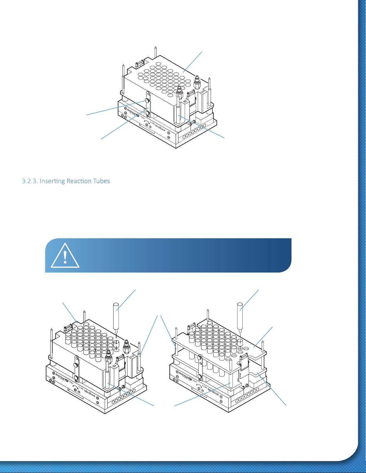
3.2.2. Setup for Controlled Temperature Reacon
1. With no alignment plates on the SiliCycle MiniBlock, place a Heat Transfer Block of the corresponding color over the Alignment Pins. Be sure to
orient the large alignment hole of the Heat Transfer Block with the large alignment pin on the SiliCycle MiniBlock.
Red and Blue SiliCycle MiniBlocks require a Black (48-Posions) Heat Transfer Block. The 24, 12 and 6-Posions SiliCycle MiniBlocks have color-coded
Heat Transfer Blocks (Green for 24-Posions, Silver for 12-Posions, Gold for 6-Posions).
2. Secure the Heat Transfer Blocks on either side of the SiliCycle MiniBlock, using front and back locking arms and thumbscrews (Figure 18).
TECH TIP: The SiliCycle MiniBlock has one large alignment pin, which prevents
installaon of the alignment plates in any way other than the intended
orientaon. Do not force the alignment plates or other SiliCycle MiniBlock
components onto the SiliCycle MiniBlock. Proper orientaon with respect to
the large alignment pin permits all components to slide on easily.
Upper Alignment Plate
Lower Alignment Plate
Thumb Screw
Front Locking Arm
Large Alignment Pin
WARNING: Keeping alignment plates or heat transfer blocks secured with the front
and back locking arms is important to safe operaon. Liing an unsecured
SiliCycle MiniBlock by the plates or heat transfer block could result in block
slippage and potenal chemical spillage or contact, as well as physical injury.
19
3.2.3. Inserng Reacon Tubes
1. Insert the appropriate Reacon Tubes into the available posions on the SiliCycle MiniBlock (Figure 19). A full complement of Reacon Tubes is
required; all posions must be occupied to assure uniform sealing.
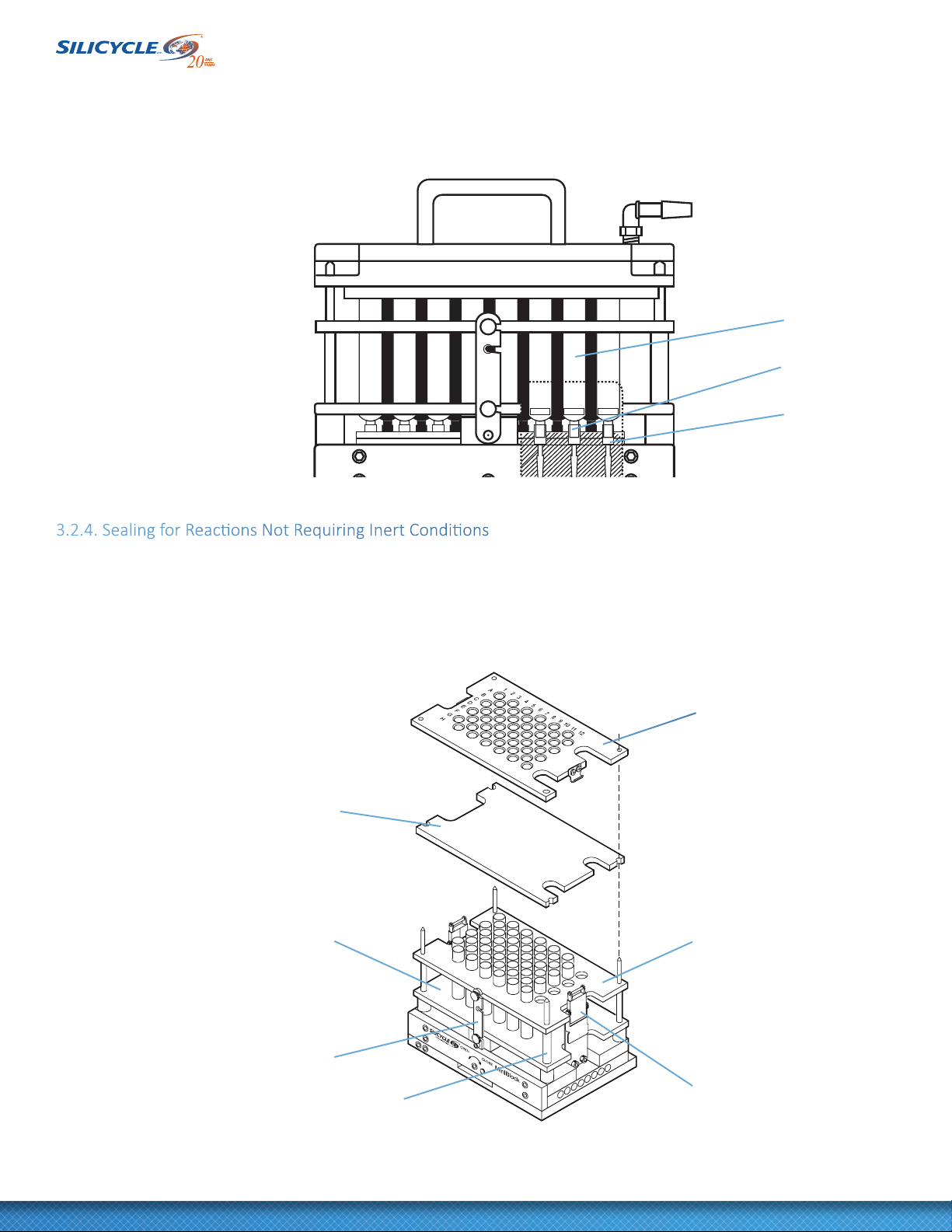
2. Ensure the luer ps of the Reacon Tubes are fully and evenly posioned in the female luer ngs of the Pinch-Tube Inserts (Figure 20).
The luer ngs are compressed together by installaon of the septum and cover plate, or inert atmosphere manifold.
Upper Alignment Plate
Heat Transfer Block
Reacon TubeReacon Tube
Small Alignment Pin
Heat Transfer Block
Lower Alignment Plate
Thumb Screw
Front Locking Arm Large Alignment Pin
Large Alignment Pin
Figure 18: Heat Transfer Block Installed
CAUTION: Take care inserng glass reacon tubes, so the Teon®
heat shrink sleeves are not snagged or damaged.
Figure 19: Insert Reacon Tubes
SiliCycle MiniBlock® User Guide
20 www.SiliCycle.com | inf[email protected]om
Figure 20: Male / Female Luer Fing
3.2.4. Sealing for Reacons Not Requiring Inert Condions
1. Select the appropriate septum for your applicaon (see secon 2.3 SiliCycle MiniBlock System Materials). Mul-layer or laminated septa
should be placed over Reacon Tubes with the Teon® side down and the largest end notch ed to the large alignment pin.
2. Place the appropriately colored cover plate over the Reacon Tubes, being careful to correctly orient the plate
on the large alignment pin (Figure 21).
Reacon Tube
Female Luer Fing
Valve Insert
Spring Clamp
Lower Alignment Plate Upper Alignment Plate
Figure 21: Seang Reacon Vessels
Cover Plate
Septum Layer
Large Alignment Pin
Locking Arm
Table of contents
Popular Laboratory Equipment manuals by other brands


Smeg
Smeg GW0160 Technical manual

Seiler
Seiler Coolscope 985 LED owner's manual

Markes International
Markes International HiSorb Agitator U-HSAG-20 Instructions for use

DDS Calorimeters
DDS Calorimeters CAL3K-F installation guide

Azure Biosystems
Azure Biosystems Cielo AIQ030 user manual

Nikon
Nikon NWL860 Series manual


