Di-soric ID-07 User manual

ID-07 Handheld DPM
Imager
User’s Manual
ID-07 User’s Manual

ii ID-07 Handheld DPM Imager User’s Manual
Copyright and Disclaimer
Copyright ©2010
ISO 9001 Certified
Issued by TüV USA
All rights reserved. The information contained herein is proprietary and is provided solely for the purpose
of allowing customers to operate and/or service di-soric manufactured equipment and is not to be
released, reproduced, or used for any other purpose without written permission of di-soric.
Throughout this manual, trademarked names might be used. Rather than place a trademark (™) symbol
at every occurrence of a trademarked name, we state herein that we are using the names only in an editorial
fashion, and to the benefit of the trademark owner, with no intention of infringement.
Disclaimer
The information and specifications described in this manual are subject to change without notice.
Latest Manual Version
For the latest version of this manual, see the Download Center on our web site at:
www.di-soric.com.
Technical Support
Warranty and Terms of Sale
For Standard Warranty information contact:
di-soric GmbH & Co. KG
Steinbeisstraße 6
DE-73660 Urbach
Fon: +49 (0) 71 81 / 98 79 - 0
Fax: +49 (0) 71 81 / 98 79 - 179
www.di-soric.com

ID-07 Handheld DPM Imager User’s Manual iii
Introduction
Table of Contents
Chapter 1 Quick Start
Check Required Hardware ......................................................................1-2
USB Interface ..........................................................................................1-3
RS-232 Interface......................................................................................1-4
Install di-soric ID ......................................................................................1-5
Select Model ............................................................................................1-6
Select Protocol and Connect to Imager ...................................................1-7
Chapter 2 Using di-soric ID
EZ Mode ..................................................................................................2-2
Application Mode .....................................................................................2-4
Tree Controls ...........................................................................................2-5
Menu Toolbar...........................................................................................2-6
Send/Receive ....................................................................................... 2-16
Chapter 3 Basic Operations
Targeting and Decoding ..........................................................................3-2
Scanning Guidelines................................................................................3-3
Decode Zones and Lighting Zones..........................................................3-4
Illumination System..................................................................................3-7
Illumination Sequence .............................................................................3-9
Chapter 4 Communications
Communications by di-soric ID ................................................................4-2
Communications Overview ......................................................................4-3
USB Interface ..........................................................................................4-4
RS-232 Interface......................................................................................4-5
Preamble .................................................................................................4-7
Postamble................................................................................................4-9
Preamble and Postamble by di-soric ID ................................................4-11
Keyboard Mapping.................................................................................4-12
Text Commands ....................................................................................4-13
Other Communications Settings in di-soric ID .......................................4-14
Chapter 5 Read Cycle
Read Cycle by di-soric ID ........................................................................5-2
Button Stay-Down Time...........................................................................5-3
Ignore Duplicate Symbol Timeout............................................................5-4
Region of Interest ....................................................................................5-5
Chapter 6 Symbologies
Symbologies by di-soric ID ......................................................................6-2
Aztec........................................................................................................6-3
BC412......................................................................................................6-4
Codabar ...................................................................................................6-5
Code 39 ...................................................................................................6-6
Code 93 ...................................................................................................6-7

iv ID-07 Handheld DPM Imager User’s Manual
Table of Contents
Code 128 ................................................................................................. 6-8
Composite ............................................................................................... 6-9
Data Matrix ............................................................................................ 6-10
GS1 DataBar ........................................................................................ 6-11
Interleaved 2 of 5................................................................................... 6-12
MicroPDF417......................................................................................... 6-13
PDF417 ................................................................................................. 6-14
Pharmacode .......................................................................................... 6-15
QR Code............................................................................................... 6-17
UPC/EAN.............................................................................................. 6-18
Symbology Identifier ............................................................................. 6-19
Chapter 7 I/O Parameters
I/O Parameters by di-soric ID .................................................................. 7-2
Operational Feedback ............................................................................. 7-3
Gain Control ............................................................................................ 7-4
Exposure ................................................................................................. 7-5
Data Validation ........................................................................................ 7-6
Chapter 8 Advanced Operations
Dot Peen Enhanced Illumination Settings ............................................... 8-2
Illumination Settings by di-soric ID .......................................................... 8-3
Lock Settings ........................................................................................... 8-6
Chapter 9 Terminal
Terminal View.......................................................................................... 9-2
Find.......................................................................................................... 9-3
Send ........................................................................................................ 9-4
Macros..................................................................................................... 9-5
Terminal Right-Click Menu ...................................................................... 9-6
Terminal Dropdown Menu ....................................................................... 9-7
Chapter 10 Utilities
Device Control ....................................................................................... 10-2
Differences from Default........................................................................ 10-3
Firmware................................................................................................ 10-4
Advanced............................................................................................... 10-6
Appendices
Appendix A General Specifications .........................................................A-2
Appendix B Electrical Specifications .......................................................A-4
Appendix C Default/Reset Procedure......................................................A-7
Appendix D Maintenance ........................................................................A-8
Appendix E Troubleshooting ...................................................................A-9

ID-07 Handheld DPM Imager User’s Manual v
Introduction
About the ID-07 Handheld DPM Imager
The key features of the ID-07 Handheld DPM Imager are:
• Illumination technology
• Best-in-class X-Mode DPM decode algorithms
• Image Enhance optimization for difficult-to-decode direct part marks
• LED targeting pattern
• USB and RS-232 interface options
• Fast processing
• Rugged design
• Sustains 50+ drops from six feet to concrete
About This Manual
This manual provides complete information on setting up, installing, and configuring the
ID-07 Handheld DPM Imager. The chapters are presented in the order in which the imager
would be assembled, configured, and optimized.
Highlighting
Cross-references and web addresses are highlighted in blue bold.
References to di-soric ID, its toolbar headings (Communications, Symbologies, I/O
Parameters, etc.) and menu headings are highlighted in Bold Initial Caps.

vi ID-07 Handheld DPM Imager User’s Manual
Statement of Agency Compliance
Statement of Agency Compliance
The ID-07 has been tested for compliance with FCC regulations and was found to be com-
pliant with all applicable FCC Rules and Regulations.
IMPORTANT NOTE: To comply with FCC RF exposure compliance requirements, this
device must not be co-located or operate in conjunction with any other antenna or transmitter.
CAUTION: Changes or modifications not expressly approved by the party responsible for
compliance could void the user’s authority to operate the equipment.
The ID-07 has been tested for compliance to CE (Conformité Européenne) standards
and
guidelines and was found to conform to applicable CE standards, specifically the EMC
requirements: EN 55024, ESD EN 61000-4-2, Radiated RF Immunity EN 61000-4-3, EFT
EN 61000-4-4, Surge EN 61000-4-5, Conducted RF Immunity EN 61000-4-6, Magnetic
Field Immunity EN 61000-4-8, Voltage Dips EN 61000-4-11, Emissions EN 55022, Class B
Radiated Emissions, and Class B Conducted Emission, Current Harmonic Emissions IEC
61000-3-2, Voltage Fluctuation and Flicker IEC 61000-3-3 Class B.

ID-07 Handheld DPM Imager User’s Manual vii
Introduction
Statement of RoHS Compliance
All di-soric ID readers are RoHS-Compliant.
These products meet all the requirements of the European Parliament and the Council of the
European Union for RoHS compliance. In accordance with the latest requirements, our
RoHS-compliant products and packaging do not contain intentionally added Deca-BDE,
Perfluorooctanes (PFOS) or Perfluorooctanoic Acid (PFOA) compounds above the
maximum trace levels. To view the documents stating these requirements, please visit:
http://eur-lex.europa.eu/LexUriServ/LexUriServ.do?uri=CELEX:32002L0095:EN:HTML
and
http://eur-lex.europa.eu/LexUriServ/LexUriServ.do?uri=OJ:L:2006:372:0032:0034:EN:PDF
Please contact your sales manager for a complete list of di-soric’s RoHS-Compliant
products.
This declaration is based upon information obtained from sources which di-soric believes to be reliable, and from
random sample testing; however, the information is provided without any representation of warranty, expressed or
implied, regarding accuracy or correctness. di-soric does not specifically run any analysis on our raw materials or
end product to measure for these substances.
The information provided in this certification notice is correct to the best of di-soric’s knowledge at the date of
publication. This notice is not to be considered a warranty or quality specification. Users are responsible for
determining the applicability of any RoHS legislation or regulations based on their individual use of the product.

viii ID-07 Handheld DPM Imager User’s Manual
Statement of RoHS Compliance

ID-07 Handheld DPM Imager User’s Manual 1-1
1 Quick Start
Contents
This section is designed to get your ID-07 Handheld DPM Imager up and running quickly
so you can get a sense of its capabilities and test sample symbols. Detailed setup informa-
tion for configuring the imager for your specific application can be obtained in the subse-
quent sections.
Your interface type will determine how data is received by your host. When sending data by
USB, you must open a text editor in your host computer. When sending data serially, you
must use a terminal program such as HyperTerminal or di-soric ID’s Terminal view (RS-232
only).
Check Required Hardware ........................................................................................................... 1-2
USB Interface ............................................................................................................................... 1-3
RS-232 Interface .......................................................................................................................... 1-4
Install di-soric ID........................................................................................................................... 1-5
Select Model................................................................................................................................. 1-6
Select Protocol and Connect to Imager........................................................................................ 1-7

1-2 ID-07 Handheld DPM Imager User’s Manual
Check Required Hardware
Check Required Hardware
Parts List for USB ID-07:
• One ID-07 Handheld DPM Imager
• One 12 ft. USB cable (pre-attached to imager)
Parts List for RS-232 ID-07:
• One ID-07 Handheld DPM Imager
• Cable clip attachment
• Spacer
• Two threaded screws
• RS-232 Interface Kit
– 8 ft. coiled R-232 cable
– Power supply (U.S. or Euro)

Quick Start
ID-07 Handheld DPM Imager User’s Manual 1-3
USB Interface
Note: The USB interface draws its power from the host.
USB Configuration
Installation Steps for USB
1. Connect the USB cable to the host.
2. Open any program in your host computer
that can receive keyboard text, such as
Notepad.
3. Read the Reset to USB Factory
Defaults symbol below:
4. Read the Save Settings symbol.
Item Description Part Number
1ID-07 Handheld DPM Imager ID-07-IM3-2-US
2USB Cable Included
USB Configuration
Reset to USB
Factory Defaults
Save
Settings
Test Symbol
(ABCDEFGHIJKLMNOP)
1-4 ID-07 Handheld DPM Imager User’s Manual
RS-232 Interface
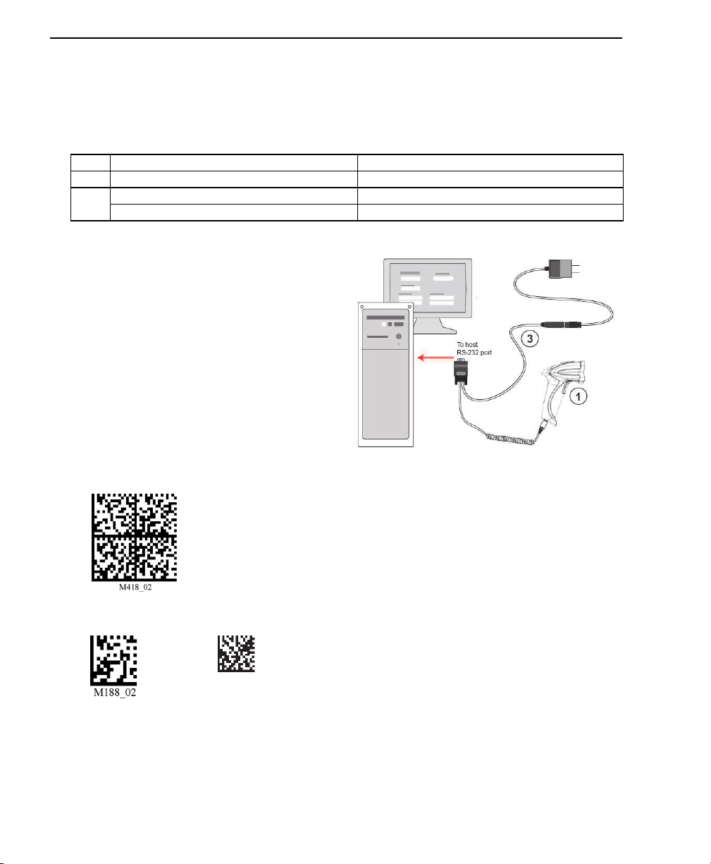
RS-232 Interface
Note: Unlike USB, the RS-232 interface does not draw its power from the host computer.
RS-232 Configuration
Installation Steps for RS-232
1. Power-off the host.
2. Connect the 8-pin mini-DIN on the
cable to the ID-07.
3. Connect the 9-pin D-sub connector to
the host computer’s serial port.
4. Connect the cable to the power supply.
5.
Plug in the power supply and power-on
the host.
6. Start up a terminal program (such as
di-soric ID’s Terminal view or Hyper-
Terminal)
and set to 57.6K baud, 8
data bits, none parity, and 2stop bits.
7. Read the Reset to RS-232 Factory
Defaults symbol below.
8. Read the Save Settings symbol.
Item Description Part Number
1ID-07 Handheld DPM Imager ID-07-IM3-2-US
3RS-232 Interface Kit (USA) ID-PS-S-115V-2.5-KIT
RS-232 Interface Kit (Europe) ID-PS-S-230V-2.5-KIT
RS-232 Configuration
Reset to RS-232
Factory Defaults
Save
Settings
Test Symbol
(ABCDEFGHIJKLMNOP)
Quick Start
ID-07 Handheld DPM Imager User’s Manual 1-5
Install di-soric ID
di-soric ID Software can be found on the di-soric Tools USB Stick that is packaged with the ID-
07.
1. Follow the prompts to install di-soric ID from the USB Stick.
2. Click on the di-soric ID icon to run the program.
Note:
di-soric ID can also be installed from the Download Center at www.di-soric.com.
di-soric ID System Requirements
• 166 MHz Pentium processor (Pentium II processor recommended)
• Windows Vista, XP, or 2000 operating system
• Internet Explorer 5.0 or higher
• 64 MB minimum RAM (128+ MB RAM recommended)
• 80 MB hard drive space
• 800 x 600 minimum 256 color display (1024 x 768 32-bit color recommended)
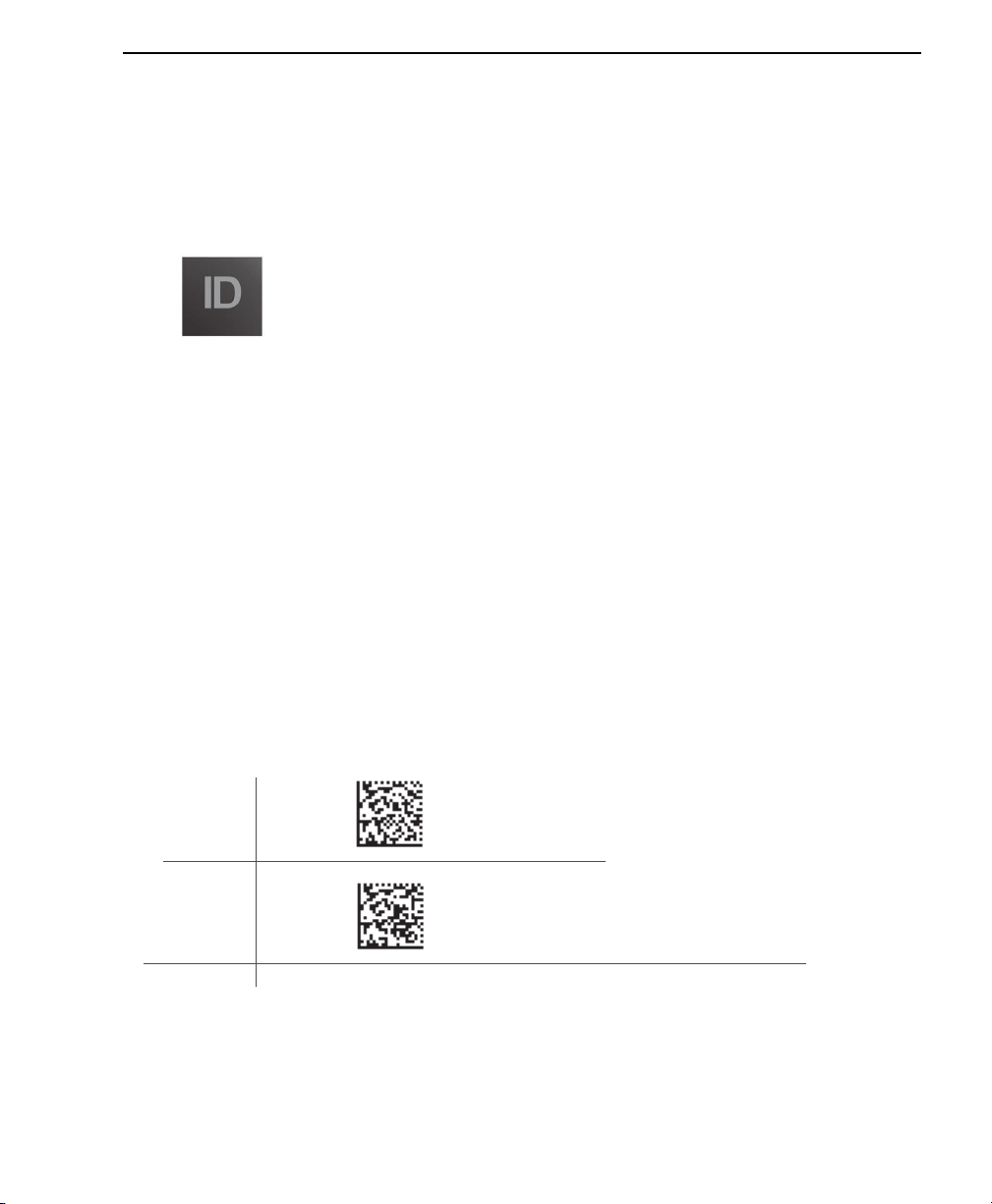
Important: The imager must be in one of the modes below to communicate with di-soric
ID. Read the symbol below that corresponds with your communication interface, and then
read the Save Settings symbol.
USB
Connect
Mode
RS-232
Connect
Mode
USB
RS-232

1-6 ID-07 Handheld DPM Imager User’s Manual
Install di-soric ID
Save
Settings
Quick Start
ID-07 Handheld DPM Imager User’s Manual 1-7
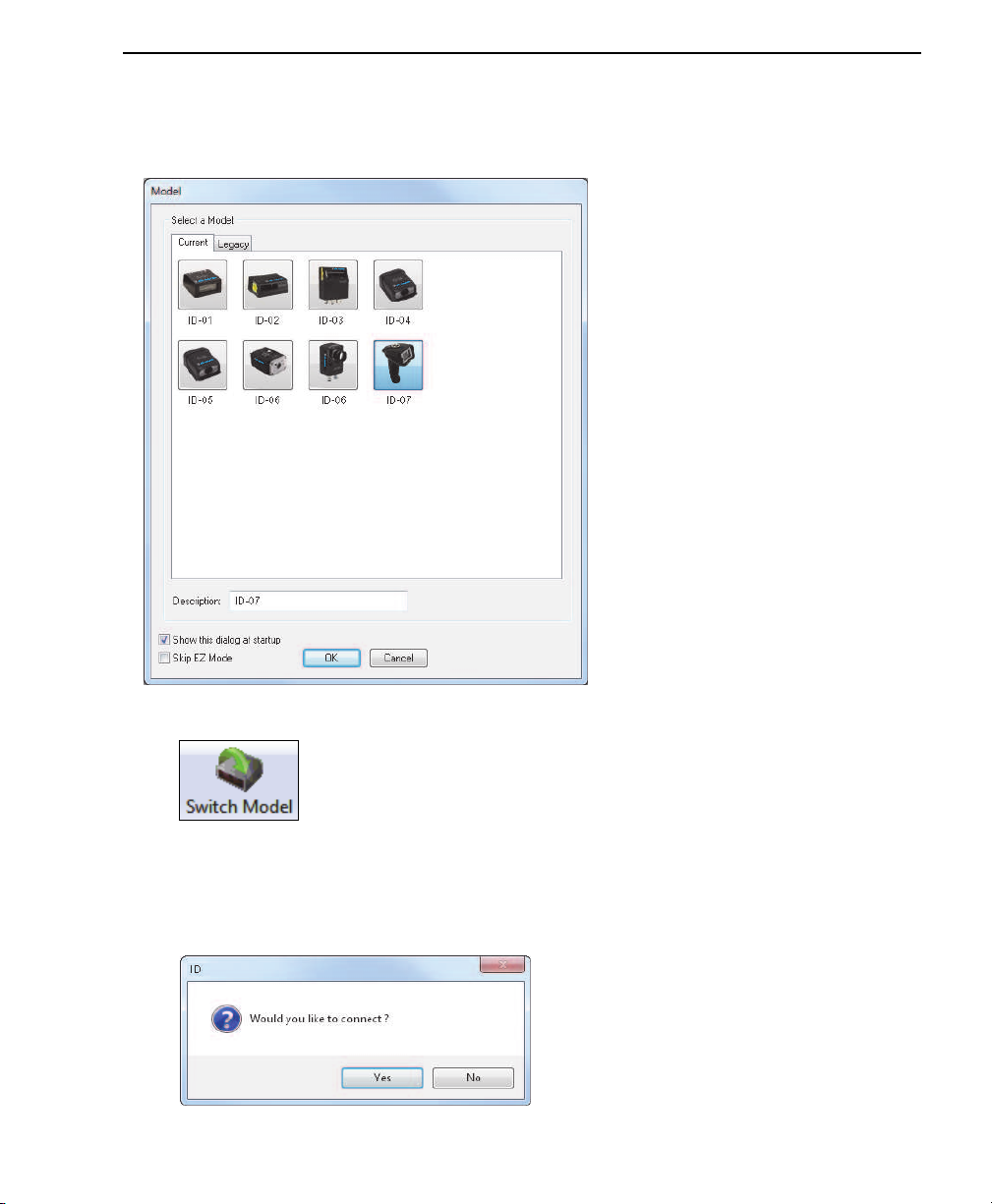
Select Model
When you start di-soric ID, the following menu will appear:
If you need to select another model later, click Switch Model at the top of the screen.
1. Click the ID-07 button and then click OK. If you do not want to make this selection
every time you start di-soric ID, uncheck “Show this dialog at startup”.
2. Select the default reader name (ID-07-1), or type a name of your choice in the
Description text field and click OK.
3. Click Yes when this dialog appears:
1-8 ID-07 Handheld DPM Imager User’s Manual
Select Protocol and Connect to Imager
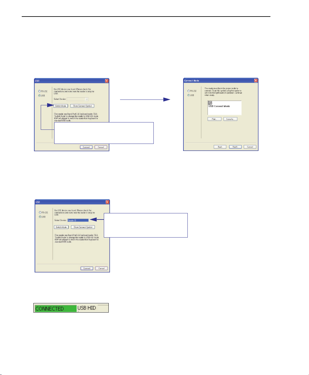
Select Protocol and Connect to Imager
USB (Standard)
• In the Select Protocol dialog box, select the communications protocol you are using
and click Next.
• Print the USB Connect Mode symbol (also shown in the Install di-soric ID step) and
decode it with the imager to ensure that you are in the correct communications mode.
Keep the printed symbol in a convenient place for future use.
• Click Next when you are finished.
The USB Select Device dialog will then reappear:
• You will see a “Reader ID” number in the USB Select Device field. Click Connect.
• When you are connected successfully, the CONNECTED message will appear in a
green box in the status bar at the bottom right of the screen.
You are now ready to configure your imager using di-soric ID. Subsequent sections pro-
vide more detailed information about di-soric ID’s configuration options.
From the default USB settings, click the
Switch Mode button to connect to the
reader in USB HID Mode.
Reader ID number should match
the serial number on the base of
the imager.

Quick Start
ID-07 Handheld DPM Imager User’s Manual 1-9
RS-232 Option
• Select RS-232 and click the Show Connect Symbol button.
• Print the RS-232 Connect Mode symbol (also shown in the Install di-soric ID step) and
decode it to ensure that you are in the correct communications mode. Keep the printed
symbol in a convenient place for future use.
• Click Next to return to the RS-232 dialog.
• Configure RS-232 settings and COM port and click Connect
.
• When you are connected successfully, the CONNECTED message will appear in a
green box in the status bar at the bottom right of the screen.
If the connection attempt fails, enable a different communications port, check your port
connections, and try again.
You are now ready to configure your imager using di-soric ID. Subsequent sections pro-
vide more detailed information about di-soric ID’s configuration options.

1-10 ID-07 Handheld DPM Imager User’s Manual
Select Protocol and Connect to Imager

ID-07 Handheld DPM Imager User’s Manual 2-1
2Using di-soric ID
This section is designed to help you understand the structure and application of di-soric
ID.
When you open di-soric ID, unless otherwise specified in the di-soric ID Preferences dia-
log accessible from the Options heading on the menu toolbar, you will enter EZ Mode for
initial setup. From there, you can enter Application Mode (App Mode) and access several
configuration menus (Communications, Read Cycle, Symbologies, I/O Parameters, a
Terminal interface, and a Utilities interface).
di-soric ID can be used to configure the ID-07 Handheld Imager in the following ways:
•Tree Controls: Each configuration menu contains a list of all option settings that pertain
to that specific element of imager operation. For example, the Communications menu
shows a Communications Mode command, and then the options RS-232 Serial, USB
Keyboard, and USB Native (HID), all of which are accessible from a dropdown menu.
•Graphic User Interfaces: Settings can be configured using such point-and-click tools
as radio buttons, tabs, spin boxes, check boxes, and drag-and-drop functions.
•Terminal: di-soric ID’s Terminal interface allows you to send configuration and utility com-
mands directly to the imager by typing them in the provided text field.
EZ Mode....................................................................................................................................... 2-2
Application Mode.......................................................................................................................... 2-4
Tree Controls................................................................................................................................ 2-5
Menu Toolbar ............................................................................................................................... 2-6
Send/Receive ............................................................................................................................ 2-16
2-2 ID-07 Handheld DPM Imager User’s Manual
EZ Mode
EZ Mode
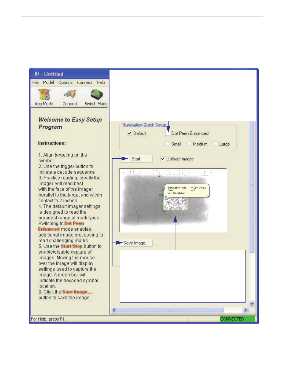
The EZ Mode screen is the first thing you will see when you start di-soric ID. EZ Mode
will help you get your imager up and running quickly, and will acquaint you with the di-
soric ID interface.
Click Start to upload the most recent image
acquired before releasing the trigger. When an
image is captured, it is displayed here. Click Save
Image to save it to a location of your choice. Good
read images show a green border around the symbol.
If you hover your cursor over the symbol, you will
see the illumination, gain, and resolution settings
that were used in capturing the image. Symbol data
is displayed in the area under the Save Image button.
The purpose of Dot Peen Enhanced in Illumination Quick Setup
is to optimize settings for typical dot peen marks. Dot Peen
Enhanced causes the imager to run a two step illumination
sequence (Low Angle and then Red Dome) and matches the
morphological operator (Grow Dark and Grow Light) to the
expected dot peen response. The size of the morphological
operator is selectable (Small, Medium, or Large). These settings
can also be controlled by programming symbols (see Dot Peen
Enhanced Illumination Settings).
Table of contents
Other Di-soric Laboratory Equipment manuals


