SILION SLR1218 User manual
Desktop Reader Writer Hardware Manual
1
Desktop UHF RFID reader/writer
Hardware manual
(For SLR1218、SLR5218、SLR5318)
Edition:V1.0
Date:2020/1/17
Beijing Xinlianchuangzhan Electronic Technology Co., Ltd
Tel:(+86)010-62153842/62153840
http://www.silion.com.cn

Desktop Reader Writer Hardware Manual
2
Disclaimers
This document does not grant any license of intellectual property
rights, and does not grant any license of intellectual property righ
ts, express or implied, or by prohibiting speech or other means. Exce
pt for the responsibilities stated in the terms and conditions of sal
es of its products, our company does not assume any other responsibil
ities. In addition, our company does not make any express or implied
warranty on the sale and/or use of this product, including the applic
ability of the product for a specific purpose, marketability, or liab
ility for infringement of any patent, copyright or other intellectual
property rights. The company may modify the product specifications a
nd product descriptions at any time without notice.

Desktop Reader Writer Hardware Manual
3
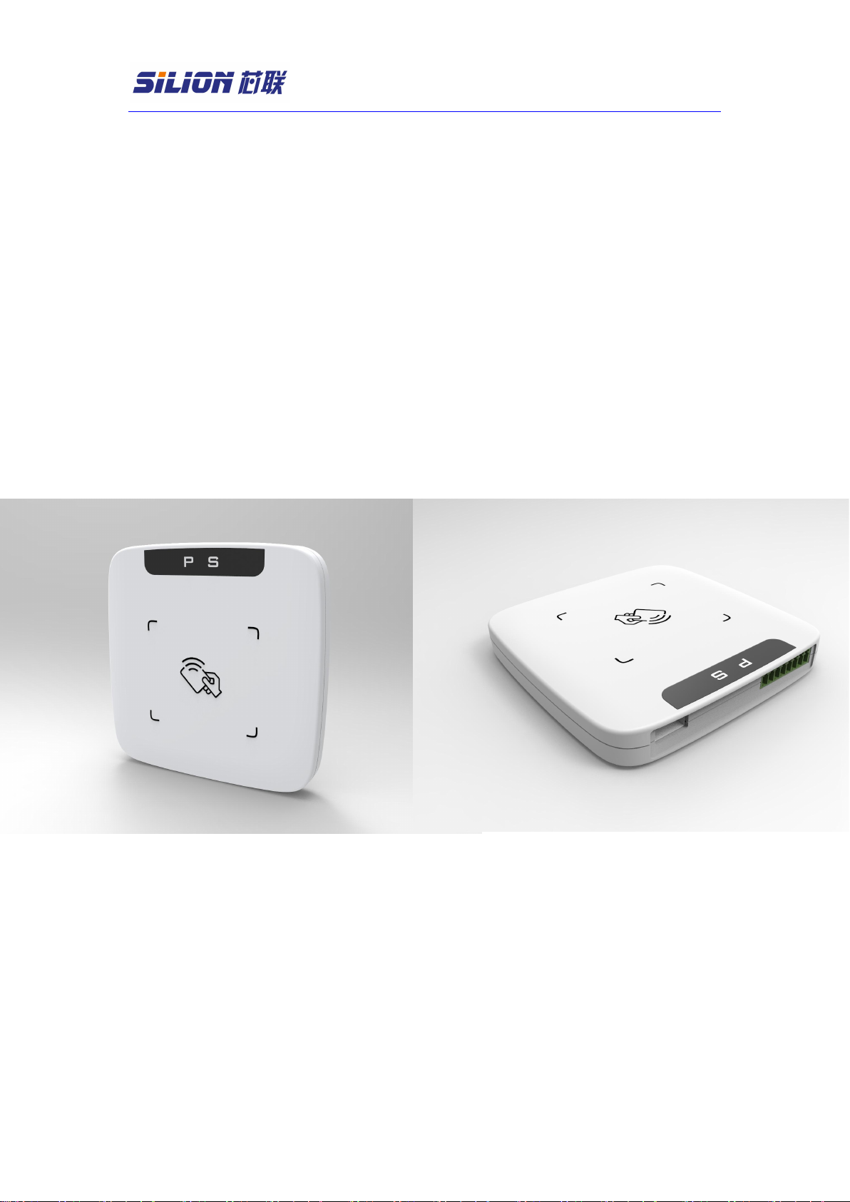
Chapter 1 Overview
This series of readers have built-in small gain PCB antenna, excellent structural
design, can effectively prevent the tag from being misread or serial read, positioned in
the use of close reading card scenarios. Suitable for supply chain management, asset
management and other fields of card issuing applications and close card reading
applications. At the same time, it can support the optional high-gain ceramic antenna,
combined with the high-performance RFID module to meet the use of higher card
reading performance scenarios.
The series currently has three main products
model
model difference
SLR1218
Power range 5 - 30dbm,high-performance
SLR5318
Power range 5 - 30dbm
SLR5218
Power range 13 - 20dbm
Chapter 2: Technical Parameters
Label / transfer protocol
Tagged agreement
EPC Class 1 Gen 2(ISO18000-6C)
Radio frequency interface
Antenna connection
Default 0 dBi round polarized PCB antenna, optional
2 dBi round polarized ceramic antenna
Output power range
SLR1218: 5dBM~30dBm Adjustment accuracy:1dBm
SLR5318: 5dBM~30dBm Adjustment accuracy:1dBm
SLR5218:13dBM~20dBm Adjustment accuracy:1dBm
Receiving sensitivity
SLR1218: < -85dBm
SLR5318:< -75dBm
SLR5218:< -65dBm
Work area support
FCC(NA,SA)902-928MHz
ETSI(EU) 865-867MHz
SRRC-MII(P.R.China)840-845 MHz、920-925MHz
OPEN'(Custom)840-960MHz
Transmission control interface
communication
interface
USB2.0 communication / RS232 serial port communication, portport
rate: 115200 bps (default)
Universal GPIO port
Two sets of inputs, and two sets of outputs
Work status tips
Power indicator, read card status indicator, buzzer
format
physical dimension
110mm×110mm×16.5mm
Power supply / power consumption
DC power supply
USB power supply, external 5V (+ / -0.25V) power supply

Desktop Reader Writer Hardware Manual
4
power dissipation
Work: (separate USB supply, only maximum transmitting
power of 27 dBm)SLR1218: 3.9W(27dBm)/4.8W(30dBm)
SLR5318: 2.7W(27dBm)/3.6W(30dBm)
SLR5218: 1.0W (20dBm)
Stand:
SLR1218:0.35W
SLR5318:0.25W
SLR5218:0.25W
environmental character istics
working temperature
-10℃ - +55℃
Storage temperature
-20℃ - +60℃
function
Label reading rate
SLR1218 :> 100 tag/second
SLR5318 :> 50 tag/second
SLR5218 :> 50 tag/second
(In special case, related to labeling performance)
Read the card distance
0dBi PCB Antenna 2 dBi Ceramic Antenna
SLR1218 :5cm - 80cm SLR1218 :20cm - 3.0m
SLR5318 :3cm - 60cm SLR5318 :10cm - 2.5m
SLR5218 :10cm - 30cm SLR5218 :60cm - 1.0m
The write distance is about 50% of the read
distance(Test label: ALIEN9662 white card)
Chapter 3: Hardware Description
3.1 Interface description

Desktop Reader Writer Hardware Manual
5

Desktop Reader Writer Hardware Manual
6
USB:USB 1.1 / USB 2.0
GPIO:(Universal Input / Output interface), from left to right (Pin
1-Pin 8)
pin
Definition
instruction
1
+5V
The equipment is connected to 5V(+/-0.25V) power supply
2
GND
Power supply of equipment
3
TXD
RS232 serial port data output
4
RXD
RS232 Serial port data entry
5
IN1
GPIO Input (5-12V)
6
IN2
GPIO Input (5-12V)
7
OUT1
GPIO output (5V)
8
OUT2
GPIO output (5V)
USB port / RS232 serial port communication switching switch::
switch
1
2
3
USB
ON
OFF
OFF
RS232
OFF
ON
OFF
(P)Indicator light: power supply indicator light, always on the power
on.
(S)Indicator: Read the card indicator until the card is on.

Desktop Reader Writer Hardware Manual
7
3.4 Appearance size
(unit:mm)
Desktop Reader Writer Hardware Manual
8
第4章Direction for use
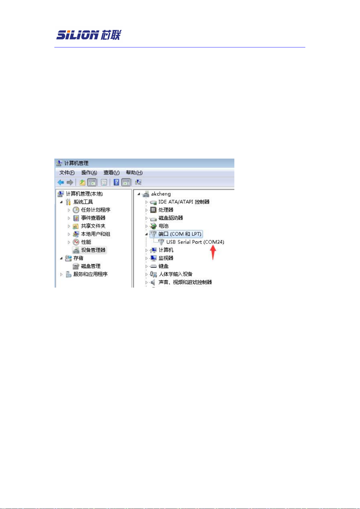
4.1 link
Connect the device through a serial port cable or USB cable to power up
the device, (desktop right-click computer-Management-Device
Manager-view the available COM slogan). Connection setting: fill in the
COM slogan for the address, and select a single antenna for the number
of antenna ports. Please refer to the demonstration software instructions
for specific functions.

Desktop Reader Writer Hardware Manual
9
4.2 GPIO control
Description: demonstrate the software-reader parameter GPIO interface setting
IN1 (GPI1)
Input status: High level (5-12V) software determination logic 0
Input status: Low level (0V, or suspended) software determination logic 1
IN2 (GPI2)
Input status: High level (5-12V) software determination logic 0
Input status: Low level (0V, or suspended) software determination logic 1
OUT1(GPO1)
Software control logic of 0 Output end: Low level (0V)
Software control logic of 1 Output end: High level (5V)
OUT2(GPO2)
Software control logic of 0 Output end: Low level(0V)
Software control logic of 1 Output end: High level (5V)
Read card
The GPO 1 logic is in 0 White light / buzzer silent; GPO 1 logic 1

Desktop Reader Writer Hardware Manual
10
indicator lamp
(white) /
Buzzer control
(GPO 1)
,White light goes on / buzzer goes off
Read card
indicator lamp
(red) (GPO 2)
GPO2 logic 0 ,Red light out;GPO2 logic 1 ,The red light is on.
FCC Warning
This device complies with part 15 of the FCC Rules. Operation is subject to the following two
conditions: (1) This device may not cause harmful interference, and (2) this device must accept
any interference received, including interference that may cause undesired operation.
Any Changes or modifications not expressly approved by the party responsible for compliance
could void the user's authority to operate the equipment.
Note: This equipment has been tested and found to comply with the limits for a Class B digital
device, pursuant to part 15 of the FCC Rules. These limits are designed to provide reasonable
protection against harmful interference in a residential installation. This equipment generates uses
and can radiate radio frequency energy and, if not installed and used in accordance with the
instructions, may cause harmful interference to radio communications. However, there is no
guarantee that interference will not occur in a particular installation. If this equipment does cause
harmful interference to radio or television reception, which can be determined by turning the
equipment off and on, the user is encouraged to try to correct the interference by one or more of
the following measures:
-Reorient or relocate the receiving antenna.
-Increase the separation between the equipment and receiver.
-Connect the equipment into an outlet on a circuit different from that to which the receiver is
connected.
-Consult the dealer or an experienced radio/TV technician for help.
This equipment complies with FCC radiation exposure limits set forth for an uncontrolled
environment. This equipment should be installed and operated with minimum distance 20cm
between the radiator & your body.
This manual suits for next models
2
Table of contents


