3. MOUNTING AND CONNECTION.
READER OPERATION
Internal Indication Control:
External Indication Control:
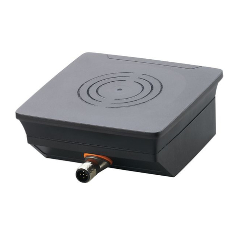
The reader is mounted on a flat surface which allows to easily approach it with tokens.
Please mount at ambient air temperature 5°C and above.
To mount the CP-Z 2MF Surface reader, perform the following operations:
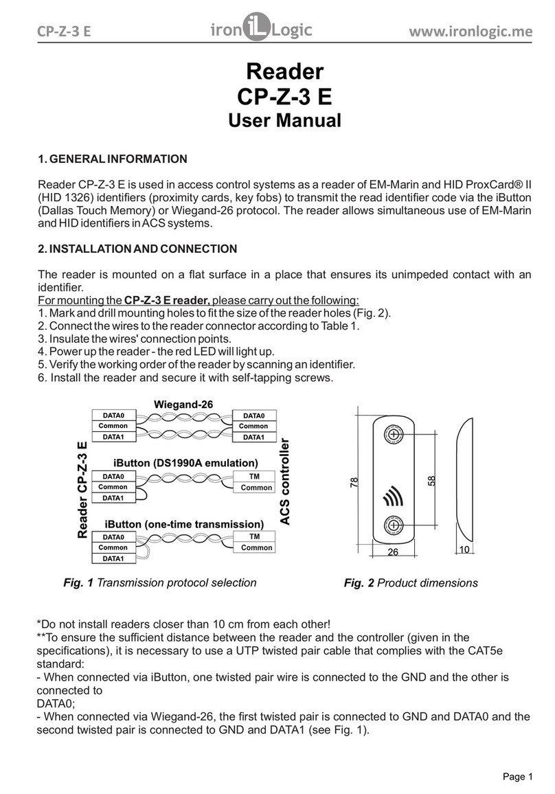
- Connect wires to the reader per Figures 2 and 3. When power is properly connected,
the red LED will light up.
Insulate the wires junctions.
When ready, the red LED is lit, indicating that reader is properly powered.
When a Mifare token is brought into reader working zone, its UID is read, and for Modes 2 and
3, also authorisation and reading additional codes from the token memory are performed. If the
read operation was successful, it will be indicated by the LED shortly going dark.
At this moment the transmission occurs: in Modes 1 and 2, of the acquired UID, and in Mode 3
of the acquired protected memory sector. The data are transmitted to the controller via iButton
(Dallas Touch Memory), Wiegand-26 or Wiegand-34 protocol. (as chosen during the
configuration).
The configuration is performed by free M3NConf.zip software.
The reader has both internal and external indication control.
- The red LED is always on while no token is present in the reader working zone.
- On a token entering the working zone, the red LED is going off.
- While the token stays in the working zone, the red LED stays off.
- For Modes 2 and 3, when an uninitialized token is approached to the reader, the red LED
momentarily turns off and then goes back on.
- While the uninitialized token stays in the working zone, the red LED stays on.
- Done by a controller via external control terminal RED, or RS-485 commands.
- Activated when an external control signal from the controller is detected.
Note: For Modes 2 and 3, when reading an uninitialized token, the red LED is momentarily
going off and then back on.
Proximity
RFID
-
-
4.
- Mark and drill a 20 mm hole. Insert the reader into the hole, and secure it from the rear with a
mounting ring nu.t
To operate at the top of the specified line distance to controller, please use a UTP cable CAT5e.
page 2
black
yellow
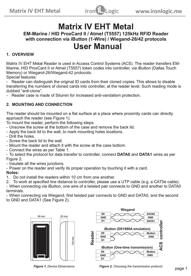
Figure 3. The wires purpose.
GND
D1
+12V
red
D0
ACS Controller
Reader
Figure 2. Choosing the transmission protocol.
iButton (One-time transmission)
iButton (DS1990A emulation)
CP-Z 2MF www.ironlogic.me
GND
D0
Common
iButton
D1
GND Common
D1
D0
Wiegand
DATA1
iButton
GND
D0
Common
DATA0
D1
green
RED
white
