SILLA DB 3000 Installation and operation manual

GB Operating, maintenance manual
Macchine Edili e Stradali s.r.l.
Via S,Gimignano n°96 Poggibonsi (SI) –Italy
REL. 04 Date Juli 11, 2018

TRUCK MIXER DB 3000/4000/4500 HYDROSTATIC GB
User Manual Rel. 4 of 11/07/18 Page 2 of 20
INDEX
Page
7.5.6
Indicators dev.
14
7.5.7
Headlights/Horn switch
14
7.5.8
Accelerator pedal
14
7.5.9
Brake pedal
14
7.5.10
Parking brake lever
14
7.5.11
Direction reversing lever
14
7.5.12
Drum lifting lever
15
7.5.13
Shovel arms drive lever
15
7.5.14
Grab bucket drive lever
15
7.5.15
Water pump lever
15
7.5.16
Drum rotation lever
15
7.5.17
Driver’s seat rotation
15
7.6
Use of the machine
15
7.6.1
Starting the engine
15
7.6.2
Stopping the engine
15
7.6.3
Starting the mixer
15
7.6.4
Auto-loader
16
7.6.5
Water system
16
7.6.6
In action on the construction site
16
8
MAINTENANCE
16
8.1
Routine and extraordinary maintenance
16
8.1.2
Daily maintenance
16
8.1.3
Weekly maintenance
16
8.1.4
Maintenance to be performed every 15 days
16
8.1.5
Maintenance to be performed every 100 hours
17
8.1.6
Maintenance to be performed every 2000 hours
17
8.2
Corrective maintenance
17
8.2.1
Troubleshooting
17
8.3
Maintenance of hydraulic system
18
8.3.1
Check the brake pedal
18
8.3.2
Check the parking brake
18
8.3.3
Check the tires
18
8.3.4
Spare parts
18
9
DISMANTLING
18
9.1
Disassembling and dismantling
18
9.2
Disposal
18
11
WARRANTY REGISTRATION FORM
19
1. INTRODUCTION This manual is directed at the user and operator who will be responsible for the
safe, efficient and trouble free operation of the machine. Read and understand this manual and always follow the safety
precautions stated in the chapters General Precautions and Operation. Keep this manual handy for frequent reference and to
pass on to new operators or owners. The machine is equipped with tested special safety devices and safety systems. SILLA
cannot be held responsible for unauthorized modifications or procedures, replacements and/or all other modifications changing
the use the machine has been designed and manufactured for.
Warranty: The mechanical and electrical products of the machine, which are not normal service items, have a one-year
warranty starting from the date of the sale. The warranty does not cover the normal service items like tools, driving belts, liquids
and oils. The defective or not properly working products will be replaced by the Technical Personnel of the Manufacturer of the
machine, after the defective product has been proven to be defective. The warranty does not cover the products in case of
modification, abuse, misuse, improper use, negligence or improper maintenance (routine and extraordinary maintenance) as
shown by this I.M. This warranty is valid in the territory of the European Community. The consumer is the right holder according
to the applicable national laws governing the sale of consumables and this warranty makes those rights unprejudiced.
2. MARKING A label with the following machine identification data is installed on the machine:
- Name and address of the manufacturer and/or legal representative in Europe; - Machine type; - Serial or part number; - Year
of construction; - Weight of the machine. - Max. rating; - Ready mixed product in litres; - Loading capacity.
For assistance and information or spare parts SILLA Macchine Edili e Stradali
refer to: Via S.Gimignano , 96
53036 –POGGIBONSI (SI) - ITALY
Tel. ++39-0577 - 938051 Fax. ++39-0577 –981609
E-mail: info@sillaitaly.com Web Site: www.sillaitaly.com
This Instruction Manual and all the enclosed documents are freehold property of the Company SILLA.
INDEX
Page
1
INTRODUCTION
2
2
MARKING
2
3
GENERAL PRECAUTIONS
3
4
CHARACTERISTICS
3
4.1
Description of the machine
3
4.2
Dimensions and technical
characteristics
4
4.3
Safety instructions
4
5
INSTALLATION/NEW SITE
5
5.1
Transport
5
5.2
Placing and how to leave the
machine
5
5.3
Areas of respect and overall dimens.
5
5.4
Preparations before use
6
5.5
Safety first
6
5.6
Putting into operation
6
5.7
Training
6
6
ADJUSTMENTS
6
6.1
Adjusting the machine
6
6.2
Adjusting the parking brake
6
6.3
Adjusting the seat
6
7
CONTROL INSTRUMENTS
7
7.1
Warning lights
7
7.2
Controls
7
7.3
Water system
8
7.4
Electrical and hydraulic diagrams
8
7.4.1
Relay/fuse box
8
7.4.2
Gear case wiring
9
7.4.3
Column wiring
10
7.4.4
Service junction box
11
7.4.5
Separate facility for oil coolers
12
7.4.6
Hydraulic diagram
13
7.5
Operation and controls
14
7.5.1
Steering wheel
14
7.5.2
Starting switch
14
7.5.3
Hour meter
14
7.5.4
Rotary lamp switch
14
7.5.5
Warning lights switch
14

TRUCK MIXER DB 3000/4000/4500 HYDROSTATIC GB
User Manual Rel. 4 of 11/07/18 Page 3 of 20
Reproduction (in any form or way inclusive recording and photocopy) in whole and/or part is forbidden without
the written authorisation of the Company SILLA. In case this Instruction Manual should get lost or destroyed ask the
Company SILLA for a complete copy.
Caution! Precautions and instructions to be strictly followed.
3. GENERAL PRECAUTIONS
The operating safety of the machine is only granted for the functions listed in this instruction manual.
SILLA cannot accept any responsibility, if the machine should be used for different uses than those listed in this
manual or those, which do not comply with the operating instructions.
SILLA cannot accept any responsibility for safety, liability and performances of the machine, if the precautions and the
instructions of this instruction manual, especially referred to: use, in the construction site and on the road (only for homologated
vehicles), maintenance and dismantling are disregarded.
The operating safety is only guaranteed for the functions listed in this instruction manual.
SILLA cannot accept any responsibility, if the machine is used for other purposes than those stated in this manual and which
do not comply with the operating instructions.
For all repairs, please refer to the After-Sales Service authorised by the supplier of the machine. The user of the machine is the
only responsible for its good and safe operation, if the machine was not repaired or maintained by the specialized or authorised
personnel.
For special maintenance and repairs use only original spare parts.
All these operations must be performed in a suitable location, with the machine turned OFF, taking care to remove the ignition
key from the panel in order to avoid inappropriate starting (by other peopled) and with the parking brake applied.
All the operators using the machine shall be trained on its correct use, the warning devices, the behaviour and actions to
maintain for the proper use of the machine, assuring either their personal or other’s safety.
The machine is delivered with by the operator himself. Check and maintain these protection devices and the machine
according to the maintenance schedule. The operator shall be cautious in using the machine when the drum and the bucket
are moving and when approaching with his hands, and particularly:
DO NEVER TURN ON THE MACHINE WITHOUT THE PROTECTION SHIELDS;
DO NEVER REMOVE AND NEVER OPEN THE PROTECTION SHIELDS WHILE THE MACHINE IS RUNNING.
Ensure good lightening in the work area and around the machine, in order to avoid shady areas, dangerous dazzling and
stroboscopic effects.
Before starting any work, check the work area for any unauthorised persons or obstacles.
The operator shall wear appropriate clothing: work gloves, protective helmet, safety shoes, and respiratory protection. Do not
wear any jewellery or clothing that can get caught or distract from the operation of the machine.
Follow the safety instructions, in particular: Turn off the machine before opening or cleaning it; ensure no one can turn it on by
accident; Use the protective equipment (work gloves, ear muffs, safety shoes, respiratory protection) during use, assembly and
maintenance of the machine;
Be cautious in approaching all the moving parts. - Before starting work and turning on the machine, CHECK: - the work area (5
metres all around the machine) for any persons or obstacles.
Follow the safety instructions shown in chapter SAFETY PRECAUTIONS.
4. CHARACTERISTICS
4.1 Description of the machine The truck mixers for the construction sites are designed,
manufactured, tested and sold by the company Silla. These machines are designed for loading aggregate,
mixing and transporting the concrete on construction sites.
The main feature of these machines is that they are very simple, strong and reliable. The peculiarity of the
articulated frame and the permanent four-wheel drive allow it to operate on all types of terrains ensuring safety and reliability
over time. The auto-loading arm with the grab bucket and the mixing drum, make the machine reliable. A quick check in the
morning will give you a faithful and safe fellow worker all day. The driver’s seat allows excellent visibility in any position, and the
operator has full control of the controls and of the central diagnostic panel.
TRUCK MIXER DB 3000/4000/4500 HYDROSTATIC GB
User Manual Rel. 4 of 11/07/18 Page 4 of 20
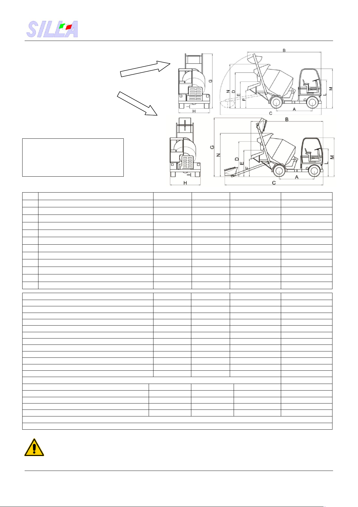
4.2 Overall dimensions:
GRAB SYSTEM
SHOVEL
WARNING |
Approximate measurements,
In particularly those in height,
may vary depending on
wheel mounted.
DIMENSIONS
DB 3000
DB 4000
DB 4500
DB 4500
A
AXLE SPACING
2700mm
2700mm
2700mm
2720mm
B
MINIMUM LENGTH
5300mm
5300mm
5300mm
5500mm
C
MAX. LENGTH (With bucket on the ground)
7150mm
7150mm
7150mm
7800mm
D
HOPPER HEIGHT
2600mm
2600mm
2580mm
2580mm
E
CONVEYOR HEIGHT
2000mm
2000mm
19800mm
2100mm
F
MAX. UNLOADING HEIGHT
1620mm
1620mm
1617mm
1617mm
G
MAXIMUM HEIGHT
3200mm
3750mm
3750mm
4100mm
H
MAXIMUM WIDTH
2270mm
2270mm
2420mm
2420mm
I
MIN. HEIGHT FROM THE GROUND
320mm
320mm
320mm
320mm
L
STEERING WHEEL HEIGHT
2520mm
2520mm
2520mm
2600mm
M
CABIN WHEL
3000mm
3000mm
3050mm
3050mm
M
MAXIMUM HEIGHT HOPPER
3015mm
3015mm
3020mm
3020mm
TECHNICAL CHARACTERISTICS
DB 3000
DB 4000
DB 4500
DB 4500
DRUM CAPACITY
3000Lt
4000Lt
4500Lt
4500Lt
MIX CAPACITY
2400Lt
3000Lt
3500Lt
3500Lt
GRAB BUCKET CAPACITY
270Lt
270Lt
270Lt
500Lt
WATER RESERVOIR CAPACITY
650Lt
650Lt
650Lt
650Lt
UNLADEN WEIGHT
5600Kg
6000Kg
6450Kg
MAXIMUM LOAD
5500Kg
6500Kg
7700Kg
7700Kg
DRIVE
Hydrostatic
Hydrostatic
Hydrostatic
Idrostatica
FORWARD/REVERSE SPEED
2/2
2/2
2/2
2/2
MAXIMUM SPEED
25 Km/h
25 Km/h
25 Km/h
25 Km/h
GRADEABILITY AT FULL LOAD
30%
30%
30%
30%
BRAKES
Disc brakes
Disc brakes
Disc brakes
Freni a disco
TYRES
12,5/80-18
12,5/80-18
405/70 R20”14PR
405/70 R20”14PR
MOTOR
DB 3000
DB 4000
DB 4500
DB 4500
MAX. ENGINE POWER
HP102
HP102
HP102
HP102
NUMBER OF CYLINDERS
4
4
4
4
COOLING SYSTEM
Water
Water
Water
Water
FUEL TANK CAPACITY
55Lt
55Lt
55Lt
55Lt
OPTIONAL
LOADING SYSTEM WITH SHOVEL, HALF CAB, CLOSED CAB, AGGREGATE SCALE
4.3 SAFETY INSTRUCTIONS Limits for use, space, life. The machine has been designed and
built for use on open-air construction sites, according to the climate conditions with reference to the previous para.
(4.2). The machine must never be used in underground excavations, in areas at risk for explosions or fires, in closed
places. The machine is designed and built for transporting concrete, sand, pebble gravel, cement, and water and for use on
Attention !!!! Concrete dosed at
350 kg/m3(plastic consistency S2)
concrete volume can vary according
to the local granulate, grain size,
porosity and percentage and humidity
of sand.

TRUCK MIXER DB 3000/4000/4500 HYDROSTATIC GB
User Manual Rel. 4 of 11/07/18 Page 5 of 20
construction sites only. Ensure the areas of respect of the machine according to the range and the working areas involved. The
machine has an attachment for towing. It’s absolutely necessary for the proper performance of the machine and the security
that the towing weight of 1500kg is not exceeded. Otherwise SILLA is not responsible for any damage that may be caused.
Never carry passengers. The machine is designed and built to carry only the operator / driver.
Working on hilly terrain can be dangerous.
Always operate in the low gears, do not move downhill with the engine off or with the transmission in neutral.
In condition of darkness pay attention to the work area and help yourself with all the lighting devices at your disposal.
It can be dangerous to leave the machine unattended in public places; place barriers around the work area, to keep away
unskilled people.
In case of maintenance, the raised arms of the bucket may fall suddenly; install a safety arm before working under the same.
Diesel fuel is flammable.
Before connecting or disconnecting an electrical component, be sure to be familiar with the electrical system. An incorrect
connection may cause injury and damage.
A battery with frozen electrolyte can explode if used or charged. Do not use the machine with frozen battery and do not
recharge it. To prevent freezing, keep the battery fully charged.
The battery electrolyte is toxic and corrosive. Do not inhale gases from the battery. Keep the electrolyte away from clothing,
skin, mouth and eyes. Wear safety goggles.
The machine is grounded to the negative pole of the battery.
Always ground the negative terminal of the battery. When connecting the battery the ground cable (-) must be connected last.
When disconnecting the battery the ground cable (-) must be disconnected first.
Always remember that the oil is a special waste and shall be disposed of according to the terms of
the law.
CAUTION!!!!!! EVERY USE OF THE MACHINE DIFFERENT THAN THOSE STATED BY THE MANUFACTURER
IN THIS INSTRUCTION MANUAL IS AN IMPROPER USE. THEREFORE, THE COMPANY SILLA CANNOT ACCEPT ANY
RESPONSIBILITY, IF THE MACHINE SHOULD BE USED BY THE OPERATOR FOR DIFFERENT USES THAN THOSE
LISTED IN THIS INSTRUCTION MANUAL OR THOSE NOT COMPLYING WITH THE OPERATING INSTRUCTIONS.
5. INSTALLATION/NEW CONSTRUCTION SITE
5.1 Transport Caution!! The truck mixers are shipped with two wheels off, to unload them from
the container, provide a plane at the same level as the Container, otherwise the machine may be
damaged. The top or cab are disassembled, so you just have to mount them, connect the flashing lamp with
the special connector, turn the battery cut-off switch to the ON position (because it was set to OFF during
transport) and refuel.
The strength of the machines, their shape and size, are such to ensure transport and storage safely and without damage. The
weight of the machines is shown on the CE plate; the weight being relevant, be very careful when loading and unloading. Make
sure that the vehicle, which transports the truck mixer and the loading ramps, has adequate size and capacity. Always stop the
wheels of the truck with wedges before loading or unloading the truck mixer.
Fix the ramps to the truck and drive the truck mixer on it with due caution. Switch off the engine, remove the ignition key, pull
the parking brake and insert the battery cut-off switch. Remove the ramps, fix the wheels of the truck mixer with wedges, and
tie the machine to the means of transport. The truck mixer has no specific points of anchorage; therefore tie the frame with
straps. The machine is delivered with the following accessories:
- 1 Manual for use, maintenance and spare parts; - 1 Instruction manual of Engine Manufacturer;
- 1 Hand pump equipped for greasing; - 1 Socket wrench for wheel assembly;
It is recommended to take all precautions during loading-unloading and transport, in order to avoid danger
and damage to people and machine. The loading and transport devices must be designed and approved in
accordance to the weight to be supported. Never lift the machine, it is too dangerous.
Follow the safety instructions shown in chapter SAFETY PRECAUTIONS.
5.2 Placing and how to leave the machine The machine must be placed / parked in a flat area
of the construction site, where it can be: Covered –Washed –Stored –Upket.
Provide in the area of placement of the machine: -Power supply; -Lighting;
-Water supply. - Ensure an area of respect around the machine of at least 2 meters.
The machine must be placed in areas without gas, explosive materials and/or highly flammable materials.
Follow the safety instructions shown in chapter SAFETY PRECAUTIONS.
The use of the machine by unauthorized personnel is not allowed.
5.3 Areas of respect and dimensions The working space needed for correct use and proper
maintenance is at least 5 metres, that is the area of respect around the machine, within which you must pay close
attention to both people and things, thus avoiding obstacles while using the machine.
Working debris may make the driver’s seat slippery. Use personal protective equipment such as safety shoes
and provide periodic cleaning of the floor.
Warning: the use of chemicals, shampoos or products to clean the machine can be harmful to a person’s

TRUCK MIXER DB 3000/4000/4500 HYDROSTATIC GB
User Manual Rel. 4 of 11/07/18 Page 6 of 20
health. Carefully read the instructions of the product used. They can also modify the quality of the painting of the truck
mixer and damage its hydraulic parts, then use carefully.
5.4 Preparations before use. Use protective gloves when preparing and putting into use.
Check levels of engine oil, clutch and brake fluid, hydraulic oil. Check refuelling so as to avoid having to stop work.
Check tire pressure and their condition of use.
Clean shoes and steps from mud and grease before getting on the machine. Be sure of perfect visibility from the driver’s seat
and that the warning labels and the various accident prevention devices are clearly visible. Wear ear protections.
5.5 Safety first. All machines can be dangerous. When a truck mixer is properly used and maintained, it is an
extremely safe machine.
If the machine is used incorrectly, it can be rather dangerous. Both in this manual and on the machine you will find the
warnings, indicating all the potential dangers and how to avoid them. If you have any doubts, ask your dealer or your direct
manager for explanations. Do not work with the machine until you are able to control it. Do not start any work until you are
certain of your and other’s safety. You may run into accidents if you perform unfamiliar operations without prior testing, which
must be carried out in free areas, away from other people and on level ground.
Follow the safety instructions shown in chapter 4.3 SAFETY PRECAUTIONS.
5.6 Putting into operation Before putting the machine into operation, especially the very first time, or
when it is installed on a new work place, carry out the following preliminary checks and keep in mind the following
technical warnings and tips: -Check oil level;
-Check tire pressure and condition of use; - Check the area of respect and the workspaces;
-Check that the protections are set correctly; -Check that the indications and warning signs are placed on the
machine and are easily visible. -Carry out a general test of all mechanical and electrical controls of the machine, so
as to check their accuracy, efficiency and operation; - Check levels of engine oil, clutch and brake fluid, and hydraulic fluid; -
Check refuelling so as to avoid having to stop work.
5.7 Training Before using the machine, read carefully this instruction manual and understand how
to use the machine in a safe way.
6. ADJUSTMENTS
6.1 Adjusting the machine At first operation on the construction site, the machine does not need any
adjustments. Verify only the points defined in: 5.4 Preparations before use.
Never carry out adjustments with the machine running/operating. Follow the safety instructions shown in
chapter SAFETY PRECAUTIONS. Every single adjustment and/or modification of the safety/work parameters
set on the machine, which has not been authorised by the technical personnel of the company SILLA or
which is not stated in this instruction manual, may influence the quality of the product and injure the operator’s health.
The company SILLA declines any responsibility for liability, performances and safety of the machine in case of
modification/alteration of the machine and of the relevant operation/safety parameters.
6.2 Adjusting the parking brake
Brake adjustment is carried out directly on the brake lever. By turning the knob of the brake lever you can adjust by loosing or
tightening. To get a proper adjustment, the stress on the brake lever must be of 10Kg.
Avoid “playing” with the brake knob, you may modify it and when necessary it will not work properly.
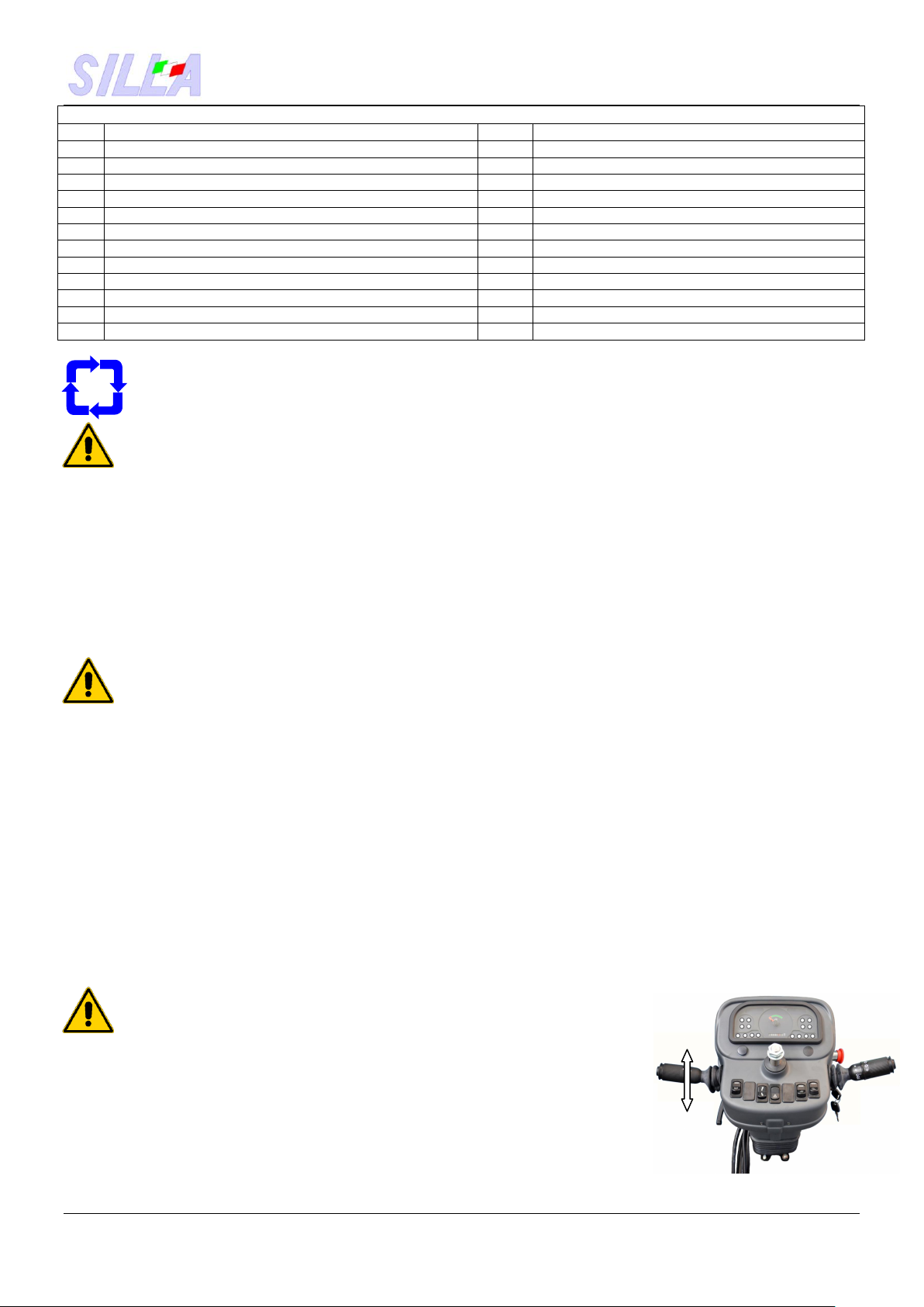
6.3 Adjusting the seat Forward-backward adjustment.
The seat can be moved back and forth to adjust the distance of the pedals: the
operator must be able to press the pedals while keeping his back resting
against the seat. To adjust the seat position, act on the indicated lever and slide
the seat in the ideal position.
Make sure that the seat is locked.

TRUCK MIXER DB 3000/4000/4500 HYDROSTATIC GB
User Manual Rel. 4 of 11/07/18 Page 7 of 20
7. CONTROL INSTRUMENTS
7.1 Warning lights 1 2 3 9 10 11 12
1- Belt broken 4 17
2- Low on fuel
3- Hydraulic oil level 5 13
4- Hydraulic contamination filter
5- Air filter 6 14
6- Generator charge
7- Motor oil
8- Water indicator 715
9- Hydraulic oil cooling fan 8 16
10-------------------------
11-Fast running 18
12-Slow running
13-Main headlights
14-Glow plugs preheating
15-Direction indicator lamps
16-Parking
17-Fuel level
18-Hour meter
7.2 Controls
19-Slow/fast running + Forward Reverse
20-Headlights
21-Rotary lamp
22-Working light
23-Ignition switch
24- Commutator switching steering wheel
control to drive position
A/R 25-Warning lights
27 26-Working light
19 20 27- Emergency stop
29
28
21
22 23
24
25 31 26
28------------------------
29- Klaxon
30-Acoustic signal: water temperature,
belt broken and engine heads temperature
31-Negative brake (parking)
30
TRUCK MIXER DB 3000/4000/4500 HYDROSTATIC GB
User Manual Rel. 4 of 11/07/18 Page 8 of 20
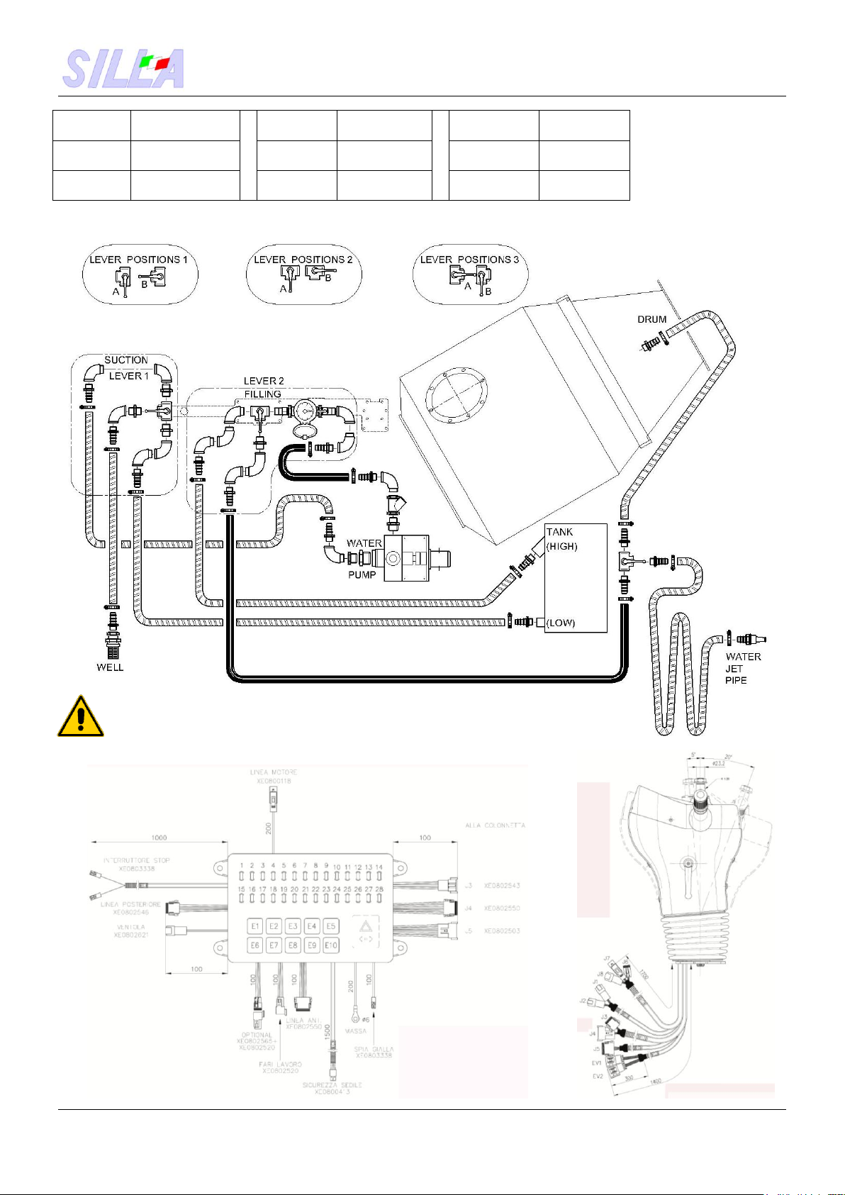
7.3 Water system
On first use you have to
fill the tank: lever 1 in
position “A”
lever 2 in position “A”.
When the tank is full: lever 1 in position “B”, lever 2 in position “B”, lever 3 in position “B”if you want to put water in the drum,
lever 3 in position “A”if you want to wash with the water jet pipe.
Follow while using the system the safety instructions shown
in chapter SAFETY PRECAUTIONS.
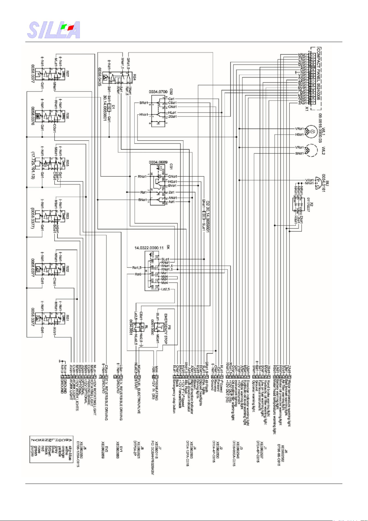
7.4 Electrical and hydraulic diagrams
7.4.1 Relay/fuse box
Lever 1
Position
Function
Lever 2
Position
Function
Lever 3
Position
Function
A
Suction from the
well
A
Flow to the
tank
A
Water jet
pipe
B
Suction from the
tank
B
Flow to the
drum
B
Drum

TRUCK MIXER DB 3000/4000/4500 HYDROSTATIC GB
User Manual Rel. 4 of 11/07/18 Page 9 of 20
7.4.2 Gear case wiring
TRUCK MIXER DB 3000/4000/4500 HYDROSTATIC GB
User Manual Rel. 4 of 11/07/18 Page 10 of 20
7.4.3 Column wiring
TRUCK MIXER DB 3000/4000/4500 HYDROSTATIC GB
User Manual Rel. 4 of 11/07/18 Page 11 of 20
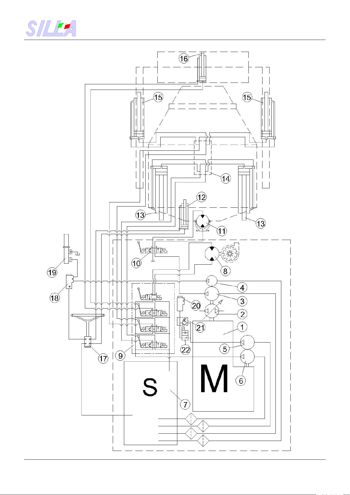
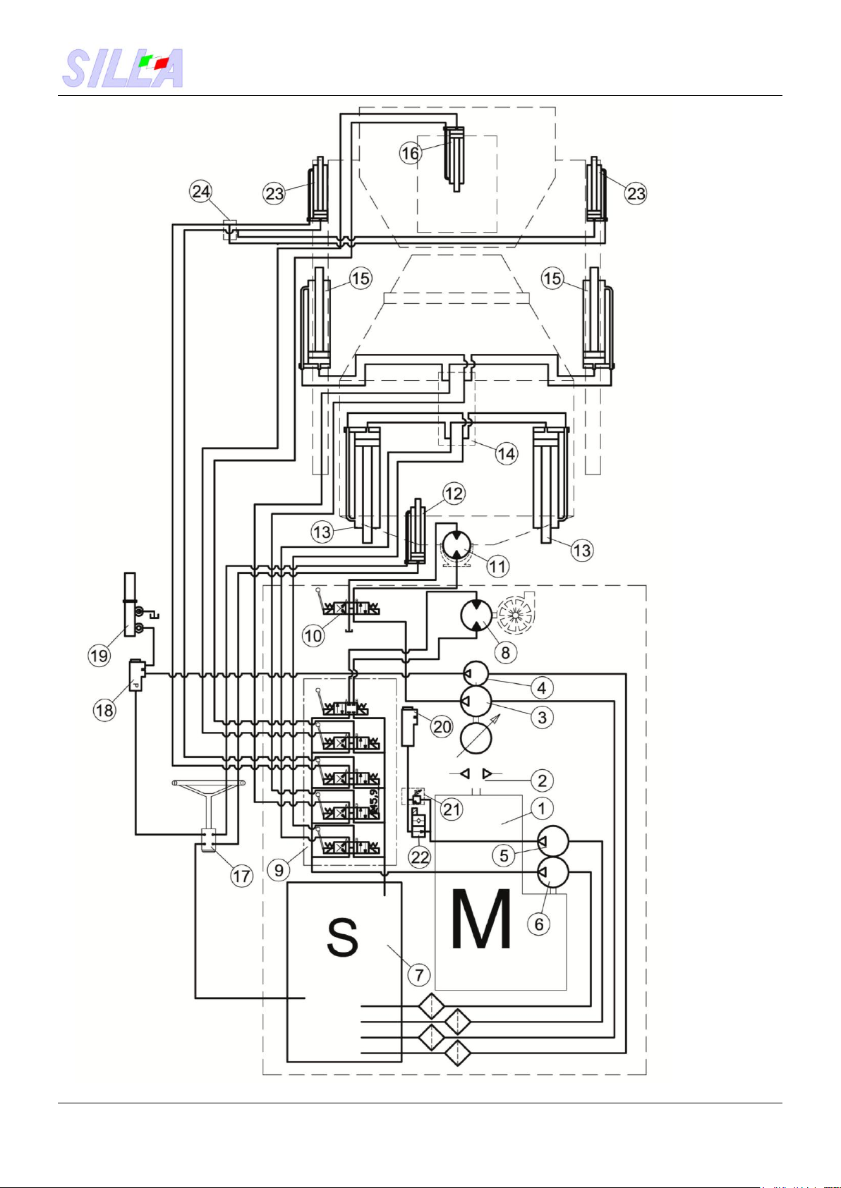
7.4.6 Hydraulic scheme Grab system version
TRUCK MIXER DB 3000/4000/4500 HYDROSTATIC GB
User Manual Rel. 4 of 11/07/18 Page 12 of 20
7.4.7 Hydraulic scheme Shovel version
TRUCK MIXER DB 3000/4000/4500 HYDROSTATIC GB
User Manual Rel. 4 of 11/07/18 Page 13 of 20
LEGEND - HYDRAULIC DIAGRAM
Item
Description
Item
Description
1
Diesel engine
13
Hydraulic cylinders (drum lifting)
2
Hydrostatic pump
14
Distribution block
3
Gear pump (drum)
15
Hydraulic cylinders (arm)
4
Gear pump (hydr. steering gear/servo brake)
16
Hydraulic cylinder (grab bucket)
5
Gear pump (Brake release)
17
Hydraulic steering gear
6
Gear pump (facilities)
18
Brake pump
7
Oil tank
19
Servo brake
8
Hydraulic motor (water pump)
20
Brake pump
9
Distributor (facilities)
21
Valve
10
Distributor (drum rotation)
22
Solenoid valve (brake release)
11
Hydraulic motor (drum geared motor)
23
12
Hydraulic cylinder (hydr. steering gear)
24
7.5 Operation and controls
7.5.1 Steering wheel
Turn the steering wheel in the desired direction. Power-assisted steering system powered by means of hydraulic
pump and acting with hydraulic jack on the front half-frame.
All duties are hydraulic: transmission, steering, braking and all movements, therefore: Do not use the
machine with the engine off !!!!
7.5.2 Starting switch
Position “0” OFF engine stop: Engine stop position.
Before stopping the machine, make sure that it is stopped and the parking brake set.
Position “I”ON.In this position the switch connects the battery to all the electric circuits with the exception of the headlights
and the warning lights. The lights and the emergency circuit are always live. The ignition key automatically returns to that
position when it is released from the position “II” and “III”.
Position “II” Preheating.
When starting the machine in cold climates, keep the key in this position to heat the glow pugs. The preheating position should
not be maintained for more than 15 seconds.
Position “III”Starting. Activates the engine starter and the engine runs.
Do not activate the engine starter for more than 20 seconds at a time. After each starting attempt, let cool for
at least 2 minutes then repeat the operations from position “II”. Do not use the starter with voltages greater
than 14Volt.
Do not use the starter to move the vehicle.
7.5.3 Hour meter Indicates the working hours of the machine with the key inserted, check it to
determine the lubrication and maintenance program.
7.5.4 Rotation lamp switch Enables/Disables rotating lamp.
7.5.5 Warning lights switch Enables/Disables warning lights.
7.5.6 Indicators device Activates the direction indicators.
7.5.7 Headlights/Horn switch Activates the headlights, low beams at first click and high beams at the second
click. By pressing it in any position (zero, first click or second click) it activates the klaxon.
7.5.8 Accelerator pedal Press the accelerator pedal to increase the motor speed, release it to decrease.
Use the accelerator pedal with the upmost attention. It’s not a racing car!!!
7.5.9 Brake pedal Press the brake pedal to slow down or stop the vehicle.
The service brake acts hydraulically by means of pump on the brakes.
The stop lights must light up when the brakes are used.
Use the machine only if both stop lights are working properly.
7.5.10 Parking brake lever To set the parking brake, pull the lever upwards. To release push it downwards.
Operate the lever to set the parking brake whenever you leave the driver’s seat.
Never start with the parking brake set.
7.5.11 Direction reversing lever Used to reverse the direction of travel of the machine.
Use it only when the machine stops and at a speed
as low as possible.

TRUCK MIXER DB 3000/4000/4500 HYDROSTATIC GB
User Manual Rel. 4 of 11/07/18 Page 14 of 20
Grab system controls
7.5.12 Drum lifting lever
Push forward to lift the drum, pull to reposition.
7.5.13 Grab bucket arms drive lever
Push to lower the arms, pull to lift.
7.5.14 Grab bucket drive lever
Push to open the bucket, pull to close it.
7.5.15 Water pump lever
Pushing the lever it starts the water pump that stays
in place until switching off by pulling the lever.
(see diagram 7.3 Water system).
7.5.16 Drum rotation lever
Pushing the lever the drum turns in the “discharge”
direction, pulling the lever the drum turns in the “mixing”
direction.
Shovel commands
7.5.17 Drum lifting lever
Push forward to lift the drum, pull to reposition.
7.5.18 Grab bucket arms drive lever
Push to lower the arms, pull to lift.
7.5.19 Door shovel operate lever.
Push to lower, pull to lift up.

TRUCK MIXER DB 3000/4000/4500 HYDROSTATIC GB
User Manual Rel. 4 of 11/07/18 Page 15 of 20
7.5.20 Open/Close lever.
Push to open, Pull to close.
7.5.21 Water pump operate lever.
Pulling yhe lever, operating the water pump.
Push the lever for stop..
7.5.22 Drum rotation lever.
Pushing the lever the drum turms in the “discharge”
Direction, pulling the lever the drum turns in the
“mixing” direction.
ALL THE MAINTENANCE OPERATIONS AND CHECKS MUST
BE CARRIED OUT WITH THE MACHINE TURNED OFF, PARKING BRAKE SET.
Always keep the machine switched off when it is not in use.
Always perform a test of all the controls and check that everything works properly .
Make sure that in the area of respect and work there are no people or objects
large enough to compromise the security.
7.5.17 Driver’s seat rotation The driver’s seat is turned in the direction of work, in order to
check the drum operations, the arms and the grab bucket, by using the lever under
the seat. When pushing it downwards and turning the driver’s seat by hand up to the
180° click, you get the position you want, but be careful when using button n. 24 “driving
switch”, press it whenever you change the direction of the driver’s seat, otherwise the
steering will work in reverse. Repeat the same operations for driving the vehicle on the site.
7.6 Use of the machine
7.6.1 Starting the engine - Make sure that the parking brake is set. -
Check the level of oil in the pan. –Make sure that there is sufficient fuel in the tank for
the work to be performed - Check level of hydraulic oil -Accelerate to about 3/4 of
the run and engage the starter
Caution! When the engine is running do not disconnect the contacts of the
battery, to avoid burning of the capacitor. B A
SPEED VARIATOR:
SLOW (Lever in direction of the snail symbol)
CENTRAL POSITION = NEUTRAL
FAST (Lever in direction of the hare symbol)
To change the speed move the “A” lever in
the desired position (low speed symbol snail)-(fast speed symbol hare). Never change
the speed with machine in movement. The speed variation must always be with
machine stopped and passing from the central neutral position, giving small shots to
the accelerator “B” that facilities the sliding of the lever. Do not force only on the lever
without acting also on the accelerator.
7.6.2 Stopping the engine Reset the throttle control by hand. Activate the stopping device.
7.6.3 Starting the mixer For mixing, the drum seen from the driver’s seat, must rotate counter-clockwise.
- When you want to unload, stop the mixing operation, lift the drum and start clockwise rotation of the drum;
- The starting operations and reverse rotation of the drum must be performed with the engine idling.
CAUTION! At the end of each working cycle, wash the inside of the drum entering a shovelful of gravel, in order to avoid the
formation of incrustations of concrete.
7.6.4 Auto-loader -Open the grab bucket, place the bucket on the heap with the machine stopped, close the bucket and
lift the arms to unload the material inside the hopper.
- Move the machine only when the bucket is lifted from the ground

TRUCK MIXER DB 3000/4000/4500 HYDROSTATIC GB
User Manual Rel. 4 of 11/07/18 Page 16 of 20
7.6.5 Water system -When there is danger of frost, drain all water from the system, including the pump
-For the various manoeuvres see “Operating scheme - water system” (7.3) -Do not run the water pump dry.
The machine is the exclusive responsibility of the operator, which is the only one authorized to manoeuvre it.
Special precautions: Do not carry people;Do not turn the drum with hardened concrete;
Do not drive with the drum raised or with the seat turned towards the drum; Do not abruptly reverse the direction of
rotation of the drum; Do not lower the shovel when the extension is inserted; Do not insist on the control levers when their
cylinders have attained the end of the stroke; Do not abruptly brake or swerve at high speed; Do not tolerate the presence of
others within the range of the machine;
7.6.6 In action on the construction site. Lift the drum (for unloading) only on firm level ground.
On sloping terrain, do not place the machine next to the slope and do not unload in that position, because you are likely to tip
over. Maintain, on steep slopes, the opening of the full-loaded drum always facing upstream. Start the inversion of the rotation
of the drum only with the engine idling. Every time you leave always leave the machine safely, that is with the bucket on the
ground, the drum lowered, the motor stopped and the ignition key removed, the handbrake set. Drive always with the drum
behind the driver’s seat.
SAFETY STANDARDS The driver of public works vehicles, in order to work profitably and safely, must have experience of
mechanical means, know the various commands, the operational characteristics as well as the stability of the machine
entrusted to him and possess an adequate sense of prudence and skill. A risky manoeuvre, out of laziness or to save a few
minutes, could also result in a serious accident with subsequent stopping of the whole construction site.
Never tow the truck mixer on the road. Use appropriate means of transport.
8. MAINTENANCE The machine does not require any particular maintenance work.
The technical solutions and the components installed on the machine reduce the maintenance works at the
minimum. However, we recommend to carry out a series of operations, which aim at ensuring safety, liability
and efficiency of the machine for a long period of time.
During maintenance Work on the machine only after having placed/parked it in the area defined in point 5.2
Placing and how to leave the machine. In the event of mechanical or electrical problems, contact the authorized
personnel. If the machine is out of service due to equipment failure, maintenance or repair, place a special sign to
highlight this status and remove the ignition key.
Always use personal protective equipment during repair and replacement of the machine parts.
Electrical work must be performer only by authorized personnel.
Works on the engine must be performed only by authorized and skilled personnel.
Do not place hands, arms or body parts near the handling and transmission area. Use a suitable device to remove debris
(brush, wooden piece, etc.): never use your hands!
Regular maintenance of the mechanical and electrical machine parts extends the live of the machine, ensures best
performances and is an important safety factor.
8.1 Routine and extraordinary maintenance In the run-in period (50 hours).
Do not force the engine and avoid intensely exploiting the machine performances.
Clean the hydraulic oil drain filter after the first 20 hours.
Check for leaks of hydraulic oil, brake oil, clutch oil, lubricants of various mechanical assemblies. Check tightness of all the
bolts, in particular the fixing of the wheel rims, after the first 20 hours.
Change the motor oil and perform the other operations provided by the manufacturer (see motor instruction booklet provided in
the annex to this manual).
Perform all daily, weekly, fortnightly and successive maintenance operations, a listed below.
8.1.2Daily maintenance at the end of the work Eliminate any anomaly that had occurred.
Thoroughly clean the inside of the drum in order to avoid the formation of incrustations. With a strong jet of water wash the
outside of the machine, to remove any residue. Grease all lubrication points, with the engine stopped and the drum in home
position. Carefully check the tire condition. Check the condition of the brakes. Remove any debris from the driver’s
seat.
DO NOT wash with high pressure jets electrical parts and control elements.
8.1.3Weekly maintenance
Check the oil level of the brakes, clutch oil, hydraulic oil with the engine stopped and the booms down.
Always remember that the oil is a special waste and must be disposed of in accordance with the law.
Check the fluid level of the battery. Check the belt tension of the blower fan.
Wash the engine air filter and fill the pan up to level with oil. Check the condition of the drive belts.
8.1.4Maintenance to be performed every 15 days Check free travel of the brake pedal, normal value is 20/25mm.
Check the travel of the handbrake lever, it must block with an effort not less than 10Kg.
Clean the hydraulic oil drain filter and the tank breather cap.
8.1.5Maintenance to be performed every 100 hours of work
Replace the motor oil, see the instructions of the manufacturer. Replace the fuel filter cartridge.
Replace the suction filter cartridges inside the hydraulic oil tank.
8.1.6Maintenance to be performed every 2000 hours of work Replace the two suction filter cartridges inside the tank.
Replace hydraulic oil after cleaning the magnetic drain plug. Replace the oil exhaust filter.
Always remember that the oil is a special waste and must be disposed of in accordance with the law.

TRUCK MIXER DB 3000/4000/4500 HYDROSTATIC GB
User Manual Rel. 4 of 11/07/18 Page 17 of 20
8.2 Corrective maintenance Other corrective maintenance operations (extraordinary/repairs) must be
performed by authorized service personnel.
8.2.1 Troubleshooting
PART
PROBLEM
CAUSE
Clutch
Does not disengage
Screw on release lever has to be adjusted
Lack or loss of oil in the control device
Slips during engagement
Pump or control cylinder hardened
Hydraulic brake
Insufficient
Lack or insufficient oil
Air bubbles in the circuit
Brake pump with worn seals
Hose which swells under pressure
Worn brake discs
They jam
Pump or cylinders jammed
Handbrake
Insufficient
Hand lever has to be adjusted
Control linkage has to be adjusted
Worn brake discs
Hydr. steering gear
Steering wheel is hardened
Pressure relief valve has to be adjusted
Suction filter cartridge is clogged
Low oil level
Oil leaks or air bubbles in the circuit
Obstructions in the suction pipe
Worn pump
Drum
Rotates slowly if full
Pressure relief valve has to be adjusted
Suction filter cartridge is clogged
Low oil level
Obstructions in the suction pipe
Worn pump
Rotates unevenly
Pressure relief valve has to be adjusted
Suction filter cartridge is clogged
Low oil level
Obstructions in the suction pipe
Worn pump
Concrete is hardening, if drum full
Heavy internal fouling, if drum empty
Autoloader
Rises jerky or with difficulty
Pressure relief valve has to be adjusted
Suction filter cartridge is clogged
Low oil level
Obstructions in the suction pipe
Worn pump
Bucket
Closes without force
Pressure relief valve has to be adjusted
Suction filter cartridge is clogged
Low oil level
Obstructions in the suction pipe
Worn pump
Hydraulic oil
Overheats
Unsuitable oil quality
Low oil level
Pressure relief valves jammed
Worn pumps
Automatic return failure of distributor levers
Excessive insistence on the levers by the operator, with the
cylinders already at the stroke end
Water system
Does not pump water
Suction strainer clogged
Entrained air in the suction pipe
For all other kinds of troubles, please refer to the After-Sales Dept. of the Company SILLA.
CAUTION !!!!! SILLA decline any responsibility in case the machine does not undergo maintenance as
prescribed in this instruction manual and in case of use of spare parts and accessories other than original
and not appropriate.

TRUCK MIXER DB 3000/4000/4500 HYDROSTATIC GB
User Manual Rel. 4 of 11/07/18 Page 18 of 20
8.3 Maintenance of hydraulic system
Protected against dust and infiltration, no special maintenance is required, unless verification of the level, but it requires a
thorough cleaning of the oil. If you have to replace the two filter cartridges inside the tank, you need to drain the oil and remove
the cover. Use only clean containers and fill the oil through funnel fitted with a filter. Any other work on the system must only be
performed by qualified personnel and with appropriate equipment.
8.3.1 Check the brake pedal The travel of the pedal must be between 20 and 25mm.
8.3.2 Check the parking brake The control lever must block with an effort not less than 10 kg.
8.3.3 Check the tires Normal operating pressure 3,5Atm. When working on rough terrains it can be useful to
ballast the tires by introducing the appropriate antifreeze liquid.
8.3.4 Spare parts When ordering spare parts, order the component from the supplier and/or
manufacturer of the machine. Always mention the model of the machine, part number, type of machine, description of the
desired component, quantity and the main features.
9. DISMANTLING
Should the machine not be used for a long time (e.g. holidays), carry out the following operations:
Carefully clean the whole machine, remove dust, deposits and dirt.
Wash the inner part of the drum.
Remove the concrete deposits, but do not hurt the drum with hard objects like hammers, shovels, etc.
Oil all the moving parts exposed to seizure and the mechanical components exposed to oxidation.
Store the machine in a dry and ventilated place, or use a nylon covering.
9.1 Disassembling / dismantling
Before carrying out any dismantling or disassembling operation, disconnect the battery.
Disconnect all the electric and mechanical components;
Disassemble the driving parts, bridges, engine, and brakes.
Disassemble the hydraulic parts of distributor, hoses, cylinders, pump, and hydraulic steering gear.
Disconnect and disassemble all the other mechanical components and the wheels.
9.2 Disposal
The following are the materials the machine is made of:
Painted steel, aluminium and other metallic components.
Plastic materials.
Oil-hydraulic materials
Cables, motors, battery and electric components.
Please dispose of these materials through specialised companies, in accordance with the laws in force.

TRUCK MIXER DB 3000/4000/4500 HYDROSTATIC GB
User Manual Rel. 4 of 11/07/18 Page 19 of 20
11. WARRANTY REGISTRATION FORM
Machine type
Part number
IMPORTANT
This form must be filled out and stamped by the Dealer at the time of purchase of the machine.
The Dealer or the buyer must send this form by registered mail to the After-Sales Dept. of the
Company SILLA within 3 days from the purchase, attaching a copy of the delivery note or
invoice.
The mailing of this form, with attached copy of the transport document or copy of the invoice, is
an essential requirement to start warranty period.
The company SILLA does not recognize any warranty in case of failure to submit the required
documents.
Date . . . . . . . . . . . . . . . . .
Stamp and Signature of the Dealer
Messrs
SILLA Macchine Edili e Stradali
Via S.Gimignano , 96 - 53036 –POGGIBONSI (SI) –ITALY
11.1 WARRANTY CONDITIONS
Warranty means the repair and/or the replacement of those parts, which are proven to be defective in
manufacture. The replacement of the whole machine is excluded.
The warranty is for the period of 1 year from the date of delivery to the user, that is to say the date written in
the Warranty Registration Form.
The defective materials must be sent, free delivered, to our factory. After technical approval the material will
be replaced and sent carriage forward.
The warranty expires in case of:
modifications, repairs, alterations of the machine carried out by the buyer and not expressly authorised by
SILLA.
improper assembling or failure to use the machine according to the instructions of the instruction manual.
The electric components are not covered by this warranty, because a wrong connection done by the user
and/or line problems cause damage to these components.
Any repair under warranty will not interrupt the warranty period.
The dealers shall enter the serial number of the truck mixer, both in the delivery
note and in the invoice.

This manual suits for next models
4
Table of contents
Other SILLA Construction Equipment manuals

Popular Construction Equipment manuals by other brands

Epiroc
Epiroc EC Series Safety and operating instructions

Altrad
Altrad BELLE EASY SCREED PRO Operator's manual

nokka
nokka 2051P Installation, operation and maintenance manual

KRAUSE
KRAUSE MONTO ProTec 1000 Assembly instructions and user's manual

Case
Case 821G Service manual

Dynaset
Dynaset HPW-DUST operating instructions


Discount Equipment
Discount Equipment MULTIQUIP Mikasa Series Operation manual

Lievers
Lievers LHF user manual

Northern Industrial Tools
Northern Industrial Tools 426282 owner's manual

Alpha tools
Alpha tools AFMR 800 operating instructions

APW Wyott
APW Wyott GB Cyclone B2000 instruction sheet

Husqvarna
Husqvarna Blastrac 1-8DM Operator's manual