Dynaset HPW-DUST User manual

1 April 2014 JLe
HPW-DUST HIGH PRESSURE SUPPRESSION SYSTEMS
HPW-DUST
HIGH PRESSURE DUST SUPPRESSION SYSTEMS
OPERATING INSTRUCTIONS
Dynaset HPW Dust high pressure suppression system is based on HPW-pump and is specially designed to
prevent dust emissions at crushing, pulverizing, demolition or to any process of dusting materials. HPW dust high
pressure suppression system can be used effectively applications like quarries, recycling and waste management,
material handling etc.
Dynaset wide HPW pump series produce needed water pressure and flow to different dust suppression application.
High pressure water mist is spayed via dust suppression nozzles round the dust particles. The weight of the water
bounded dust particles increases multiply that makes them fall down. Low water consumption is achieved by tiny
water mist that do not irrigate machine and surroundings wet. Various applicable forms of high power jets are
available, turbo jets or dousing umbrella for area suppression, falling debris etc.
Dynaset HPW Dust high pressure Suppression system is easy to install to any machine and is fully controlled
from cabin.
The system has next benefits:
- Extremely low water consumption, no need for large reservoir.
- Microscopic water binds dust particles effectively.
- No mud forming on machinery surface.
- Good visibility, clean and better breathing air.
- Saves health care expenses.
DRAFT

2
1. SAFETY PRECAUTIONS AND WARNING STICKERS 3
2. GENERAL 4
3. HPW-DUST BOUBLE BASIC COMPONENTS 5-6
4. A HYDRAULIC ACTUATOR VALVE KIT 7-8
5. CONTROL WIRING IN DUST SUPPRESSION SYSTEM 8
5.1 Dust suppression system with dual water circuit 8-9
6. INSTALLATION TO DIFFERENT HYDRAULIC SYSTEMS 9-11
6.1 Open centre hydraulic system with variable displacement pump 10
6.1.1 Dust suppression system with a dual water circuit 10
6.1.2 Dust suppression system with a single water circuit 10
6.2 Close centre hydraulic system with variable displacement pump 11
6.2.1 Dust suppression system with a dual water circuit 11
6.2.2 Dust suppression system with a single water circuit 11
7. INSTALLING COMPONENTS 12-13
8. NOZZLE SPRAY ANGLE THEORETICAL COVERAGE 14
9. HYDRAULIC ACTUATOR VALVE INSTALLATION 14
10. OPERATION 15
11. PUMPING FLUIDS 15
12. HYDRAULIC FLUIDS 15
13. MAINTENANCE 16
14. PRODUCT DISPOSAL 16
15. MANUFACTURER’S LIMITED WARRANTY 17
16. DECLARATION OF CONFORMITY 18
17. NOTES 19
TABLE OF CONTENTS
April 2014 JLe
HPW-DUST HIGH PRESSURE SUPPRESSION SYSTEMS

3
Operating with DYNASET HPW dust high pressure suppression system, user has to conform to all safety
regulations concerning pressurized equipment. Hydraulic circuit has a highpressure over 220 bar.
EQUIPMENT TECHNICAL CONDITION HAS TO PAID SPECIAL ATTENTION TO.
In order to avoid accidents all operators and maintenance personnel must act in compliance with the laws,
regulations and recommendations the high pressure hydraulics, electricity and work safety issued by local
authorities.
EXTERME CLEANLINESS MUST BE MAINTAINED WHEN CARRYING OUT ANY DISSASSEMBLING OR
REPAIR OF HPW UNIT AND HYDRAULIC SYSTEM. THIS IS CRUCIAL TO ENSURE SAFE, RELIABLE AND
LONG-LIFE OPERATION OF THE EQUIPMENT.
The pressure in hydraulic fluid circuit is considerably high and hydraulic system has to maintain regularly.
Especially couplings, valves and hoses have to be tight and clean as well as kept under constant observation.
Check and fix possible leakages of pressure and hot blowouts immediately avoiding user and bystander injuries.
In order to exclude possible accidents, it is not allowed to clean or inspect HPW unit when hydraulic fluid circuit
is pressurized. Prior to any cleaning, inspection and service hydraulic system of your carrier machine must be
stopped and all hydraulic fluid circuits depressurized.
Wear appropriate clothing and safety equipment such as goggles, ear and eye protection, safety shoes at all
times when operating with the HPW dust high pressure suppression system. Beware of warm oily machinery
parts.
Operators and maintenance personnel must always comply with local safety regulations and precautions in order
to close out the possibility of damages and accidents.
All installation and service hydraulic and electric equipment must be performing experienced personnel only.
Preventing freezing nozzles, water circuit and pipeline. Draining and air flushing have to perform before ambient
temperature reaches 0°C (32°F) or lower.
SAFETY PRECATIONS
WARNING STICKERS
Dynaset dispatch department includes one (1) warning sticker bag per one (1) main product.
Product recipient is obligated to fix determinate warning sticker to Dynaset product.
Attach sticker to visible and appropriate place or close to Dynaset product where it’s easily seen.
Before attaching sticker, clean surface with solvent detergent.
READ OPERATING INSTRUCTIONS. BEWARE OF HIGH PRESSURE KEEP FROM FREEZING. USE EAR PROTECTOR AND
SPLATTERS. GLOGGLES.
April 2014 JLe
HPW-DUST HIGH PRESSURE SUPPRESSION SYSTEMS

4
GENERAL
HWP High Pressure Dust Suppression system forms microscopic water
mist which means low water consumption and low costs. Mist-like
atomized water binds even the smallest dust particles and makes them
heavier to falling down in a controlled manner. Dust suppression system
avoid soiling of surroundings, inhibits mud sagging keeping the working
area almost dry.
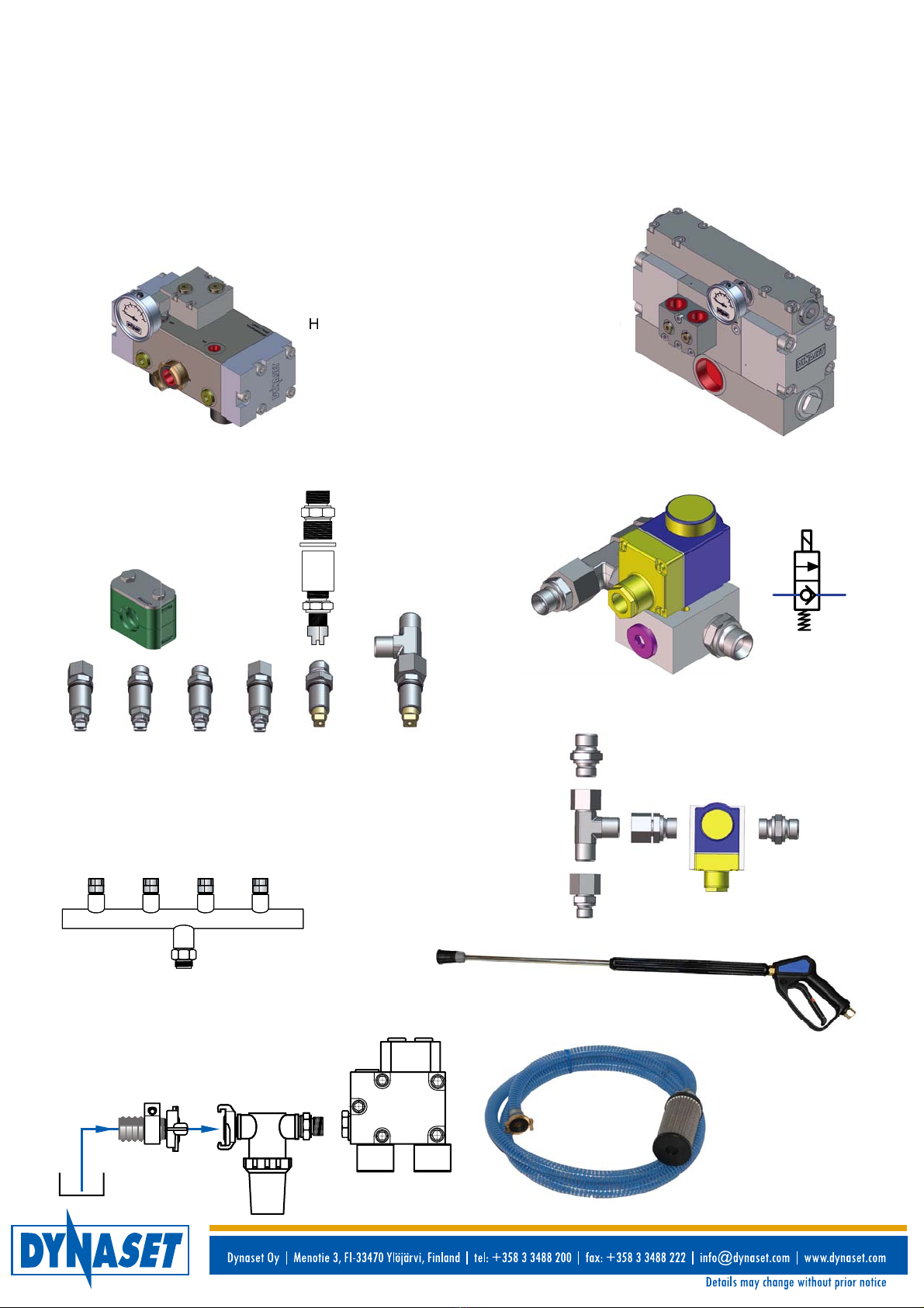
The compact hydraulic operated high pressure pump is easily mounted
onto the machine.
HPW pump is controlled by electric ON/OFF valve on machinery cabin.
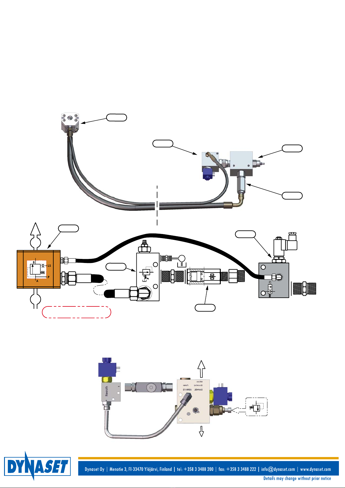
Hydraulic valve kit controls the water pressure with pressure reducer
and the oil flow limiter. Pressure reducer and solenoid valve to
appropriate application control nozzles water flow. Pressure compensated
oil flow-limiter controls the biggest running speed of the HPW-pump.
Excavator fitted Dynaset HPW-Dust suppression system are dual power
stage type. Continuous basic dust suppression is supplement with a
high power mode, which is used as frequently as necessary to suppress
dust created during demolition by fallen debris by bulk-loaded dump on
a truck’s platform etc.
Technically dual stage power output is implemented in two different
ways:
1. In a Dual Water Circuit (DWC), both basic and high power
levels use individual high-pressure nozzle pairs. The high power
dust suppression is switched on by activating separate water
solenoid valve.
High power suppression nozzles can be the first time coarsely
pre-aimed to an assumed dust source according to task demand
and conditions. Exact aiming is done after the experiment.
2. In a Single Water Circuit (SWC), the same nozzle pair is for
both basic and high power dust suppression, using two separate
hydraulic flows – one for each power level of dust suppression.
Prior to switching on the dust suppression, operator have to aim the
attachment with dust suppression nozzles to a dust source.
Front loader’s bucket or mobile crusher’s feed hopper and conveyors
can be equipped with dust suppression-nozzle pipe(s) of a single
water circuit mode continuous mode, dust suppression system
HPW200 Dust.
Nozzles: 8 x
(1,6 lpm 120°)
April 2014 JLe
HPW-DUST HIGH PRESSURE SUPPRESSION SYSTEMS

HPW-DUST DOUBLE BASIC COMPONENTS
5
DUAL WATER CIRCUIT SYSTEM (DWC) components ready for installation and for instantly use, including
following components:
HPW-PUMP 1., PRESSURE REDUCING VALVE 2.2, FLOW LIMITING VALVE 2.3 and SOLENOID VALVE 2.4.
(spraying On) In OC-hydraulic systems, HPW-pump is operated under constant hydraulic pressure. The output
water flow and eventually hydraulic flow is rated by the size of installed water nozzles.
The flow limiting valve is adjusted at factory to the throughput required by high power dust suppression.
HPW90 dust double, PC-SAE 1"-24V, D200105500
HPW90/150-85
2.3 FLOW LIMITING VALVE
ON / OFF -VALVE (CONTINUOUS)
2.4 SOLENOID VALVE (HIGH PRESSURE)
PRESSURE RELIEF VALVE
HPW200 dust double-DWC, D200105350
HPW200/30-45
PV-SAE
NOZZLES:
2 x 6504 (12 lpm 65°)
2 x 6502 (6,4 lpm 65°)
FILTER
ELEMENT
HAND SPRAY
PISTOL
- PUSH AND PULL
BUTTONS
- INDICATOR LAMP
- SOLENOID PLUGS
- CONTROL WIRING
HOSE
April 2014 JLe
HPW-DUST HIGH PRESSURE SUPPRESSION SYSTEMS
2.3 2.2
2.4
1.

HPW-DUST DOUBLE BASIC COMPONENTS
6
Following Hydraulic High Pressure Water Pumps (HPW) are widely used in Dynaset high-pressure dust
suppression systems:
- HPW 200/30-45 dust. 4 x 6,4 l/min nozzles.
- HPW 200/30-45 dust double. Double power spray 20/30 lpm.
- HPW 220/50-70 dust double. Double power spray 30/50 lpm.
- HPW 180/90-115 dust double. Double power spray 30/90 lpm.
- HPW 130/180-140 dust double. Double power spray 30/180 lpm.
HPW 200/30-45 HPW 130/180-140
H
8
0-
14
0
Dust suppression nozzles
installed to a nozzle pipe.
Water nozzle with required
fittings is suitable for both
continuous and intermittent
high power modes.
Nozzles left to right:
- No. 1- 4, 11002 (6,4 lpm 200bar 110º) for
intermittent high power mode.
- No. 5 and 6, 2 x R3/8" (51 lpm 70bar) for
continuous mode.
- No. 7 nozzle attaching clamp.
Water solenoid valve for occasional high-pressure
dust suppression with required fittings.
1. 2. 3. 4. 5. 6.
Water intake hose
with strainer and
claw coupling from
machinery’s
separate water tank.
High pressure spray pistol with 10m hose.
Filter to water intake (claw coupling) from
pressurized water supply, i.e. water from
hydrant, max. pressure 5 bar.
7.
MAIN PARTS HPW90 Dust double, PC-SAE 1"-24V oc. D200105500
April 2014 JLe
HPW-DUST HIGH PRESSURE SUPPRESSION SYSTEMS

7
A HYDRAULIC ACTUATOR VALVE KIT
HYDRAULIC VALVE KIT for a DUAL WATER CIRCUIT SYSTEM (DWC) includes following components:
PRESSURE REDUCING VALVE 2.2, FLOW LIMITING VALVE 2.3 and SOLENOID VALVE 2.4.
In OC-hydraulic systems, HPW-pump is operated under constant hydraulic pressure. The output water flow and
eventually hydraulic flow is rated by the size of installed water nozzles.
The flow limiting valve is adjusted at factory to the throughput required by high power dust suppression.
Valve kit for Open centre hydraulic systems includes pressure compensator PV-SAE pos. 2.1. When installing
to close centre hydraulic system, concerned pressure compensator is not required.
2.2
Pressure reducer
7-210
Flow limiter R3/4 u s
Solenoid valve
2/2 NC
PC-SAE 3/4"
OC-HYDRAULICS 2.3
2.4
2.2
2.1
A
B
T
P
LS
P
LS
2.3
1
3
2
2.4
2.3
Control valve kit for single water circuit system (SWC).
Flow limiting
valve
On / Off -valve Solenoid-valve
HYDRAULIC VALVE KIT for SINGLE WATER CIRCUIT (SWC) SYSTEM provides two separate hydraulic flows,
one for both power level of dust suppression.
Pressure relief valve
HPW200 dust double-DWC, D200105350
April 2014 JLe
HPW-DUST HIGH PRESSURE SUPPRESSION SYSTEMS
P
T

8
HYDRAULIC VALVE KIT for SINGLE WATER CIRCUIT SYSTEM (SWC):
Valve kit includes an adjustable FLOW LIMITING VALVE 2.5 for continuous dust suppression, LS Valve with
FLOW LIMITER 2.6 for high power dust suppression (adjusted in factory), two SOLENOID VALVES 2.7 and 2.8
respectively and PRESSURE RELIEF VALVE 2.9.
By activating the solenoid valve 2.7, the
continuous dust suppression is being started.
Water flow is rated by setting of flow limiting valve
2.5, which can be re-adjusted within certain limits.
Hydraulic fluid flow Q1 is directed to the pressure
port of HPW-pump through above components
and fixed flow limiter 2.6.
The High power dust suppression is switched by activating the solenoid valve 2.8 when system’s operation
(primary hydraulic flow and secondary water flow) is rated tothe fixed flow limiter setting 2.6. Pressure relief
valve protects the equipment against damages.
2.8 2.9
2.6
2.5
Q2
Q1
2.7
Q1
Q2
P
LS
P
LS T
A HYDRAULIC ACTUATOR VALVE KIT
CONTROL WIRING IN DUST SUPPRESSION SYSTEM
HPW-PUMP’S ON-OFF SWICTH
+ 24 VDC
2 x 1,5 mm2
0 yellow
red 2.4
DUST SUPPRESSION SYSTEM WITH DUAL WATER CIRCUIT
HPW-pump is switched on by activating the
hydraulic solenoid valve 2.4. The switch is to
be located in a suitable place inside of the
machinery cabin.
ON-OFF SWITCH
OF BASIC DUST
SUPPRESSION
IN CABIN.
OC-HYDRAULICS
2.1
April 2014 JLe
HPW-DUST HIGH PRESSURE SUPPRESSION SYSTEMS

9
HPW-pump is to be connected to hydraulic system of carrier machine, as well as to pumping fluid circuit.
HPW can be installed with no particular efforts to system based on either constant or variable displacement
hydraulic pump, as well as to closed hydraulic systems.
ATTENTION !
Check the ports of your HPW-pump and connect it to hydraulic and pumping fluid circuits according to their
markings !
If the hydraulic pressure line will be connected by accident to the return port and return line correspondingly to
the pressure port, it will not cause any harm to HPW-pump, however pump will not operate.
In order to reduce both pressure pulsation and return line oscillation, the flexible hose with textile fabric cord is
recommended to be used in return line to protect from damage low pressure units, such as oil cooler.
Prior to connecting HPW-pump to hydraulic circuit, compatibility of used equipment should be ensured.
Hydraulic pressure and flow rate produced by hydraulic circuit should meet values demanded by your HPW-pump.
Refer to the technical specifications.
2.7 2.8
0
2 1
24 VDC from
the 10 A fuse
By activating either of hydraulic solenoid valves with
a rocker or other 3-pole switch, an operator directs
the hydraulic flow of chosen power mode to the
HPW-pump’s pressure port.
The switch can be located onto the dashboard or any
other user-friendly position. When the switch is in the
mid-position, both solenoid valves are disengaged
and HPW-pump stopped.
INSTALLATION TO DIFFERENT HYDRAULIC SYSTEMS
HIGH POWER WATER SOLENOID VALVE’S
BUSH-BOTTON SWITCH
+ 24 VDC
+ 24 VDC
0
0
2 x 1,5 mm2
1.3
High power dust suppression is switched on by activating
the water solenoid valve 1.3. Spring-loaded push-on
button is recommended to place on a boom’s control
stick.
CONTROL WIRING IN DUST SUPPRESSION SYSTEM
DUST SUPPRESSION SYSTEM WITH DUAL WATER CIRCUIT
April 2014 JLe
HPW-DUST HIGH PRESSURE SUPPRESSION SYSTEMS

10
Nozzles for
continuous dust
suppression mode.
INSTALLATION TO DIFFERENT HYDRAULIC SYSTEMS
OPEN CENTRE HYDRAULIC SYSTEMS WITH VARIABLE DISPLACEMENT PUMP
DUST SUPPRESSION SYSTEM WITH A DUAL WATER CIRCUIT
High power dust
suppression nozzles.
Water solenoid valve
for high power dust
suppression.
Water supply from water
hydrant (Max. pressure 5 bar).
AN ALTERNATIVE:
Water reservoir,
intake hose, filter.
DUST SUPPRESSION SYSTEM WITH A SINGLE WATER CIRCUIT.
Dual mode high dust
suppression nozzles.
AN ALTERNATIVE:
Water reservoir,
intake hose, filter.
Water supply from water
hydrant (Max. pressure 5 bar).
High-pressure
spray gun.
High-pressure
spray gun.
PC-SAE
PC-SAE
April 2014 JLe
HPW-DUST HIGH PRESSURE SUPPRESSION SYSTEMS

11
Nozzles for continuous
dust suppression mode.
High power dust
suppression nozzles.
Water solenoid valve for high
power dust suppression.
Dual mode high dust
suppression nozzles.
AN ALTERNATIVE:
Water reservoir,
intake hose, filter.
Water supply from water
hydrant (Max. pressure 5 bar).
INSTALLATION TO DIFFERENT HYDRAULIC SYSTEMS
CLOSE CENTRE HYDRAULIC SYSTEMS WITH VARIABLE DISPLACEMENT PUMP
DUST SUPPRESSION SYSTEM WITH A DUAL WATER CIRCUIT
DUST SUPPRESSION SYSTEM WITH A SINGLE WATER CIRCUIT.
Water supply from water
hydrant (Max. pressure 5 bar).
AN ALTERNATIVE:
Water reservoir,
intake hose, filter.
High pressure
spray gun.
April 2014 JLe
HPW-DUST HIGH PRESSURE SUPPRESSION SYSTEMS

12
High power dust suppression nozzles should be
fastened to an attachment. Position of the nozzles
should be chosen to cover as wide dusting area as
possible. Rotating table or foot of an attachment is
suitable for the purpose.
High power dust suppression is
controlled by means of the water
solenoid valve, which is
recommended to install to a basic
boom’s end in suitable place to be
kept clean and intact.
2 x
4 x
Hydraulic high-pressure water pump HPW is recommended to install onto excavator’s upper structure behind the
boom in order to easy pressure hose lying along the boom down to the nozzles. Install pump with rubber cushions
to reduce noise and vibration.
Water supply hose should be brought to the HPW-pump in the way excluding the hose to be drawn under the
crawler track of the machinery. The water supply hose must constantly be insight of an operator. Water reservoir
(if used) is recommended to lock on an excavator. Water supply hose, provided with filter, is brought in form the
upper lid or hatch.
High power dust suppression nozzles
should be fastened to a attachment
as well. Position of the nozzles
should be chosen to cover as wide
dusting area as possible. Direct
nozzles to the dust source so that
all dust are rounded by the water
mist. See picture right below.
Rotating table or foot of a attachment
is suitable for the purpose.
Nozzles should be shielded with
detachable covers against impacts.
HPW-PUMP
AN ALTERNATIVE:
Water reservoir
2
x
INSTALLING COMPONENTS
MATERIAL FLOW
2 x
NOZZLES x 4
Recommended nozzles e.g. for crushing,
pulverizing or demolition:
- 2515 (48lpm 200bar 25º, Oc. 6306532000)
- 2508 (26 lpm 200 bar 25º, Oc. 6306529000)
April 2014 JLe
HPW-DUST HIGH PRESSURE SUPPRESSION SYSTEMS
WATER MIST
+ DUST
MATERIAL FLOW

13
INSTALLING COMPONENTS
Basic dust suppression nozzles should be installed to an attachment. Their position must ensure water jetting
immediately into the processing zone / area, for instance straight into the zone between crushers jaws, see the
page 1.
Install nozzles into the inter-jaw zone, crusher’s shaft must be provided with a water channel on 6-10mm. Additional
swivel joint is required for the water supply.
If there is no possibility to use swivel water joints, basic dust suppression nozzles is the best place on rotating
table’s rim.
Nozzles for continuous dust
suppression mode attached
to clamps.
2 x 2 x
2
x
Nozzles for continuous dust
suppression mode equipped with
swivel joints on hose branch.
2
x
2
Nozzles for continuous dust suppression mounted
to the crusher’s conveyor with clamps.
4 x
4
x
High pressure dust
suppression nozzles are
effective alternative as well.
April 2014 JLe
HPW-DUST HIGH PRESSURE SUPPRESSION SYSTEMS

14
HYDRAULIC ACTUATOR VALVE INSTALLATION
Hydraulic valve unit, by means of which the necessary
power is taken and brought to the Dynaset HPW-pump,
is recommended to install into the hydraulic pump
compartment of a carrier machine.
The installation of the hydraulic actuator valve of a dual
water-circuit dust suppression system is displayed on the
attached pictures.
Refer also to hydraulic diagrams on pages 9 and10.
65º
(6504)
25º
Area covered 1,1m x 2m = 2,2 m².
If 4 nozzles: 4 x 2,2m² x 0,6 = 5,28 m².
Area covered 0,5 m x 2 m = 1,0 m².
If 8 nozzles: 8 x 1,0 m² x 0,6 = 4,8 m².
0,5 m
0 m 1 m 2 m 3 m 4 m
NOZZLE SPRAY ANGLE THEORETICAL COVERAGE
1,1 m
Pressure compensator installed to a pressure port
of the main hydraulic pump.
An installation of a valve unit include of pressure
reducing valve, flow limiter valve and solenoid valve.
Figures are only exemplifying,
presenting theoretical coverage of
spray patterns at various distances
from nozzle orifice.
Used pressure level, water
temperature, viscosity and water
surface tension have their affects to
spray angle and distance.
Prior to use different kinds nozzles
with DYNASET high pressure dust
suppression system, please be
kindly requested to contact nearest
DYNASET representative for an
advice.
April 2014 JLe
HPW-DUST HIGH PRESSURE SUPPRESSION SYSTEMS

15
HYDRAULIC FLUIDS
Wide range of standard hydraulic fluids can be used with the DYNASET hydraulic equipment.
Subject to the operating temperature, following mineral hydraulic oils are recommended:
ISO VG 32S for oil’s operation temperature up to 70 °C;
ISO VG 46S for oil’s operation temperature up to 80 °C;
ISO VG 68S for oil’s operation temperature up to 90 °C.
Synthetic and bio-oils can be used as well if their viscosity characteristics and lubricating efficiency are
corresponding to above mineral oils. Automatic transmission fluids and even engine oils can be used, provided
that they are allowed to be used in hydraulic system of your carrier machine.
Prior to use special hydraulic fluids a with DYNASET equipment, please be kindly requested to contact nearest
DYNASET representative for an advice.
Having started a machinery and job - for instance, demolition of the building - an operator stars the basic dust
suppression by activating a hydraulic solenoid valve.
Basic dust suppression nozzles catch the dust straight at its source. High power dust suppression can be used
to kill the dusting of bigger objects - a debris pile, fallen fragment, etc.
An attachment with nozzles should be aimed to the dust-emitting object by activating either the water or hydraulic
solenoid valve - depends on system’s structure, see pages 9-10).
The high power dust suppression is intended for discontinuous use, but if the water pipeline is available, the high
power mode can be used on continuous basis when necessary.
OPERATION
PUMPING FLUIDS
High-pressure dust suppression nozzles and HPW-pump required at least mesh 80 (177 μm) water intake strainer.
Observe strainer condition regularly.
If any nozzle’s spray form going to be varying or to be clogged, the nozzle should detach and flushed with clean
water against the working flow direction. Flush suction strainer with water or change it to the new one.
Water based fluids and seawater can be pumped without any special arrangements, however the pump MUST
BE FLUSHED AND CLEANED THOROUGHLY after a working shift with clean sweet water. Same rule applies to
pumping of gelatin and depositing fluids. After having done your job, flush HPW-pump with clean water or suitable
solvent.
Solvents, fuels and oils can be pumped without any special arrangements.
Fluids with abrasives or high content of solids can be pumped as well, but should be kept in mind, that HPW-pump’s
service lifetime is considerably shortened. Pls. note that DYNASET HDF-pump series is especially designed for
pumping of abrasive fluids.
When HPW-pump is going to be used as a self-priming unit with a special or high viscosity liquid, the flow and
self-priming conditions should be evaluated. If the self-priming property cannot be reached, pumping liquid is to
be fed with certain pressure (refer to the TECHNICAL SPECIFICATIONS), or the pump should be used at lower
hydraulic flow.
Furthermore, if pumping solution is aggressive to NBR-rubber, special seals must be used.
HPW-models made of special materials or with coated parts are available by request.
ATTENTION: Preventing freezing nozzles, water circuit and pipeline at HPW dust high pressure suppression
system, draining and air flushing have to perform before ambient temperature reaches 0°C (32°F) or lower.
April 2014 JLe
HPW-DUST HIGH PRESSURE SUPPRESSION SYSTEMS

16
PRODUCT DISPOSAL
Conform to waste legislation, regulations and recommendations in waste disposal and waste recycling
issued by local authorities.
1. Precondition:
• Product is permanently useless or beyond repair.
• Before transportation get off all used agent (oil, cooling liquid) and dirty filters.
Items requiring special handling can normally be done by authorized waste management facility,
if not:
• Separating the base materials, iron, copper, steel, electronics, removing paint, polyester resin,
and insulation tape and/or plastics residues from all components.
• This ‘waste material’ can now be recycled.
2. Deliver the recycling and waste material to waste management facility.
Note! Customer can send the DYNASET equipment for reuse or recycling to the Dynaset Oy or to
other location determinate by Dynaset representative.
• Customer pays shipping cost.
• Equipment must be adequately packed for shipment.
• Shipment documents must contain purchaser’s name, contact information, equipment type and
serial number.
MAINTENANCE
If any nozzle’s spray form going to be varying or nozzle clogged, the nozzle should detach and flush with clean
water against the working flow direction. Flush suction strainer with water or change it to the new one.
Due to small number of moving parts, in normal operating conditions HPW-pump does not require any other
service, except replacement of sealings or occasionally of water valves, which depends on content of abrasives
in pumping fluid, as well as on cleanliness of hydraulic oil.
Check constantly whether the fluid dropping from pump’s leakage detectors is growing and replace sealing in
proper time to exclude intermixing of hydraulic oil and pumping fluid. To enable the easy surveillance, pump
should be kept clean.
Observe also couplings, valves and hoses that they are tight with no bleeding. Clean pump fluid filter and
suction strainer guarantee long components life cycle.
Prior to any cleaning, inspection and service hydraulic system of your carrier machine must be stopped and all
hydraulic fluid circuits depressurized.
WHEN CARRYING OUT ANY DISASSEMBLING OR REPAIR OF HPW-PUMP, ABSOLUTE CLEANLINESS
MUST BE MAINTANED TO ENSURE RELIABLE AND TROUBLE-FREE OPERATION OF YOUR EQUIPMENT.
April 2014 JLe
HPW-DUST HIGH PRESSURE SUPPRESSION SYSTEMS

17
MANUFACTURER’S LIMITED WARRANTY
1. Warranty coverage
All hydraulic accessories manufactured by
DYNASET OY are subject to the terms and
conditions of this limited warranty. Products are
warranted to the original purchaser to be free
from defects in materials or workmanship.
Exclusions from warranty are explained in item 8.
2. Beginning of warranty period
Warranty period begins from the delivery date of
the product. Delivery is considered to be done on
the date when installation has been accomplished
or purchaser has taken the product in use.
Product is considered as taken in use at the date
when DYNASET OY has delivered the product to
purchaser, unless separately agreed otherwise by
written agreement.
3. Warranty period
Warranty period is twelve (12) months based on
maximum of 2000 hours usage during this time
period. In cases where the system is provided
complete with certain special components (e.g.
drive unit), those components are considered as
a subject to their manufacturer’s warranty.
4. Warranty procedures
Immediately upon identifying a problem which
purchaser believes to be a failure subject to the
product’s limited warranty, purchaser must
contact primary to the seller of the product.
Contact must be made as soon as possible, latest
thirty (30) days after the problem was identified.
Seller and/or manufacturer technical staff
determines the nature of the problem primarily by
phone or e-mail. Purchaser commits to give
necessary information and to perform routine
diagnostic procedures in order to determine the
nature of the problem and necessary procedures.
5. Warranty repairs
If the product is found to be defective during the
warranty period, DYNASET OY will, at its option,
either repair the product, author it to be repaired
at its authorized workshop or exchange the
defective product. If the product must be repaired
elsewhere than premises of DYNASET OY or
authorized workshop, all costs excluded from this
warranty (traveling and waiting hours, daily
allowance, traveling expenses and
uninstallation/reinstallation costs) will be charged
from the purchaser.
If the problem is not covered by this limited
warranty, DYNASET OY has the right to charge
purchaser of troubleshooting and repairing.
6. Delivery terms of warranty repair
If the product is found possible to be defective
under this limited warranty and it needs to be
repaired, DYNASET OY gives Warranty Return
Number (WRN). Items being returned must be
shipped, at the purchaser’s cost, adequately
packed for shipment, to the DYNASET OY or to
other location authored by DYNASET OY.
Shipment documents must contain:
- Purchaser’s name and contact information
- Receipt of original purchase
- WRN code
- Problem description
7. Warranty of repaired product
Warranty period of the product repaired under this
limited warranty continues to the end of original
warranty period.
8. Exclusions from warranty
This warranty shall not apply to:
a. Failures due to normal wear and tear,
improper installation, misuse, abuse, negligence,
purchaser selection of improper product to intended
use, accident, improper filtration of hydraulic oil or
intake water or lack of maintenance
b. Cost of maintenance, adjustments,
installation or startup
c. Coating, hydraulic oil, quick couplings and
interconnection hoses (internal or external to system
assemblies)
d. Products altered or modified in a manner not
authorized by DYNASET OY in writing
e. Products which have been repaired during
warranty period by others than DYNASET OY or its
authorized workshop
f. Costs of any other damage or loss, whether
direct, indirect, incidental, special or consequential,
arising out of the use of, or the inability to use, the
product
g. Telephone or other communications expense
h. Product that is used in exceptional conditions,
considered to cause excessive wear and tear
i. Faults caused by nature phenomenon’s like
flood, thunder, etc.
© DYNASET OY, all rights reserved
April 2014 JLe
HPW-DUST HIGH PRESSURE SUPPRESSION SYSTEMS

EC DECLARATION OF CONFORMITY
We hereby declare that the below-reference product design, structure and our
manufacture form fulfills relevant, fundamental safety and health requirements
with the provisions in the Council Directive on mutual approximation of laws of the
Member States on the safety of machines.
- Machine directive 2006/42/EC
- Directive 97/23/EC European standards Pressure equipment.
- LVD directive 2006/95/EC
Apply conformity standards:
- EN60204-1 Safety of machinery – Electrical equipment of machines.
-CEN EN ISO 4413: EN ISO 4413:2010 Hydraulic fluid power - General rules
and safety requirements for systems and their components.
If device has changed by someone other than at the hands of manufacturer or his
permission, this declaration is not valid.
PRODUCT: HIGH PRESSURE DUST SUPPRESSION SYSTEMS
ALL TYPE NUMBERS: HPWxxxxxxxxxx-xxxxxxx-xxxxxxx-xxxxxxxx-xxxxxxxx
YLÖJÄRVI 16.04.2013
DYNASET Oy
Timo Nieminen
R&D Manager
18 April 2014 JLe
HPW-DUST HIGH PRESSURE SUPPRESSION SYSTEMS

19
NOTES
April 2014 JLe
HPW-DUST HIGH PRESSURE SUPPRESSION SYSTEMS

20 April 2014 JLe
HPW-DUST HIGH PRESSURE SUPPRESSION SYSTEMS
Table of contents
Other Dynaset Construction Equipment manuals