SilverLeaf Electronics VMS 333 User manual

VMS 333
Users Manual
6-Button Version
rev.2.7.1

Getting Started
Automatic Video Mode
Whenever the blinkers are on, or when the coach is in Reverse, the unit
automatically switches from (keyboard options) to the all video display mode.
The VMS 333 Keyboard
The VMS 333 is controlled by a small keyboard. The large knob can be turned left
or right, and it can also be pressed. Think of this knob as being the “mouse” for the
computer – it's the main way you provide input into the system.
The keys all have specific functions. Expanded details begin on page 9. While the
VMS 350 is quite versatile, only the installed options will be accessible, based on
your units' configuration.*
View
Pressing this changes screen display; either vehicle information, camera
image or both. Pressing it repeatedly cycles through the 3 different
viewing modes.
House
This key cycles through the set pages of house data to include the Installed
Tanks, Generator, AC and DC Power and Floor Heat monitors.* [For
Forced air HVAC, See THERM.] These pages are described later in this manual
after the configuration settings, beginning on page 9.
Home (The Silvereaf)
This key always returns the system to it's “home page”. This key overrides
all other keys to return the system to the main gauge screen. A second
press enters the Configuration screen and is covered in depth later on.
Therm
This key enters the heating, cooling and ventilation pages.
Chass
This key enters into the three sets of helpful chassis screens.
These are the Tire Pressure page(s)*, Chassis Statistics and Metrics on the
Second page, and Engine/Trans Diagnostics on the Third.
Trip
This key presents current trip statistics and the ability to reset or view prior
trips.
2

The Cursors
Turning and pressing the knob controls the “cursor” icon on the screen. The cursor
has two modes. Pressing the knob switches the cursor from one mode to the other.
Navi ation
When the cursor has a triangular shape, turning the knob will move the cursor
up or down the page.
Adjustment
When the cursor looks like an arrow pointing at its tail, turning the knob will
adjust the setting the cursor indicates.
Home Screen
This screen displays the
most popular important
features at one glance. The
screen has four sections.
Gauge Section
The top portion of the
screen displays five
different engine and
transmission parameters
per 'page.'
Three unique pages then allow for a static choice at the top, such as SPEED, and
four others below it. Use the knob to change which items to display. Turn the knob
to point to the gauge you wish to change, then press it. Turn the knob again to
select a gauge, then press the knob to complete your selection.
Note: Due to variations in engine configurations, some of the gauges included in
the VMS 333 might not be supported by your engine. Also, some annunciators
appear only occasionally, as during generator cran ing.
Whereas most of the gauges are read directly from the engine and transmission, a
few gauges are unique to the VMS 333. In particular, the Real MPG and Recent
MPG are special data items calculated by the VMS 333 to help you get the best
possible fuel economy.
Real MPG shows the fuel economy over roughly the last minute or so, and is
intended to allow you to adjust your driving to get better fuel economy in
headwinds and hills.
3

Recent MPG shows the fuel economy over a much longer period, and provides a
good indication of whether your driving strategy is working overall.
Status Section
Near the center of the screen are two icons which indicate the status of two key
driving parameters.
The Cruise Status icon is blank when the cruise control is off. When the
cruise control is On but not Set, it displays as a small 'c'. When the cruise
control is Set, it becomes a large 'C'.
The Transmission Mode icon indicates whether the transmission is in
“Economy” or “Performance” mode by displaying the appropriate letter.
The mode can be changed by pressing the “mode” key on the shifter pad. If you
drive in “Economy” mode all the time, you will get significantly better fuel
economy at no loss of performance.
Trip Section
The lower right portion of the screen shows four keys values collected from your
current “Trip.” To view these in metric, see the Other Menu Items section below for
the Configuration Screen.
Miles Traveled (“Mls”) and Fuel Consumed (“Gal”) indicates the distance traveled
since the last time the trip odometer was cleared, and the amount of fuel consumed
in that time.
Miles Per Gallon (“mpg”) is a simple calculation from the first two data items.
Note that in the early stages of a trip this value will fluctuate wildly. As the trip gets
longer the value stabilizes.
Miles to Empty (“mte”) is based on the current fuel level multiplied by the Recent
MPG (see above). It will fluctuate according to driving conditions.
Tire Section
This section shows the general status of the tires. For each tire there is an icon, and
the tires are arranged to provide a “bird's eye view” of the vehicle, as though the
vehicle were heading towards the left side of the screen.
This icon indicates that no problem has been detected with this particular tire.
4

This Caution Icon indicates that the pressure in the tire may be below the set
point for the monitoring system in use. For PressurePro, it's 12.5% lower than
than target. For Valor, it represents a lower than set point as programmed by the
coach manufacturer. It can also mean the sensor battery is low or the sensor
temperature is overly hot.
This Warning Icon indicates the tire may be significantly below target.
For PressurePro, this may indicate a pressure 25% below the target. This will
also trigger an audible buzzer which will buzz until you press any key or turn the
knob on the keyboard.
Note that the target pressure is the pressure detected (or programmed in) when the
tire sensor is installed on the tire. For more details, see the Tire Screen section.
PressurePro models may be configured there but Valor cannot and must be factory
serviced.
This icon indicates that no data has been received from the indicated sensor.
If this icon persists for more than a few minutes the sensor should be checked.
To check the actual tire pressures and to get additional detail, press the Detail key
until the Tire Screen appears. See below for more information.
Important Notice
Electronic Tire Sensors transmit the individual tire pressures to the Monitor via
Radio Frequency (RF) signals which can then be displayed in real time.
PressurePro Sensors read tire pressure every 7 seconds and transmits the updated
readings to the Monitor. Some of these transmissions will be interfered with.
Because of the nature of RF, no guarantee of signal reception can be made.
PressurePro is not meant to function as a precise pressure gauge or a low pressure
indicator. PressurePro is a tire pressure monitoring system that displays tire
pressures and which, when a signal is received, will signal low pressures.
Trip Screen
Pressing TRIP gets the first detail screen;
displaying information on your current trip.
The unit tracks two trips simultaneously.
You might use the main trip to track your
mileage and fuel, say, each time you leave
home, while the “auxiliary” trip keeps a
cumulative total for the season or year, or
you could reset it every time you refuel.
5

Mi es to Go
You can use the knob (push) to set this value you'll see multiple pushes
changing the cursors position. As you drive the VMS 333 will count down the
miles, and provide a continuing estimate of your Time of Arrival and the amount of
Fuel Required. These estimates will be based on the speed and fuel consumption
averages for the Main Trip.
By entering in the miles to your destination, say from a GPS, you can get a
good estimate of the arrival time and especially the fuel required, which helps you
plan your stops. Or, you can watch the Arrival Time while adjusting the Miles to
see how far you can go on your next travel leg.
C earing the Trips
By pressing the knob while the cursor points to the Reset Main Trip or Reset
Aux Trip items, you can tell the unit to zero out either of the two trip odometers.
Once cleared, you cannot “undo” the action.
Trip History
When you clear the Main Trip odometer, the data is recorded in the Trip
History. The unit can store up to 64 trips in its history. To view the history, select
the View History item. You can then use the knob to scroll through all the trip data.
Trips of less than five miles are not recorded in the history. To clear the history, see
the Configuration Screen described below.
Tire Screen
Pressing CHASS expands the view of the tire Configuration and Status. If
PressurePro is installed and enabled it shows also the current pressure of each tire.
The top half of the screen is identical to the Tire section of the Main Screen. The
bottom half displays the tire pressures, in PSI. Both sections are arranged in the
same way, as a bird's eye view of the vehicle, driving towards the left.
Tire Configuration
This first screen gives a nice presentation of tire status while pressing the knob
accesses the Tire Pressure Details Screen.
The second press screen allows you to check for detailed sensor information
and, if PressurePro is installed, to move, delete, or add tire sensors as shown:
6
Use the knob to move from position to position. The top left position corresponds
to the curb side front tire. On the bottom half of the screen the detailed information
on the indicated tire sensor is displayed. To view these in metric, see the Other
Menu Items section below regarding the Configuration Screen. The data items
include:
•PSI. Tire pressure.
•Deg. Tire temperature, within 40 degrees Fahrenheit.
•Target PSI. The target pressure, which is the pressure when the sensor was
placed on the tire.
•Signal. The signal strength. Values less than 40 when the vehicle is stationary
indicate that sensor reception might not be reliable.
•Counts. The number of tire reports received.
•Status. There are several possible status values. “New” and “Seen” are
normal values indicating that the sensor has been detected. “Lo Bat”, “Lo
PSI”, “Hi PSI”, “Hi TMP” all indicate high or low battery levels, tire pressure
or temperature. “Signal” indicates the sensor is not being received reliably.
To install a new sensor, move the cursor to the desired position, then press the knob.
Screw the sensor on the tire. Within 30 60 seconds you should see a “No Data”
icon in the desired position, and shortly after than you should see a regular tire icon.
It can take up to five minutes before all the tire data, such as signal strength, is
collected for the new sensor.
To delete a tire, move the cursor to the desired position and press the knob. To
move a sensor from one tire to another, delete it from the original position, then
follow the installation procedure just described.
The sensor itself should be removed and allowed to sit for about two minutes before
being reinstalled.
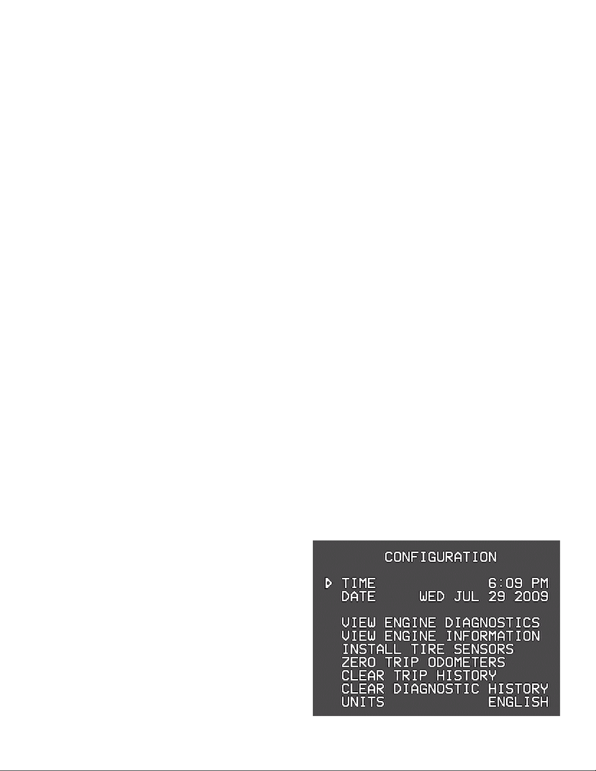
Configuration Screen
Press “Home” (the leaf) twice to adjust the
time and date, view engine diagnostics,
other details and features of the VMS 333.
Adjusting the Time and Date
Turn the knob to point the cursor at either
the Time or Date, then press the knob. A
portion of the time or date will start
blinking, and turning the knob will adjust
that value. Press the knob again to adjust the next portion, and continue until done.
7

Other Menu Items
•View Engine Diagnostics. This item displays a screen showing diagnostic
data from the engine. Current faults are displayed along with a history that
can be scrolled through.
•View Engine Information. This item displays a variety of additional engine
statistics.
•Configure / Install Tire Sensors. This item displays the Tire Pressure Details
screen.
•Units. This allows you to select English or Metric. There are three settings.
“English” sets all units to report in English units (miles, Fahrenheit, gallons,
etc.) “All Metric” sets all units to Metric (kilometers, Celsius, liters, etc.)
“Metric Distances” sets only the speed and odometer units to metric and is
convenient when driving in Canada or Mexico.
•Zero Trip Odometers. This items resets the trip odometers, making it as
though the trip odometers were last reset the day the vehicle was built.
•Clear Trip History. This clears all trips from the trip history.
•Clear Diagnostic History. This clears all diagnostic codes from the diagnostic
history.
•View Communications. This is for troubleshooting and useful during
installation.
•Twea Display. This allows you to optimize the VMS 333 for the particular
video display, allowing for shifting the screen slightly, brightness and contrast.
•Adjust Fuel (Sensor) Settings. This allows you to fine tune the fuel readings,
adjust how MPG is factored or to build in a 'reserve' fuel buffer.
•Restore Default Settings. This returns the unit to its factory defaults.
•Reboot. This restarts the unit.
•Installer Options. This allows access to certain advanced options, usually
accessed only during installation.
House Features
These features are solely house centric. Pressing this button toggles
between The HOUSE specific controls and the Silverleaf Logo.
Your five sub menus may vary depending
on firmware level and manual setup (or
options script.)
TANKS
Pump & Hookup status
Tank Levels in percent
8

Water System Controls (pg 1)
Water Pump Status
AutoFill
Quit – Return to House Screen
GENSET
GENSET (Generator)
GenSet model, Hours and AGS status
More thorough information is available by
way of this document:
“Si verLeaf Genstart Guide 2.pdf”
Available in our Downloads section at
Silverleafelectronics.com?q=node/10
GENERATOR (pg 1)
GENSET Status
AGS Lock
Running Mode
Autocharger
Exercisor
Zone 1 AGS
Zone 2 AGS
(Zone 3, bay, unused)
GENERATOR (pg 2)
Zone 4 AGS
Zone AGS status
Quiet Time, Begin and End
Autocharger Voltage
Topoff Voltage, Runtime and Status
Chassis Charger
9
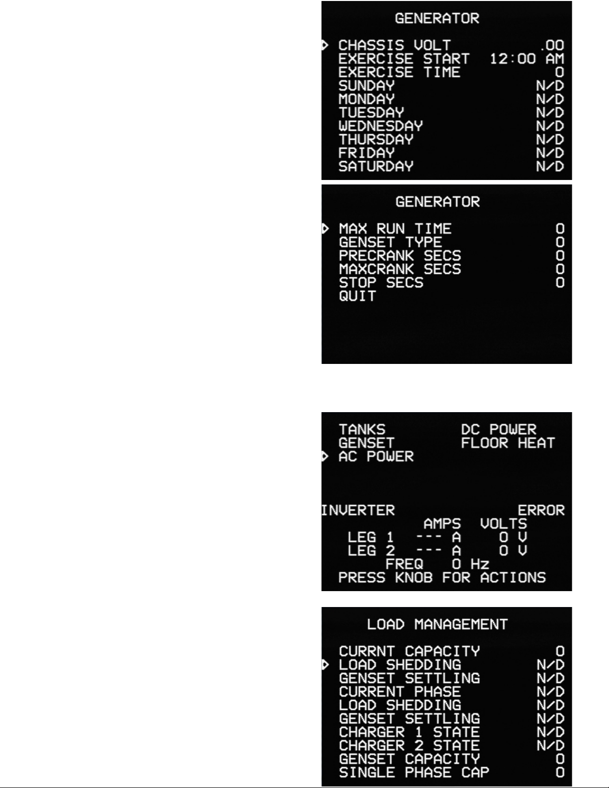
GENERATOR (pg 3)
Chassis Voltage
Exercise Start / Time
(and its weekly schedule)
GENERATOR (pg 4)
[Exercise] Max Run Time
GenSet Type
Precrank (in Seconds)
Maxcrank (in Seconds)
Stop (in Seconds) Preset time for
button press to actually shut off genny.
Quit – Return to House Screen
AC POWER
AC Power – Inverter status, Current (amps),
Voltage & Frequency
Load Management (Page 1)
Current Capacity
Load Shedding [Enabled / Disabled]
GenSet settling [Enabled / Disabled]
Current phase
Load Shedding [Active/ Inactive]
GenSet settling [Active/ Inactive]
Charger 1 State
Charger 2 State
GenSet Capacity
Single Phase Capacity 10

Load Management (Page 2)
Dual Phase Capacity
Charger 1 Shed
Charger 2 Shed
AC Loads (multiples)
Quit
DC POWER
DC POWER – House & Chass Voltage,
Charger status, Total Amp draw
Inverter / Charger (page 1)
Charger 1 MAX
InverterX (1 or 2)
ChargerX (1 or 2)
DC Disconnect
INV1 Settings
FLOOR HEAT
Zone Status
11

Floor Heat (1)
Zone1 /2 /3................ON / OFF
Schedule...........
AM Begins
AM Ends
AM Setting
PM Begins
Floor Heat (2)
PM Ends
PM Setting
QUIT
Troubleshooting
Fault Detection
In the event of a detected fault within the house systems, a fault indication
may appear. As not all coaches are using these and other specific features, your
mileage may vary. Call us for any questions regarding these or other questions.
2

Notes
13

14

15

Limited Warranty
The obligation of SilverLeaf Electronics under this warranty shall be limited to repair or
replacement (at our option) during the warranty period of any part which proves defective in
material or workmanship under normal installation, use, and service, provided the product is
returned to SilverLeaf Electronics. The warranty period shall be one year from date of purchase
of the VMS 333™, or purchase of the finished coach with the VMS 333™ installed.
This warranty shall be invalid if the product is damaged as a result of defacement, misuse,
abuse, neglect, accident, destruction, alteration, improper electrical voltages or currents, repair
or maintenance by any party other than SilverLeaf Electronics or an authorized service facility,
or any use violative of instructions furnished by us.
This one year warranty is in lieu of all other expressed warranties, obligations, or liabilities.
Any implied warranties, obligations, or liabilities, including but not limited to the implied
warranties of merchantability and fitness for a particular purpose, shall be limited in duration to
the one year duration of this written limited warranty.
In no event shall SilverLeaf Electronics be liable for any special, incidental, or consequential
damages for breach of this or any other warranty, expressed or implied, whatsoever.
This warranty gives you specific legal rights, and you may also have other rights which vary
from state to state.
16
SilverLeaf Electronics, Inc.
2490 Ferry Street SW.
Albany, OR 97322
Worldwide: (54 ) 967-8
Toll Free in US: (888) 74 -0259
w w w . s i l v e r l e a f e l e c t r o n i c s . c o m
Table of contents
Other SilverLeaf Electronics Automobile Accessories manuals


Popular Automobile Accessories manuals by other brands


Kenwood
Kenwood CAX-HL10QI instruction manual

MegaTrend
MegaTrend SA-40 quick start guide

Blaupunkt
Blaupunkt BT Drive Free 111 user manual

Rhino-Rack
Rhino-Rack Road Warrior Fitting instructions

Hollywood Racks
Hollywood Racks Sportrider HR1500 Assembly and installation instructions

Panasonic
Panasonic CYBT100U - CAR AUDIO operating instructions