SilverLeaf Electronics VMS 240 CL User manual
Warranty
The obligation of SilverLeaf Electronics, Inc. under this warranty shall be
limited to repair or replacement (at our option) during the warranty period of any
part which proves defective in material or wor manship under normal installation,
use, and service, provided the product is returned to SilverLeaf Electronics, Inc..
The warranty period shall be one year from date of purchase of the VMS™, or
purchase of the finished coach with the VMS™ installed.
This warranty shall be invalid if the product is damaged as a result of
defacement, misuse, abuse, neglect, accident, destruction, alteration, improper
electrical voltages or currents, repair or maintenance by any party other than
SilverLeaf Electronics Inc. or an authorized service facility, or any use violative of
instructions furnished by us.
This one-year warranty is in lieu of all other expressed warranties,
obligations, or liabilities. Any implied warranties, obligations, or liabilities,
including but not limited to the implied warranties of merchantability and fitness
for a particular purpose, shall be limited in duration to the one-year duration of
this written limited warranty.
In no event shall SilverLeaf Electronics, Inc. be liable for any special,
incidental, or consequential damages for breach of this or any other warranty,
expressed or implied, whatsoever.
This warranty gives you specific legal rights, and you may also have
other rights which vary from state to state.
SilverLeaf Electronics, Inc.
2490 Ferry St. SW
Albany, OR 97 22
Worldwide: (541) 967-8111
Toll Free in US: (888) 741-0259
w w w . s i l v e r l e a f e l e c t r o n i c s . c o m
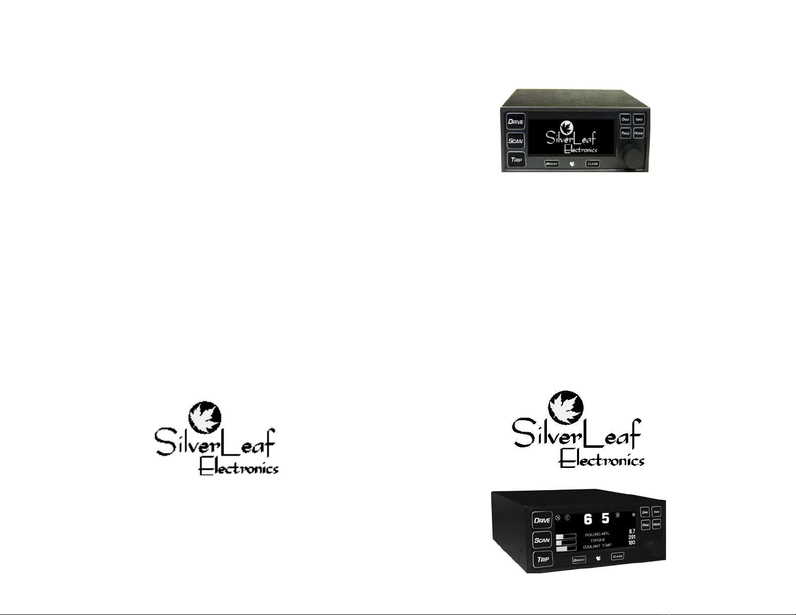
VMS 240 CL™
Owner’s Manual
RV Version 4.0

Quick Start Guide
To Start a Trip
Press TRIP. The Main Trip Screen should appear. Press CLEAR to reset
all values to zero. The VMS will now automatically begin accumulating trip
information. The previous trip will be stored in the Trip History. (See Page 7).
To Set Your Destination “Miles-To-Go”
Press TRIP. The Main Trip Screen should appear.
Press CLEAR to clear previous trip data.
Turn the KNOB. The Miles To Go number near the bottom should adjust
up or down accordingly. Press the KNOB to add 100 miles.
To Read Diagnostic Information
If the Chec Engine indicator on the dash lights up, press DIAG. The
Engine Diagnostics Screen should appear, showing the cause of the problem.
Press DIAG again to see the historical log.
To Set the Time
Press PROG twice. The Cloc Set Screen should appear.
Turn the KNOB to highlight the word “Time”.
Press the KNOB. Turn the KNOB to adjust the hours, and press the KNOB.
Turn the KNOB to adjust the minutes, and press the KNOB. Turn the KNOB to
adjust the AM/PM indicator, and press the KNOB. The cloc is now set.
To Scan Multiple Gauges
Press SCAN. The Scan Screen should appear, and every several seconds the
gauge should change. The green arrow in the upper right corner indicates that
the unit is “scanning”. Pressing SCAN will set the unit in Watch mode, and the
arrow will turn to a red stop sign. Pressing SCAN again will return it to Scan
mode. To change the list of gauges the unit scans, see Page 12.To Watch a
Particular Gauge, press SCAN. Then turn the KNOB until the desired gauges
appears.
To Adjust the rightness of the Display
Press the BRIGHT button. 3 levels of brightness are available.
To Select the Gauges on the Drive Screen
Press PROG. Then turn the KNOB to the second page of configuration items.
Highlight Gauge 1, press the KNOB, turn the nob to choose the desired gauge,
and press the KNOB again. Do the same for Gauges 2, 3, 4, 5, and 6.
Hidden Screens
In addition to all the features
already described, the VMS 240 also has a
set of hidden screens that provide
diagnostic information on the VMS and
data bus, and allow further settings to be
adjusted. Usually these screens are useful
only in the installation of the VMS. But in
certain situations they may prove useful,
so some brief mention is made here.
The most important hidden screen is accessed by pressing DIAG and
INFO simultaneously and holding them for three seconds. The VMS Options
Screen will appear. There are several items on this screen, which you can
scroll through using the KNOB.
Clear Trip History
Trip History
Highlight this and press the KNOB to clear all the trips in the Trip History Screen.
The current number of trip in the history is provided. The maximum capacity is
4096.
Clear Engine History
Highlight this and press the KNOB to clear all the diagnostic codes in the
Engine History. The current number of events in the history is provided. The
maximum capacity is 4096.
Clear All Trips
Highlight this and press the KNO to reset the trip information in the Main
Trip and Alternate Trip Screens. Those screens will show the current trip as
having started when the engine was built.
Clear Maintenance Log
Highlight this and press the KNOB to clear the Maintenance Manager.
Reset To Defaults
Select this to reset all VMS settings to their factory default values.
Accessories
A variety of accessories are available for the VMS. These accessories
are activated via the hidden screen. They should only be activated if a particular
accessory is installed.
Accessories include:
1. Tire Pressure Monitoring (Coach and Towed Available)
2. Weather Station
3. Acutrac Fuel Sensor
4. Road Watch (Road Temp Sensor)

Special Screens
Press HOME to view any special features that may be present on your
VMS 240. If no special features are available, the Splash Screen will appear.
Theft Deterrent (Cat Engines Only)
Cat engines are equipped with a unique
theft deterrent that allows the VMS to loc the
engine electronically. Once loc ed the engine
cannot be started until unloc ed by the VMS or a
professional mechanic’s service tool.
Before loc ing the engine, be sure
to select a code that you will remember. The code consists of three numbers,
each from zero to ninety-nine. If you forget your code, it is possible to unloc
your engine, but not without the assistance of a Cat mechanic or a call to the
SilverLeaf Electronics hot line.
This feature is disabled by default. Near the top of the screen will
appear a message “Disabled” or “VMS OK”. If it’s disabled, go to the VMS
Preferences Screen and change the Anti-theft setting.
The engine status will be shown near the middle of the display. It
should normally read “Loc ed” or “Unloc ed”. The procedure for loc ing and
unloc ing are exactly the same, except you may enter any numbers to loc the
engine. You must enter the exact same numbers to unloc it again.
Turn the KNOB to dial in the first code number. Press the KNOB.
Turn the KNOB to dial in the second code number. Press the KNOB.
Turn the KNOB to dial in the third code number. Press the KNOB. The
VMS should beep, and within a moment the engine status will change.
The theft deterrent will not wor when the vehicle is moving. On some
engines the engine may be running, in which case the engine will shut down
upon being loc ed. On other engines, however, the engine cannot be running
when you loc it. The engine will simply ignore the VMS and remain unloc ed.
Table of Contents
Quick Start Guide ................................................... 2
Drive Screens .......................................................... 4
Scan Screen ............................................................ 5
Trip Screens ..............................................................7
Diagnostics Screens ................................................ 8
Information Screens ................................................. 9
Programming Screens ........................................... 11
Special Features ..................................................... 13
Special Screens ...................................................... 14
Hidden Screens ...................................................... 15
Warranty ................................................................. 16
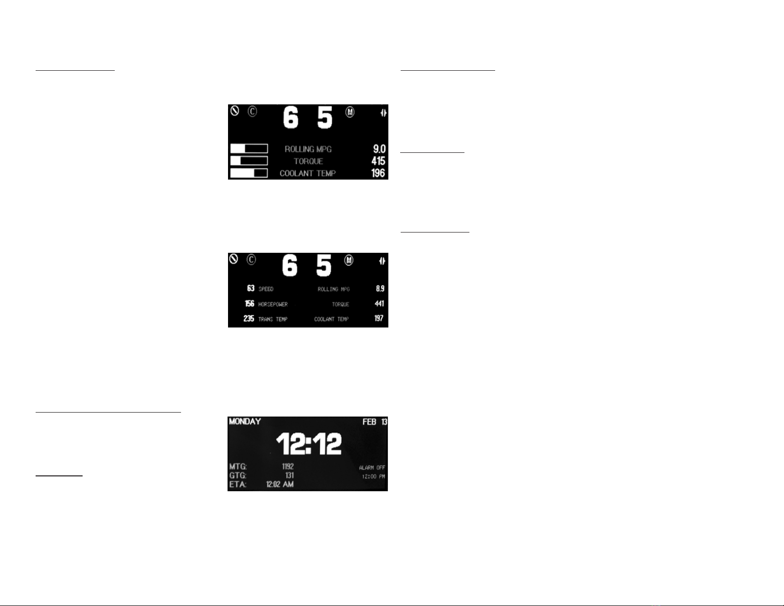
rive Screens
Pressing DRIVE brings up one of the Drive Screens. There are two
variations, a Three gauge and a Six gauge version. Pressing the ey again
selects the next version.
On either Drive Screen, you can
press the bright button to adjust the
brightness of the display. Both Drive
Screens display transmission and cruise
control information in the top portion of the
screen. The moving icon in the top left
corner indicates that the VMS is successfully communicating with the chassis.
The (C) icon will disappear when the Cruise Control is off. It will turn solid when
the Cruise is active.
The two large numbers at the top center indicate the Gear Selected and
Gear Attained by the transmission. You should see these update as the
transmission shifts. To the right, the VMS displays the Transmission Mode,
Operating Error, and Torque Converter
Status. The Mode indicates the
aggressiveness of the transmission; on
most coaches Mode On indicates less
aggressive shifting for better fuel economy.
The Error icon (an exclamation mar ) will
appear to indicate problems. The Torque
Converter icon will usually be closed, indicating the converter is loc ed. At lower
gears the converter opens for starting and shifting.
All three gauges in the first Drive Screen and all six in the second Drive
Screen are user selectable. (See Page 11)
Clock Drive Screen
Clock, Calendar and Alarm Clock
The cloc , calendar, and alarm
cloc can be set using the Cloc Set
Screen, activated by pressing PROG twice
and viewed by pressing RIVE 3 times.
Trip Status
On the lower left, the VMS displays
the Miles-To-Go (MTG), Gallons-To-Go
(GTG), and Estimated-Time-of-Arrival (ETA). The MTG is set on the primary Trip
Screen (see the Quic Start page), and will slowly count down as you drive. The
GTG and ETA are constantly being recalculated based on fuel
economy and speed. In the first miles of each trip it will fluctuate before settling in
on it’s best estimate, which will change as conditions warrant. These can be set
to read in Metric using the VMS Settings Screen.
Special Features
The VMS has certain special features that monitor “behind the scenes” and
change the display according to the demands of the situation. These features
wor automatically, and require no user effort. They can be turned on or off via
the “hidden” configuration screen described in the last section of this manual.
Cruise Monitor
The VMS watches for any activity on the Cruise Control switches (set,
accelerate, resume, coast), and automatically switches the display to the Scan
Screen and shows Cruise Set Speed. The screen will stay on that item until the
driver lets off the cruise switches. After a few seconds, the VMS will return to
displaying whatever screen it was on before.
Trouble Monitor
The VMS watches for any of a number of possible problems, and automatically
switches the display to the appropriate screen and gauge. High Coolant or
Transmission Temperature, or Low Battery Volts will switch the display to the
appropriate Scan Screen gauge. A Chec Engine condition will switch the
display to the Engine Diagnostics screen. The unit will stay on that screen until
the user presses a ey. It will then function normally and will not automatically
return to that gauge or screen unless another problem occurs.

features to function properly.
AntiTheft
This setting allows you to disable the Theft Deterrent feature, available
with Caterpillar engines. Disabling this feature prevents inattentive people from
accidentally loc ing the engine and forgetting the code.
Chassis
This selection is required for the Maintenance Trac ing screens. If your
chassis is not in the list, select “OTHER” to get a fairly representative set of
maintenance intervals.
Trip Units
This determines whether trip information is displayed in Metric or
Standard units.
Gauge 1,2,3,4,5,6
These determine the gauges shown on both Drive Screens.
Trans Type
Select the transmission type. Older Allison transmissions have a dual
readout on them. This readout shows gear selected as well as gear attained.
Trans type would be set to “WTEC” for this transmission (The VMS will not
show gear status in this mode). The newer type shifter with the single readout
that just shows gear selected. Setting trans type to “WTEC V8” will allow the
VMS to display gear selected and gear attained on the drive screens.
Scan Preferences Screen
Press PROG three times to activate the Scan Preferences Screen. A list
of gauges available in the Scan Screen will appear, with their settings for the
Watch and Scan modes. Each gauge may be set to Watch or Hide, and Scan
or S ip. A gauge set to Hide will not appear in the Watch mode at all, while it is
set to Watch it will be accessible in the Watch mode by turning the nob. A
gauge set to Scan will appear periodically in the Scan mode. Typically most
gauges should be set to Watch, but only the most important should be set to
Scan.
The third column allows you to select English or Metric units. Each
gauge can be set independently of the others.
Turn the KNOB to select a particular item. (there are more than can fit on
the screen at one time). Press the KNOB to change the values.
Automatic Sensor Detection
No engine supports all the gauge functions the VMS is capable of
displaying. The VMS is capable of querying the engine to determine its
capabilities, and it can automatically set the unsupported gauges to “Hide”. To
activate the sensor detector, let the VMS run for at least ten seconds while this
screen is activated, and press CLEAR. All features supported by the engine
should be set to Watch and Scan, while others are set to Hide and S ip.
Scan Screen
The Scan Screen provides the equivalent of over a dozen gauges in
one pac age. The specific gauges depend on the engine model and
configuration, and additional items may be available if additional sensors are
installed.
Press SCAN to activate the Scan Screen. Near the top right corner is an
icon that indicates the screen “mode”, Scan or Watch. A green arrow icon
indicates Scan, a red stop sign indicates Watch.
Note: For the Scan Screen to wor properly, the correct engine must be
selected. The engine type is set in the VMS Preferences Screen, described on
page 11.
Scan Mode
In Scan Mode, the VMS will cycle
from gauge to gauge, displaying each one
for a set amount of time. You can program
the gauges provided in this mode, and the
amount of time spent showing each one,
using the VMS and Scan Preference
Screens. (See pages 11 & 12.)
Each gauge can be displayed in two ways. The Graphic gauge shows
the gauge value and two graphs. At the bottom of the screen is a simple bar
graph indicating the current value. To the right is a histogram which shows how
the value has fluctuated over the last minute. A flat graph indicates that the
value is stable, and is not changing significantly.
The Numeric gauge displays just the value as a large number. This
gauge is easier to read than the Graphic gauge, but it doesn’t provide the
histogram showing fluctuations.
Press the KNOB to change a particular gauge from Graphic to Numeric
or bac . Each gauge may be set independently, and the VMS eeps the setting
in its permanent memory.
Press SCAN to enter Watch Mode. The VMS will stop scanning, and
stay on the current gauge.
Turn the KNOB to dial in a particular gauge. The unit will automatically
enter Watch Mode. Individual gauges may be set to display metric values using
the Scan Preferences screen described in a later section. (See page 12)
Watch Mode
In Watch Mode, the gauge will not change. This is useful when you are eenly
interested in one particular gauge - such as the Coolant Temperature during a
very hot day. You can change the gauge by dialing with the KNOB. The gauges
are arranged in alphabetical order. Press SCAN to resume Scan Mode. Press
the KNOB to change the gauge from Graphic to Numeric or bac .
Gauge Items

All gauge items are obtained directly from the engine and transmission,
and are digitally accurate. In general, the VMS is much more reliable and
accurate than the
conventional dash gauges.
Most gauges are self-explanatory. Some, such as Accelerator Position,
are useful only in certain troubleshooting situations. Some duplicate the dash
gauges, but are more accurate and precise than the conventional gauge.
Others are truly unique, such as Torque.
Engine Coolant Temperature
When driving in hot weather and wor ing the engine hard, we
recommend using this gauge in Graphic Mode. Most engine experts agree that
you should start “managing” your temperature when it reaches about 210
degrees. From that point on your goal should be to stabilize the temperature
before it reaches 225 or higher. In Graphic mode, a flat histogram indicates the
temperature is stable. (Engines models vary somewhat in their tolerance for
heat. Chec your engine manual for details on your engine.)
Horsepower and Torque
These gauges show the calculated engine output. The VMS cannot
compensate for fans, belts, and other parasitic loads on the engine, and this
value may be thrown off by a malfunction in the engine. But it does provide an
effective indicator of engine performance. Of the two, Torque is more indicative
of motive force and efficiency. When wor ing the engine, try to maximize your
torque output. At very low RPMS these values cannot be accurately calculated.
Under these conditions both of these gauges will read zero.
Rolling MPG, Instantaneous MPG, Recent MPG, and Power Factor
Instantaneous MPG indicates the fuel economy calculated on a
moment-by-moment basis. It generally fluctuates too rapidly to be useful for
guiding your driving, so the VMS calculates a Rolling MPG. Rolling MPG
considers fuel consumption over roughly a one minute time interval, while
ignoring very low speed driving and idling. It provides a very good indication of
your current fuel economy, and is a useful tool for adjusting your driving to get
the best fuel economy. Recent MPG calculates mileage over the course of
approximately 20 minutes giving a better overall picture of trip progress. Power
Factor indicates the efficiency with which the engine is converting fuel to power.
Although it is a good indicator of pure engine efficiency, it is generally not
correlated to overall vehicle efficiency, since it does not consider air resistance,
rolling resistance, and parasitic loads.
Unsupported Gauges and Zero Readings
Not all engines support all gauges, and some gauges require additional
sensors or accessories that may be available as aftermar et installations.
These gauges will show a reading of Zero all the time. These gauges can be
removed by using the Scan Preference Screen (described on page 12), and
setting them to “Hide”. Rarely a bug in the engine ECM may cause a zero
reading in an important gauge such as Turbo Boost Pressure. This can
generally be fixed by an engine technician. Consult your engine manufacturer
or SilverLeaf Electronics if you have any questions about whether your engine
supports a particular gauge.
Programming Screens
Clock Set Screen
Press the PROG twice to activate
the Cloc Set Screen. This screen allows
you to set the date and time, and set and
activate the alarm cloc .
To set the time, turn the KNOB
until “TIME” is highlighted. Press the
KNOB, then turn the KNOB to adjust the hour. Press the KNOB, then
turn it to adjust the minute. Then press it and turn it to adjust the AM/PM value.
Press the KNOB a final time to return to the “TIME” position.
Setting the date follows exactly the same process, as does setting the
alarm cloc . To use the alarm cloc you must set the alarm time and also set
the “ALARM SET” value to “SET”.
The alarm cloc will sound at the appropriate time, but obviously the
VMS must be on at that moment. If the VMS is turned off and on again, the
alarm cloc will remember its status and will sound at its appointed time. The
alarm will sound until any ey is pressed on the VMS. After sounding, the Alarm
Set value will return to OFF.
VMS Preferences Screen
Press PROG once to activate the
VMS Preferences Screen. Here is where a
variety of parameters can be adjusted to
match your coach configuration and
personal preferences.
Use the KNOB to adjust each
item. Turn the nob to highlight the
parameter name, press the KNOB, and turn the KNOB again to adjust the
value. Press the KNOB again to return to the parameter name and the setting
is complete.
Scanning Speed
This is the number of seconds that the Scan Screen will spend on
each gauge when in Scan Mode. A lower number will ma e it scan faster.
Brightness - High and Low
Press the BRIGHT button to adjust brightness on the screen. There are
4 different brightness settings.
Palettes
This switches the bac ground color for better viewing in different
conditions.

Engine
This indicates the engine ma e and model. This must be set correctly
to allow all
tions. You can use the VMS to indicate when you have each of these
groups performed, and the VMS will calculate when each group is due
again.
Turn the KNOB to select a particular service group. The items in the
group will be displayed, along with the date and odometer reading from the last
time the service was performed, and when the service is due to be performed
again. A face will show whether the item is due.
Press CLEAR to indicate that the displayed service group has been
performed. The display should update to show the current date and odometer
reading.
Press the KNOB to manually adjust the date and odometer reading. You
can use the KNOB to adjust the month, date, year, and odometer reading for
each item. Thus if you fail to press CLEAR at the time of service, you can enter
the information later.
This feature is not intended to replace your service records. It is always
a good idea to keep your service receipts
for the protection of your warranties and
for the benefit of future owners should
you sell your coach.
Warning: Chassis service items and
intervals can change. We attempt to make this service information thorough
and accurate, but the VMS is not a replacement for your manuals. Please
consult your engine, transmission, chassis, and other manuals for up-to-date
information on your vehicle.
Pre-Drive Checklist
Press INFO again to activate the Pre-Drive Chec list. This screen shows
a long list of items that are occasionally forgotten by drivers before moving the
coach. It can be used li e a pilot’s “pre-flight” chec list.
Turn the KNOB to scroll through the list. The initial list contains over thirty
items.
Press the KNOB to indicate that the item has been performed. The VMS
will put a chec mar by the item. If you leave this screen and return, the
chec mar will still be there. But if you turn the VMS off, the chec mar will
disappear.
Press CLEAR to remove an item from the list. The item will remain off the
list even after the VMS has been turned off. This allows you to edit the list to
your personal li ing. The only way to bring the item bac onto the list is to clear
every item off the list. The VMS will then put every item bac on the list,
returning the list to its original condition.
Trip Screens
Press TRIP to activate the Main
Trip Screen. Press TRIP again to activate
the Aux Trip Screen. Press TRIP a third
time to activate the Trip
History Screen. You can convert these
screens to metric units using the VMS
Preferences Screen.
Main Trip Screen
The top portion of the screen show the Distance travelled during this
“trip”, the number of hours and minutes the engine was running, the average
speed, and the gallons of fuel used. The hours and MPH values are based on
engine run time, not the total elapsed time. Sitting and idling the engine will
affect these values, but sitting with the engine off will not. The center of the
screen shows the Miles Per Gallon achieved on this trip.
The bottom portion of the screen is dedicated to the Trip Planning
feature. Use the nob to set the expected number of miles you plan to travel
today. The VMS will slowly count down as you drive, and calculate the gallons
of fuel required to reach your destination, and the estimated time of arrival.
These will constantly be recalculated as you drive, and are based on your
average fuel economy and speed for this particular trip.
Press CLEAR to start a new “trip”. All values on the screen will reset to
zero. The information on previous trip will be stored and is available on the Trip
History Screen. (Trips of less than .2 miles
are not saved.)
Turn the KNOB to adjust the
Miles-To-Go in 1 mile increments and
press the KNOB to add 100 mile
increments to the Miles-To-Go.
Alternate Trip Screen
The Alternate Trip Screen is identical to the Main Trip Screen, with two
differences. First, there is no Miles-To-Go feature on this screen. Second, trips
on this screen are not saved in the Trip History. This screen can be used to
provide a “grand total”, or for a tan -by- tan trac ing of fuel. Clearing this trip
has no effect on the Main Trip.
Press CLEAR to start a new “trip”. All values on the screen will reset to
zero.
Trip History
The VMS stores up to over 4000
trips as they are cleared from the Main Trip
Screen. They can be viewed on this

screen. The screen displays the date the trip ended, the miles travelled, fuel
used, engine running time, average speed, and fuel economy (MPG).
iagnostic Screens
Whenever the engine detects a problem, it activates the heck Engine light on
the dashboard. At the same time it transmits a series of codes which a mechanic can
pick up using his “scan tool”. The VMS also picks up those codes, stores them, and
translates them for you to read. You can display this information whenever the heck
Engine light comes on by pressing DIAG and activating the Engine Diagnostics
Screen.
Note that the VMS can only report what the engine transmits. Problems
that are external to the engine may not show up, or may show up in an indirect
form. For example, a bad alternator will li ely not be immediately detected. But
eventually a low voltage condition will probably be detected and displayed.
Internal engine problems are much easier to detect, and are generally very
precise.
Press IAG to activate the Engine Diagnostic Screen, which shows
current engine problems. Press DIAG again to activate the Engine History
Screen, which displays a history of engine problems.
Engine Diagnostic Screen
This screen shows any diagnostic
messages received since the VMS was
turned on. The “scan code” is displayed,
along with a plain language interpretation of
the code. The VMS does not have to be on
this screen to receive and store diagnostic
messages. You can activate this screen at
any time to see all codes that have been generated since the VMS was turned
on. The unit can store up to six codes at a time.
Press CLEAR to clear out the list of codes. If a problem is still occurring, it
should reappear in a few moments.
Engine History
This screen shows every
diagnostic message ever received by the
VMS. It also shows the date, odometer
reading, engine rpms, engine load, and
temperature at the time the fault first
occurred. The VMS only stores the first
occurrence of each message, unless the codes were cleared on the Engine
Diagnostic Screen. The code will be recorded each time the problem reoccurs
after having been cleared on that screen.
The list will display the most recent messages at the top. The history can
be cleared using a hidden screen. See the appendix. Use the KNOB to scroll
through the history.
Information Screens
Daily Data
Pressing INFO activates the Daily Data
screen. This feature eeps trac of day to
day travel indications automatically. It
displays Distance traveled, Average MPH,
Hours driven, Gallons consumed, and MPG
for that particular day. After each day of
traveling passes, it will automatically log the data on the screen showing the info
of the travel days.
Engine Info
Pressing INFO a 2nd time activates the Engine Info screen. This screen
may vary slightly depending on the engine installed. The Caterpillar screen is
shown here.
For Cummins engines, the top
portion of the screen will indicate whether
certain engine parameters have reached a
yellow or red condition. Items in these
zones are highlighted. If none of these are
out of their normal range, the “OK” at top
center will be highlighted.
Included on this screen is data on the engine hours, fuel, miles, VIN,
engine version, and idle time. These values are from the engine’s internal
memory, and are accurate from the moment the engine was built, regardless of
when the engine or VMS was installed. The miles value does meet the
requirements as an odometer for reporting purposes when selling the vehicle.
The Net MPG value is calculated from the total engine miles and hours,
less idle hours. Note that young engines generally perform less efficiently - a
diesel engine typically ta es about 10,000 miles to “brea in”.
The Cruise Control Status indicator at the bottom of the screen shows
the status of the various inputs into the cruise control system. It is useful for
troubleshooting.
Maintenance Manager
Pressing INFO a third time activates the
Maintenance Manager. The VMS has been
programmed with maintenance information
on a wide variety of chassis. The
maintenance items have been organized
into about ten groups, such as Radiator
Service, Annual Lube/Filter, and Key
Inspec-
Table of contents
Other SilverLeaf Electronics Automobile Accessories manuals


Popular Automobile Accessories manuals by other brands


Blue Ox
Blue Ox BedSaver BXR4102 Operator and installation manual

Brodit
Brodit ProClip 804400 installation instructions

Conrad
Conrad 59 15 25 operating instructions

Havis-Shields
Havis-Shields C-VS-800-CV Install instructions

Ranger design
Ranger design 1530-NS installation guide

Dakota Digital
Dakota Digital Retrotech RTX-68D-STD Instrument Installation