SilverStone AD120-DC User manual

AD120-DC / AD60-DC
120 / 60W DC to DC board and 120 / 60W AC to DC adapter combo kit
Maximum Output of 120W / 60W
120 / 60W DC-DC power board with 120 / 60W 12V efficiency level VIAC-DC Power Adapter & power cord
Mylar insulation design, easy to install
Black wire design
Built-in multiple protection circuitry for maximum protection during operation


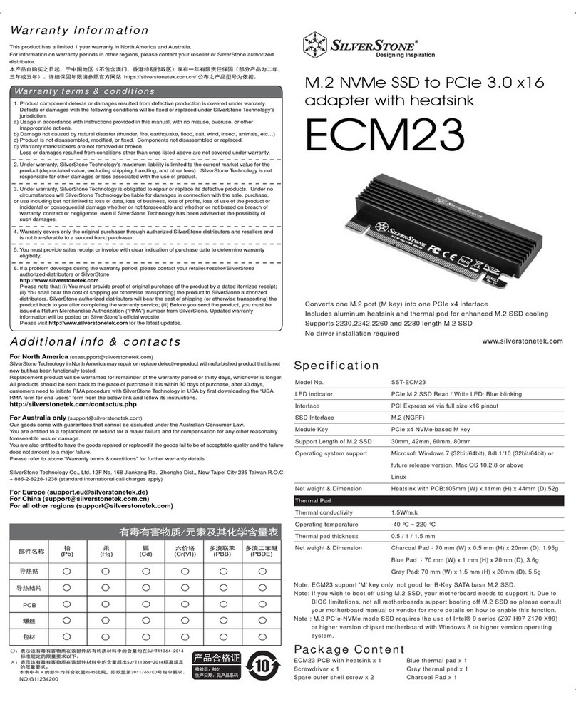
SPECIFICATION
Adapter Series
SST-AD60-DC
SST-AD120-DC
60W / 120W WATTS SWITCHING POWER SUPPLY
with AC adapter
1.1 VOLTAGE
1.2 CURRENT
AD60-DC
12Vdc / 6.0A max
AD120-DC
12Vdc / 12.0A max
1.3 POWER EFFICIENCY
90% at full load (LOAD REGULATION TEST TABLE LOAD 1、2)
1.0 INPUT:
MINIMUM NOMINAL MAXIMUM UNITS
11.4 12 12.6 Vdc
A. DC Board
P1

AD60-DC
AD120-DC
*1 When input voltage 11.4~11.8V regulation +5,-10
﹪
of +12Vdc
output.
*2 The continuous total output power is 60W max.
•Total combined +12V output load not exceed 5.0A
*3 Add 0.1uF and 10uF capacitors across output terminal during
ripple & noise test.
*4 LOAD REGULATION TEST TABLE:
2.0 OUTPUT:
Voltage +5V +3.3V +12V -12V +5Vsb
*
Max load 7.0A 7.0A 5.0A 0.1A 2.0A
*
Regulation
+5,-5
﹪﹪
+5,-5
﹪﹪
+5,-5
﹪﹪
+10,-10
﹪﹪
+5,-5
﹪﹪
*
Ripple&Noise 50mV 50mV 120mV 120mV 50mV
1
2
3
1
2
3
+5V +3.3V +12V -12V +5Vsb
LOAD1 (100
﹪
﹪
) 3.49A 3.49A 2.18A 0.04A 0.87A
LOAD2 (50
﹪
﹪
) 1.32A 1.32A 1.5A 0.0A 0.2A
LOAD3 1.50A 1.5A 1.0A 0.1A 2.0A
LOAD4 7.0A 2.5A 1.0A 0.1A 0.5A
LOAD5 3.0A 7.0A 1.5A 0.1A 0.5A
LOAD 6 0.0A 0.0A 5.0A 0.0A 0.0A
Voltage +5V +3.3V +12V -12V +5Vsb
*
Max load 12.0A 12.0A 10.0A 0.15A 3.0A
*
Regulation +5,-5
﹪
﹪
+5,-5
﹪
﹪
+5,-5
﹪
﹪
+10,-10
﹪
﹪
+5,-5
﹪
﹪
*
Ripple&Noise 50mV 50mV 120mV 120mV 50mV
P2

*1 When input voltage 11.4~11.8V regulation +5,-10
﹪
of +12Vdc
output.
*2 The continuous total output power is 60W max.
•Total combined +12V output load not exceed 5.0A
*3 Add 0.1uF and 10uF capacitors across output terminal during
ripple & noise test.
*4 LOAD REGULATION TEST TABLE:
TTL High/PS-OFF; TTL Low/PS-ON
VIL=0.8Vmax, IIL=-1.6mAmax @Vin=0.4V
VIH=2.0Vmin @Iin=-200uA, VIH=5.25Vmax @open ckt.
2.1 REMOTE ON/OFF
100-500 msec.
2.2 POWER GOOD DELAY
2000 msec max.At Nominal Line Full Load.
2.3 TURN-ON DELAY TIME
+/- 10% max with 20% load change on all outputs are 50% of the rated.
Load slew rated 1.0A/uS and capacitive load as below :
2.4 TRANSIENT OVERSHOOT
+5V +3.3V +12V -12V +5Vsb
LOAD1(100
﹪
﹪
) 5.0A 5.0A 5.8A 0.1A 1.5A
LOAD2(20
﹪
﹪
) 1.0A 1.0A 1.1A 0.0A 0.5A
LOAD3 12.0A 1.0A 0.1A 0.1A 3.0A
LOAD4 12.0A 2.5A 2.0A 0.1A 1.5A
LOAD5 3.0A 12.0A 5.0A 0.1A 1.0A
LOAD6 0.0A 0.0A 10.0A 0.0A 0.0A
+5V +3.3V +12V -12V +5Vsb
10000uF 10000uF 10000uF 330uF 10000uF
P3

20ms max at full load.
2.5 RISE TIME
Output voltage regulation +10,-10﹪
When OVP or short protection is triggered, the main outputs
will be latched off. The main outputs can be reset by cycling
the DC remote on/off.
2.6 DYNAMIC TEST
+5V output : 28A max.
+3.3V output : 28A max.
+12V output : 10A max.
3.1 OVER CURRENT PROTECTION
AD60-DC
+3.3V output 2.4 Vmax.
+5.0V output 3.7 Vmax.
+12.0V output 9.5 Vmax.
AD120-DC
+3.3V output 2.0 Vmax.
+5.0V output 3.3 Vmax.
+12.0V output 8.5 Vmax.
+3.3V output 4.1 Vmax.
+5.0V output 6.5 Vmax.
+12.0V output 14.4 Vmax.
3.2 UNDER VOLTAGE PROTECTION
3.3 OVER VOLTAGE PROTECTION
All output to GND.
3.4 SHORT PROTECTION
3.0 PROTECTION:
P4

4.1 OPERATING TEMP. 0 °C to +40 °C
4.2 STORAGE TEMP. -20 °C to +70 °C
4.3 OPERATING HUMIDITY 20% to 90%,non-condensing
4.4 STORAGE HUMIDITY 5% to 95%, non-condensing
4.5 OPERATING ALTITUDE 0 to 10,000feet
4.6 STORAGE ALTITUDE 0 to 50,000 feet
100K hrs minimum
AD60-DC
DC board dimension: WxLxH=148.5x30x25mm
AD120-DC
DC board dimension: WxLxH=160x45x25mm
5.0 MTBF at 25°C(demonstrated)
6.0 DIMENSIONS
4.0 ENVIRONMENT:
P5

60W
The total output power, under steady state conditions, shall not
exceed 60 W.
2.0 Output requirement
Output power
Output voltage and current
Table 2 - Output Voltage and Current
Under any combination of line and load variation and
environmental conditions, all outputs shall remain within
tolerance as defined in Table 2. Output voltage(s) shall be
measured at the load side of output connector.
Output
Voltage
Voltage Range Current Range
Lower
Limit Upper
Limit Minimum
Load Full rated
load PK Load
+12.0V 11.40V 12.60V 0.0A 5.0A --
P6
Power supply shall operate within specification from 90 to 264Vrms or provide automatic
switching in two ranges. The table below shows common input voltage range.
Maximum steady state input current shall not exceed 1.7 A for any line voltage specified
in Input voltage range define.
1.0 Input voltage range
Input current
B. AC adapter
Input Range Minimum Nominal Maximum Unit
90 100 -240 264 Vac, rms

3.0 Ptotection
The power supply shall provide with over voltage protection such
that under any single component failure.
The power supply provides output over voltage protected in latch
off by zener diode, and no damage to customer device.
60W
The power supply shall be protected when operating any output in
overload condition. The power supply shall be shut down and no
any damage when the over current condition occurs on the output,
and It will be auto-recovered when the failure is removed.
Over voltage protection
Over current protection
P7
120W
Unit total output power, under steady state conditions, shall not
exceed 120 W .
Output power
Under any combination of line and load variation and
environmental conditions, all outputs shall remain within
tolerance defined in Table 2. Output voltage(s) shall be
measured at the load side of output connector.
Output voltage and current
Table 2 - Output Voltage and Current
Output
Voltage
Voltage Range Current Range
Lower
Limit Upper
Limit Minimum
Load
Full
rated
load Peak Load
1 +12V 11.4V 12.6V 0A 10A 13A@10s
(115/230VAC)

Short circuit protection
4.0 AC adapter external dimension
Power supply shall have self-limiting protection to protect against
short circuit or overload conditions. No damage to the supply
shall result from a continuous or intermittent short circuit condition.
60W
Dimension without cable: 116mmX52.4mmX31.3mm
Cable length:1200mm±20mm
120W
Dimension without cable: 168mmX71mmX37.5mm
Cable length:1200mm±20mm
P8
60W
During turn on or turn off, the output overshoot shall not exceed
nominal output voltage by more than 5% , and output shall not
change its polarity with respect to its return line.
120W
During turn on, turn off condition, the output overshoot shall not
exceed nominal voltage by more than 10% , and output shall not
change its polarity with respect to its return line.
120W
Over current protection shall be operated within specify
14.5A (min) ~ 20A (Max) , defined in section 2.3.1 at 100~240Vac
line input or temperature conditions.
Overshoot and undershoot
Table 4 –Over current protection
Output
Voltage
Over current protection Test condition
Lower Limit Upper Limit Input
voltage:100Vac
60Hz or 240Vac
50Hz.
+12.0V 5.80A 9.00A
1.
Installation
Step 1: Place the 120W DC to DC power board in the
chassis and secure it with screws. (Put the transparent
Mylar sheet at the back)
Шаг 1: Поместите плату питания 120 Вт
DC - DC вкорпус изакрепите её винтами.
(Положите прозрачный майларовый лист сзади)
Schritt 1: Platzieren Sie die 120-W-Gleichspannung-zu-
Gleichspannung-Netzplatine im Gehäuse und fixieren
Sie sie mit Schrauben. (Platzieren Sie das transparente
Mylar-Blatt an der Rückseite)
步驟1: 請將120 W DC to DC 電源板鎖固在機殼內
(透明麥拉片請放在後面)
Paso 1: Coloque la placa de corriente CC a CC de 120W
en el chasis y fíjela con tornillos. (Coloque la hoja Mylar
transparente en la parte trasera)
ステップ1:120WDC〜DC電源ボードをケースに
設置してネジ止めします。(透明なマイラーシートを
背面に設置)
Étape 1 : Placez la carte d’alimentation CC vers CC de
120 W dans le châssis et fixez-la avec des vis. (Mettez
la feuille transparente en Mylar à l’arrière)
步骤1:请将120 W DC to DC 电源板锁固在机壳内
(透明麦拉片请放在后面)
Fase 1: Collocare la scheda di alimentazione da 120 W
CC-CC nello chassis e fissarla con le viti. (Posizionare il
foglio in mylar trasparente sul retro)
스텝 1: 120W DC to DC 파워 보드를 섀시에 놓고,
볼트로 고정을 합니다. (후면에 투명한 마일라
시트를 넣습니다)
ขั้นที่ 1: ใส่เพาเวอร์บอร์ด DC เป็น DC 120 วัตต์ ลงในเคส
และยึดด้วยสกรูให้แน่น (ใส่แผ่นไมลาร์ใสที่ด้านหลัง)
ไทย
P9

2.
Installation
Step 2: Connect 24pin to 20+4pin cable to the 120 W
DC to DC power board. (Connect 20+4pin cable to the
motherboard, 24pin cable to the DC board)
Шаг 2: Подключите кабель 24pin - 20+4pin к
плате 120 Вт DC - DC. (Подключите кабель
20 + 4pin кматеринской плате, кабель 24pin к
плате DC)
Schritt 2: Verbinden Sie das 24-Pin-zu-20+4-Pin-Kabel
mit der 120-W-Gleichspannung-zu-Gleichspannung-
Netzplatine. (Verbinden Sie das 20+4-Pin-Kabel mit
dem Motherboard und das 24-Pin-Kabel mit der
Gleichspannungsplatine)
步驟2:請將24pin to 20+4pin 線材插入120W
DC to DC 電源板(20+4pin接MB,24pin接DC板)
Paso 2: Conecte el cable de 24pines a 20+4pines a la
placa de corriente CC a CC de 120W. (Conecte el cable
20+4pines a la placa base y el cable de 24pines a la
placa CC)
ステップ2:24ピン〜20+4ピンケーブルを120W
DC〜DC電源ボードに接続します。(20+4
ピンケーブルをマザーボードに、24ピンケーブルを
DCボードに接続)
Étape 2 : Raccordez le câble 24 broches vers 20+4
broches à la carte d’alimentation CC vers CC de 120 W.
(Raccordez le câble 20+4 broches à la carte mère,
le câble 24 broches à la carte CC)
步骤2:请将24pin to 20+4pin 线材插入120W
DC to DC 电源板(20+4pin接MB,24pin接DC板)
Fase 2: Collegare il cavo da 24 pin a 20+4 pin alla scheda
di alimentazione da 120 W CC-CC. (Collegare il cavo a
20+4 pin alla scheda madre, il cavo a 24 pin alla
scheda CC)
스텝 2: 24핀 to 20+4핀 케이블을 120W DC to DC
파워 보드에 연결합니다. (20+4핀 케이블은
마더보드에, 24핀 케이블은 DC 보드에 연결합니다)
ขั้นที่ 2: เชื่อมต่อสายเคเบิล 24 พินเป็น 20+4 พิน
เข้ากับเพาเวอร์บอร์ด DC เป็น DC 120 วัตต์ (เชื่อมต่อสายเคเบิล
20+4 พิน เข้ากับเมนบอร์ด, สายเคเบิล 24 พินเข้ากับบอร์ด DC)
ไทย
P10

3.
Installation
Step 3: Connect CPU connector, 20+4pin connector,
and other cables to the device.
Шаг 3: Подключите коннектор питания
процессора, коннектор 20 + 4pin идругие
кабели кустройству.
Schritt 3: Verbinden Sie den CPU-Anschluss, den
20+4-Pin-Anschluss und andere Kabel mit dem Gerät.
步驟3:將CPU,20+4pin及其他相關線材連接到裝置
Paso 3: Enchufe el conector CPU, conector 20+4pines
y otros cables al dispositivo.
ステップ3:CPUコネクタ、20+4ピンコネクタ、その他
ケーブルをデバイスに接続します。
Étape 3 : Raccordez le connecteur du processeur, le
connecteur 20+4 broches et les autres câbles au
dispositif.
步骤3:将CPU,20+4pin及其他相关线材连接到装置
Fase 3: Collegare il connettore della CPU, il connettore
a 20+4 pin e altri cavi al dispositivo.
스텝 3: CPU 커넥터, 20+4핀 커넥터 그리고
기타 케이블들을 장치에 연결합니다.
ขั้นที่ 3: เชื่อมต่อขั้วต่อ CPU, ขั้วต่อ 20+4 พิน
และสายเคเบิลอื่น ๆเข้ากับอุปกรณ์
ไทย
P11

4.
Installation
Step 4: Connect the internal power cord to the
DC to DC board, and secure the DC jack connector
in the chassis with screws.
Шаг 4: Подключите внутренний кабель питания
кплате DC - DC, изакрепите коннектор DC в
корпусе винтами.
Schritt 4: Verbinden Sie das interne Stromkabel mit der
Gleichspannung-zu-Gleichspannung-Platine und sichern
Sie den Gleichspannungsanschluss im Gehäuse mit
Schrauben.
步驟4:將內部電源線連接直DC to DC 板並將
DC jack 的接頭鎖固在機殼上
Paso 4: Conecte el cable de corriente interno a la placa
CC a CC y fije el conector CC al chasis con tornillos.
ステップ4:内部電源コードをDC〜DCボードに接続し、
ケースのDCジャックコネクタをネジ止めします。
Étape 4 : Raccordez le cordon d’alimentation interne à
la carte CC vers CC et fixez le connecteur jack CC
dans le châssis avec des vis.
步骤4:将内部电源线连接直DC to DC 板并将
DC jack 的接头锁固在机壳上
Fase 4: Collegare il cavo di alimentazione interno alla
scheda CC-CC e fissare il connettore della presa CC
nello chassis con le viti.
스텝 4: DC to DC 보드에 내부 전원 코드를
연결하고, DC 잭 커넥터를 섀시에 볼트로
고정합니다.
ขั้นที่ 4: เชื่อมต่อสายไฟภายในเข้ากับบอร์ด DC เป็น DC,
และยึดขั้วต่อแจ็ค DC ในเคสด้วยสกรู ์
ไทย
P12

P13
5.
Installation
Step 5: Make sure every cable is connected. Шаг 5: Убедитесь, что все кабели подключены.
Schritt 5: Stellen Sie sicher, dass alle Kabel
angeschlossen sind.
步驟5:確認所有線材均已經連接完成
Paso 5: Asegúrese de que cada cable está conectado. ステップ5:ケーブル全部が接続されたことを
確認します。
Étape 5 : Assurez-vous que tous les câbles sont raccordés.. 步骤5:确认所有线材均已经连接完成
Fase 5: Assicurarsi che tutti i cavi siano collegati. 스텝 5: 모든 케이블을 연결되었는지 확인합니다.
ขั้นที่ 5: ตรวจดูให้แน่ใจว่าเชื่อมต่อสายเคเบิลทั้งหมดแล้ว์
์
ไทย

P14
6.
Step 6: Connect the AC adapter to the DC cable to
complete the installation.
Шаг 6: Подключите адаптер AC ккабелю DC,
чтобы завершить установку.
Schritt 6: Verbinden Sie zum Abschließen der Installation
das Netzteil mit dem Gleichspannungskabel.
步驟6:將AC adapter連接至DC線完成安裝
Paso 6: Conecte el adaptador de CA al cable CC para
completar la instalación.
ステップ6:ACアダプタをDCケーブルに接続すると、
インストール完了です。
Étape 6 : Raccordez l’adaptateur CA au câble CC pour
terminer l’installation.
步骤6:将AC adapter连接至DC线完成安装
Fase 6: Collegare l'adattatore CA al cavo CC per
completare l'installazione.
스텝 6: AC 어댑터를 DC 케이블에 연결하고 설치를
마무리 합니다.
ขั้นที่ 6: เชื่อมต่ออะแดปเตอร์ AC เข้ากับสายเคเบิล DC
เพื่อทำการติดตั้งให้สมบูรณ์
์
ไทย
Installation

Warranty Information
This product has a limited 1 year warranty in North America andAustralia.
For information on warranty periods in other regions, please contact your reseller or SilverStone authorized distributor.
本产品自购买之日起,于中国地区(不包含澳门,香港特别行政区)享有一年有限责任保固(部分产品为二年,三年或五年)。
详细保固年限请参照官方网站 https://silverstonetek.com.cn/ 公布之产品型号为依据。
1. Product component defects or damages resulted from defective production is covered under warranty.
Defects or damages with the following conditions will be fixed or replaced under SilverStone Technology’s jurisdiction.
a) Usage in accordance with instructions provided in this manual, with no misuse, overuse, or other inappropriate actions.
b) Damage not caused by natural disaster (thunder, fire, earthquake, flood, salt, wind, insect, animals, etc…)
c) Product is not disassembled, modified, or fixed. Components not disassembled or replaced.
d) Warranty mark/stickers are not removed or broken.
Loss or damages resulted from conditions other than ones listed above are not covered under warranty.
2. Under warranty, SilverStone Technology’s maximum liability is limited to the current market value for the product (depreciated value, excluding
shipping, handling, and other fees). SilverStone Technology is not responsible for other damages or loss associated with the use of product.
3. Under warranty, SilverStone Technology is obligated to repair or replace its defective products. Under no circumstances will SilverStone
Technology be liable for damages in connection with the sale, purchase, or use including but not limited to loss of data, loss of business, loss of
profits, loss of use of the product or incidental or consequential damage whether or not foreseeable and whether or not based on breach of warranty,
contract or negligence, even if SilverStone Technology has been advised of the possibility of such damages.
4. Warranty covers only the original purchaser through authorized SilverStone distributors and resellers and is not transferable to a second hand
purchaser.
5. You must provide sales receipt or invoice with clear indication of purchase date to determine warranty eligibility.
6. If a problem develops during the warranty period, please contact your retailer/reseller/SilverStone authorized distributors or SilverStone
http://www.silverstonetek.com.
Please note that: (i) You must provide proof of original purchase of the product by a dated itemized receipt; (ii) You shall bear the cost of shipping
(or otherwise transporting) the product to SilverStone authorized distributors. SilverStone authorized distributors will bear the cost of shipping
(or otherwise transporting) the product back to you after completing the warranty service; (iii) Before you send the product, you must be issued a
Return Merchandise Authorization (“RMA”) number from SilverStone. Updated warranty information will be posted on SilverStone’s official website.
Please visit http://www.silverstonetek.com for the latest updates.
Warranty terms & conditions
Additional info & contacts
SilverStone Technology in North America may repair or replace defective product with refurbished product that is not new but has been functionally tested.
Replacement product will be warranted for remainder of the warranty period or thirty days, whichever is longer. All products should be sent
back to the place of purchase if it is within 30 days of purchase, after 30 days, customers need to initiate RMA procedure with SilverStone Technology
in USA by first downloading the “USARMAform for end-users” form from the below link and follow its instructions.
http://silverstonetek.com/contactus.php
Our goods come with guarantees that cannot be excluded under the Australian Consumer Law.
You are entitled to a replacement or refund for a major failure and for compensation for any other reasonably foreseeable loss or damage.
You are also entitled to have the goods repaired or replaced if the goods fail to be of acceptable quality and the failure does not amount to a major failure.
Please refer to above “Warranty terms & conditions” for further warranty details.
SilverStone Technology Co., Ltd. 12F No. 168 Jiankang Rd., Zhonghe Dist., New Taipei City 235 Taiwan R.O.C. + 886-2-8228-1238
(standard international call charges apply)
P15

This device complies with Part 15 of the FCC Rules.
Operation is subject to the following two conditions:
(1) this device may not cause harmful interference, and
(2) this device must accept any interference received, including interference
that may cause undesired operation.
Please refer to SilverStone website for latest specifications updates.
The power supply is only suitable for Information Technology & Audio/Video equipment.
※付属の電源コードは当該製品専用です。他の機器に使用しないでください。
P16


G11240920
This manual suits for next models
1
Table of contents
Other SilverStone Adapter manuals

SilverStone
SilverStone SDP11 User manual

SilverStone
SilverStone SST-ECM23 User manual

SilverStone
SilverStone ECM20 User manual

SilverStone
SilverStone SST-EC02 User manual

SilverStone
SilverStone ECM24 User manual

SilverStone
SilverStone FP57 User manual

SilverStone
SilverStone MUA01 User manual

SilverStone
SilverStone SDP12 User manual

SilverStone
SilverStone FP510 User manual

SilverStone
SilverStone ECD01 User manual