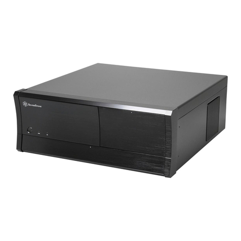
SilverStone Fortress SFTZ01-E User manual

Fortress Series
Premium slim form factor case
with superior thermodynamics and construction
FTZ01-E

The following manual and guides were carefully prepared by the SilverStone engineering team to
help you maximize the potential of your SilverStone product. Please keep this manual for future
reference when upgrading or performing maintenance on your system.Acopy of this manual can also
be downloaded from our website at:
Installation and system optimization guide:
Product Overview
Specification
Disassemble Chart
Exterior Overview
Installation Guide
Connector Definition
Componet Size Limitations
Optimal Thermal Performance Layout
Maintenance And Upgrade
Protect Your Computer
Q&A
Warranty Information
P.1
P.1
P.2
P.3
P.4
P.13
P.16
P.21
P.25
P.27
P.28
P.29

Product Overview
Specification
Model No.
Material
Motherboard
Drive Bay
Cooling System
Expansion Slot
Front I/O Port
Power Supply
Expansion Card
Limitation of CPU cooler
Limitation of PSU
Net weight
Dimension
Extra
* 2.5" drive on center bracket may be difficult or impossible to install due to power supply cable interference
SST-FTZ01B-E (black), SST-FTZ01S-E (silver)
Aluminum unibody frame, steel chassis
Mini-DTX, Mini-ITX
External
Internal
Top
Bottom
2
USB 3.0 x 2,Audio x 1, MIC x 1
PS2 (ATX) Optional
Support graphics card up to 13" (330mm), width restriction – 5.88" (149mm)
83mm
150mm*
4.49kg
376mm (W) x 107mm (H) x 351mm (D), 14 Liters, 14.8" (W) x 4.21" (H) x 13.82" (D), 14 Liters
Support Kensington locks
--
2.5" x 4
1 x 120mm fan, 1500rpm 18dBA
1 x 120mm fan, 1500rpm 18dBA, 1 x 120mm fan slot
Fortress Series FTZ01-E
Introduction
1
The Fortress FTZ01-E was created to cater to enthusiasts with affinity
for all metal design in slim form factor cases. It can accommodate
the biggest consumer 13" graphics card on the market with superb air
cooling performance and offers compatibility withATX (PS2) power
supplies. Designed for use in either vertical or horizontal orientation,
the FTZ01-E can be placed comfortably in any space-constrained
environment that requires a powerful PC. For those looking to build
a premium, all-metal slim form factor PC, there is another excellent
choice in the FTZ01-E.
Special Features
Classic exterior built from aluminum unibody frame
Support cards up to 13 inches (330mm) to fit most high-end GPUs for compute power far exceeding consoles
Mini-ITX motherboard &ATX PSU compatible for wide array of building possibilities
Maximum performance in slim form factor with support forAIO liquid cooling
Positive air pressure design for excellent cooling/quietness and dust-prevention
Fits in nearly any environment with horizontal or vertical orientation

Disassemble Chart
Fortress Series FTZ01-E
2
Picture Purpose NO.
4
4
1
1
2
8
8
2
2
14
12
1
2
1
Vertical foot stands
Rubber foot
For vertical use
For horizontal use
VGAcard bracket - TOP
VGAcard bracket - Bottom
SCREWA4 X 15 - M3 X 4
ITEM
VGAcard bracket foam pad
SCREW B 4 X 15 - 632 X 4
SCREW C 632 X 8
SCREW D M2 X 2
SCREW E 632 X 5
SCREW F M3 X 4
Zipper Bag
Manual
SCREW - PAN - 4 X 4.8H - 6 - 32 X 3.4 - NI
Secure VGAsupport bracket
Secure optical drive
Securemotherboard,PSU, 3.5"HDDandwatercooling pump
Secure 2.5" SSD/HDD
Secure radiator cooling fan
2.5" HDD X1
2.5" HDD X2
TOPCOVER
FAN FILTER X1
12015 FAN X1
MINI-ITX (OPTION)
POWER CAGE
ATX PSU (OPTION)
FAN FILTER X2
12015 FAN X1
USB 3.0 + SPK + MIC
POWER BUTTON
POWER LED
HDD LED
RESETBUTTON
HDD CAGE
2.5" HDD X1

Exterior Overview
TOP
FRONT
BACK
RIGHT SIDELEFT SIDE
Fortress Series FTZ01-E
3

have all components collected
check that all components do not have compatibility problems with each other or with the case
if possible, assemble the components outside the case first to make sure they are working
keep the motherboard manual ready for reference during installation
prepare a Philips screwdriver.
Installation Chart
Fortress Series FTZ01-E
4
1
2
3
4
5
Before you begin, please make sure that you
01
02
Lösen Sie die beiden Schrauben von
der Rückseite des Gehäuses, entfernen
Sie dann die obere Abdeckung
Dévissez les deux vis à l'arrière du
châssis puis enlevez le couvercle
supérieur
Afloje dos tornillos de la parte posterior
del chasis para retirar la cubierta
superior
Allentare le due viti sul lato posteriore
del telaio e poi rimuovere il coperchio
superiore
Unscrew the screws from the rear
of the chassis then remove the top
cover
Ослабьте два винта на задней
панели корпуса иснимите
верхнюю крышку
섀시 후면에 있는 두 개의 나사를푼
다음 상단 커버를 분리합니다
鬆開上蓋螺絲,取下上蓋
松开上盖螺丝,取下上盖
ケース後部のネジ2本をゆるめて
からトップカバーを取り外します
Lösen Sie die Schrauben von der
Grafikkartenhalterung und entfernen
sie anschließend
Dévissez les vis du support de la
carte graphique puis enlevez-la
Desenrosque los tornillos del bracket
de soporte de la tarjeta gráfica y luego
retírela
Svitare le viti dalla staffa di support
della scheda video quindi rimuoverla
Unscrew the screws from the graphics
card support bracket then remove it
Отверните винты кронштейна
крепления графической карты
иснимите его
그래픽 카드 지지 브래킷에서 나사를
풀어 브래킷을 분리합니다
鬆開顯示卡架的螺絲,取下顯示卡架
松开显示卡架的螺丝,取下显卡架
グラフィックスカード・サポート
ブラケットのネジを外して取り外
します

Installation Chart
Fortress Series FTZ01-E
5
03
04
Lösen Sie zum Abnehmen die Schraube
an der Netzteilhalterung
Dévissez les vis du support du bloc
d'alimentation pour le retirer
Afloje el tornillo de la carcasa de la
FA para retirarla
Allentare la vite sulla staffa PSU per
rimuoverlo
Unscrew the screws from PSU bracket
then remove it
Отвинтите винт кронштейна
блока питания иизвлеките его
PSU 케이스의 나사를 풀어 케이스를
분리합니다
鬆開電源架的螺絲,取下電源架
松开电源架的螺丝,取下电源架
PSUケージのネジを緩めて取り外
します
Falls Sie eine 2,5-Zoll-Festplatte/SSD
in der mittleren Klammer montieren
möchten, empfehlen wir, sie in diesem
Schritt zu entfernen
Si vous voulez installer un DD/SSD
de 2,5" sur la partie centrale, nous
vous recommandons de l'enlever lors
de cette étape
Si quiere montar un HDD/SSD de 2,5"
en la abrazadera central, le
recomendamos que la retire en este
paso
Se si vuole montare un HDD/SSD 2,5"
sul supporto centrale, si consiglia di
rimuoverlo a questo punto
If you want to mount a 2.5" HDD/SSD
on the center brace, we recommend
you to remove it in this step
Если вы собираетесь установить
2,5-дюймовый жесткий или
твердотельный диск на центральном
кронштейнe, мы рекомендуем
извлечь его на этом шаге
중앙 죔쇠에 2.5" HDD/SSD를 장착
하려는 경우 이 단계에서 이를
분리할 것을 권장합니다
如果有需要在中央的支架上安裝
2.5"硬碟,建議你這時取下來安裝
如果有需要在中央的支架上安装
2.5"硬盘,建议你这时取下来安装
2.5" HDD/SSDをセンターブレ-ス
に取り付ける場合には、この段階
で取り外すようお勧めいたします
1
2

Installation Chart
Fortress Series FTZ01-E
6
06
Setzen Sie das mit Ihrem Motherboard
gelieferte I/O-Blech in die Aussparungen
an der Rückseite des Gehäuses ein,
installieren Sie anschließend das
Insérez la plaque d'E/S inclus avec
votre carte mère, puis installez la
carte mère dans le boîtier
Inserte el protector de E/S incluido
en su placa base, luego instale la
placa base en la carcasa
Installare la mascherina I/O inclusa
con la scheda madre, quindi installare
la mainboard nel case
Insert the I/O shield included with your
motherboard then install the
motherboard into the chassis
Установите заглушку для разъёмов
задней панели материнской платы,
прилагаемую кматеринской плате,
затем установите материнскую
плату вкорпус
메인보드와 같이 동봉된 I/O Shield
를 삽입한 후, 메인보드를 케이스
에설치합 니다
將I/O彈片裝上機殼,裝上主機板
将I/O弹片装上机箱,装上主板
お持ちのマザーボードに付属のI/O
シ ールドを挿入してから、ケース
の中 にマザーボードを取り付け
ます
05
Falls Sie den SilverStone NT06-PRO
oder einen vergleichbarenCPU-Kühler
verwenden möchten, entfernen Sie
bitte den 120-mm-Lüfter an der oberen
Blende und bringen ihn an den unteren
Belüftungsöffnungen in der Nähe des
Grafikkartenbereichs an
Si vous souhaitez utiliser SilverStone
NT06-PRO ou un autre refroidisseur
de CPU similaire, veuillez déplacer
le ventilateur de 120mm du panneau
supérieur sur la sortie inférieure près
de la zone de la carte graphique
Si quiere usar un SilverStone NT06-PRO
u otro disipador para CPU similar, por
favor recoloque el ventilador de 120mm
del panel frontal en el respiradero inferior
cerca de la zona de la tarjeta gráfica
Se si vuole utilizzare dispersore di
calore CPU SilverStone NT06-PRO
o simile, riposizionare la ventola da
120 mm sulla presa d’aria inferior
vicino alla zona della scheda video
If you want to use SilverStone
NT06-PRO or other similar CPU
cooler, please relocate the top
panel 120mm fan to the bottom
vent near the graphics card area
Если вы собираетесь использовать
SilverStone NT06-PRO или
аналогичную систему охлаждения
процессора, переставьте 120-мм
вентилятор сверхней панели на
нижнюю панель свентиляционными
отверстиями рядом сместом
установки графической карты
SilverStone NT06-PRO 또는 기타 이와
유사한 CPU 쿨러를 사용하려는 경우
상단 패널의 120mm 팬을 그래픽 카드
근처에 있는 하단 통풍구로 위치를
바꾸십시오
原廠預設安裝兩顆120mm風扇,如果
你有使用NT06-PRO請將上蓋的風扇
取下,安裝到顯示卡區域的後方
原厂预设安装两颗120mm风扇,如果
你有使用NT06-PRO请将上盖的风扇
取下,安装到显示卡区域的后方
SilverStone NT06-PROまたはその
他同様のCPUクーラーを使用される
場合は、トップパネルの120mmファ
ンをグラフィックスカード付近の
底部換気口付近に移動させます
1
2
Installation Chart
Fortress Series FTZ01-E
7
07
08
Wir empfehlen, an diesem Punkt alle
erforderlichen Kabel, einschließlich
der SATA-Kabel, am Motherboard
anzuschließen
Nous vous recommandons à ce point
de brancher tous les cables nécessaires,
y compris les cables SATA, sur la
carte mère
Le recomendamos que en este punto
conecte todos los cables necesarios,
incluidos los cables SATA a la placa
base
Consigliamo a questo punto di
collegare alla scheda madre tutti i
cavi necessari compresi i cavi SATA
We recommend at this point connecting
all the necessary cables including the
SATA cables to the motherboard
На этом этапе мы рекомендуем
подключить ксистемной плате
все необходимые кабели, включая
кабели SATA
이 시점에서 SATA 케이블을
포함하여 필요한 모든 케이블을
메인보드에 연결할 것을 권장합니다
將機殼所有線材連接上主機板,
SATA線材建議你這時可以先插上
主機板
将机箱所有线材连接上主板,
SATA线材建议你这时可以先插上
主板
この時点で、SATAケーブルを含む
必要なケーブル全てをマザーボー
ドに接続しておくことをお勧めい
たします
Befestigen Sie Netzteil in der
Netzteilhalterung
Attachez le bloc d'alimentation sur
le support du bloc d' alimentation
Fije la fuente de alimentación el bracket
de la fuente de alimentación
Befestigen Sie Netzteil in der Netztei
lhalterung
Secure the PSU into the PSU bracket Закрепите блок питания
кронштейне крепления блока
питания
PSU를 PSU 브래킷에 고정합니다
將電源安裝上電源架
将电源安装上电源架
PSUをPSUブラケットに固定します
Wir emp
f
ehlen, a
n
e
r
f
orderlichen K
a
der
S
ATA-Kabel
anzu
schl
ieße
n
Nous vous recom
m
de brancher tous le
s
y
compris les c
a
ca
rt
e
m
è
r
e
Le recomendamo
s
c
one
cte
todo
s lo
s
incluidos los cabl
e
base
C
onsi
g
liamo a
c
oll
egar
e alla s
c
cavi necessari co
y
S
ATA cables to t
h

Installation Chart
Fortress Series FTZ01-E
8
10
Stecken Sie die Netzteilhalterung in
ihre ursprüngliche Position und
befestigen sie mit Schrauben
Insérez le support du bloc
d'alimentation dans sa position
d'origine et attachez-le avec des vis
Inserte el bracket de la FA en su
posición original y fíjelo con tornillos
Inserire la staffa della PSU nella sua
posizione originaria e fissarla con le
viti
Insert the PSU bracket into its original
position and secure with screws
Установите кронштейн блока
питания висходное положение
изакрепите винтами
PSU 브래킷을 원래의 위치에
삽입하고 나사로 고정합니다
將電源架推定位,鎖上螺絲
将电源架推定位,锁上螺丝
PSUブラケットを元の場所に収め
て からネジで固定します
09
Bringen Sie die Netzteilhalterung im
oberen Bereich des Gehäuses an;
schließen Sie dann das Netzkabel
am Netzteil an
Placez le support du bloc d'alimentation
sur le dessus du châssis puis branchez
le cordon d'alimentation sur le bloc
d'alimentation
Sitúe el bracket de la FA en la parte
superior del chasis y luego conecte
el cable de potencia a la FA
Collocare la staffa PSU sulla parte
superiore del telaio quindi collegare
il cavo di alimentazione alla PSU
Place the PSU bracket on top of the
chassis then connect the power cord
to the PSU
Установите кронштейн блока
питания вверхней части корпуса
иподключите кабель питания к
блоку питания
PSU 브래킷을 섀시 상단에 위치시킨
후 전원 코드를 PSU에 연결합니다
將電源架放上機殼,接上電源線
将电源架放上机箱,接上电源线
PSUブラケットをケース上部に設
置 し、電源コードをPSUに接続
します

Installation Chart
Fortress Series FTZ01-E
9
11
12
Entfernen Sie die Abdeckung des
Erweiterungssteckplatzes und
installieren die Grafikkarte in der
Grafikkartenhalterung
Retirez le couvercle de la fente
d'expansion et installez la carte
graphique dans le support de la carte
graphique
Retire la cubierta del zócalo de
expansion e instale la tarjeta gráfica
en el bracket de soporte de la tarjeta
gráfica
Togliere il coperchio dell’alloggio
d’espansione ed installare la scheda
video sulla staffa di supporto della
scheda video
Remove expansion slot cover and
install graphics card into the graphics
card support bracket
Снимите крышку слота расширения
иустановите графическую карту
на кронштейн крепления
графической карты
확장 슬롯 커버를 벗기고 그래픽
카드를 그래픽 카드 지지 브래킷에
설치합니다
拆下顯示卡卡條,把顯示卡安裝上
顯示卡架
拆下显示卡卡条,把显示卡安装上
显示卡架
拡張スロットカバーを取り外して、
グラフィ ックスカード・サポー
トブラケットにグラフィックスカ
ードを設置します
Je nach Design Ihrer Grafikkarten
können Sie die Grafikkartenhalterung
zur Unterstützung Ihrer Karte in einer
geeigneten Position installieren und
anpassen. Befestigen Sie die mitgelieferten
Gummipolster entsprechend der Höhe
der Grafikkartenrückseite; eins (bei
3 mm dicker Rückplatte) oder zwei
(bei Komponenten ohne Rückseite)
Selon le type de votre carte graphique,
installez et ajustez le crochet de carte
graphique à une bonne position pour
supporter votre carte. Utilisez les
rembourrages en caoutchouc inclus
selon la hauteur de l'arrière de la carte
graphique, un (pour plaque arrière de
3mm d'épaisseur) ou deux (pour les
composants sans plaque arrière)
Dependiendo del diseño de su tarjeta
gráfica, instale y ajuste el soporte de
la tarjeta gráfica en una posición
apropiada para acomodarse a su tarjeta.
Adhiera el acolchado de goma incluido
según la altura de la parte trasera de
la tarjeta gráfica, uno (para una placa
trasera de 3mm de grosor) o dos
(cuando no existan componentes de
la parte trasera)
Ina base al design delle schede video,
installare e regolare il supporto della
scheda video sulla posizione adeguata
per supportare la scheda. Fare aderire
l’imbottitura di gomma fornita in
dotazione in base all'altezza del lato
posterior della scheda video, una (per
backplate di spessore 3 mm) o due
(per nessun component backside)
Depending on the design of your
graphics cards, install and adjust the
graphics card holder to a proper
position to support your card. Adhere
included rubber padding according to
the height of graphics card’s backside,
one (for 3mm thick backplate) or two
(for no backside components)
Взависимости от конструкции
графической карты установите
иотрегулируйте фиксатор
кронштейна графической карты
внужном положении. Установите
резиновую прокладку всоответствии с
высотой тыльной стороны
графической карты, одну (для
опорной пластины толщиной 3 мм)
или две (если на опорной пластине
отсутствуют компоненты)
그래픽 카드의 디자인에 따라 그래픽
카드를 지지하기에 올바른 위치에
그래픽 카드 홀더를 설치하고
조정하십시오. 그래픽 카드 뒷면의
높이에 따라 제공된 고무 패드를
하나(뒷판 두 께가 3mm인 경우)
또는 두 개(브래킷 부품이 없는
경우)를 부착하십시오
視顯示卡形狀而定,選一個適當的
位置將顯示卡托架安裝上顯示卡架,
請視顯示卡背面的元件高度或背板
來判斷,在拖架上黏貼1個(背板3mm)
或2個(背面無元件)橡膠墊片
视显示卡形状而定,选一个适当的
位置将显示卡托架安装上显示卡架,
请视显示卡背面的组件高度或背板
来判断,在拖架上黏贴1个(背板3mm)
或2个(背面无组件)橡胶垫片
ご使用のグラフィックスカードの
デザインに 従い、カードをサポ
ートする適当な位置にグ ラフィ
ックスカード・ホルダーをインス
トー ル、調整します。グラフィ
ックスカードの後 部の高さに合
わせて、付属のゴムパッドを1枚
(厚さ3mmのバックプレート用)
または2枚(後部コンポーネント
なしの場合)貼付します
Included Foam Pad

Installation Chart
Fortress Series FTZ01-E
10
14
Installieren Sie die Grafikkartenhalterung
im Gehäuse und schließen das
Netzkabel wie erforderlich an die
Grafikkarte an
Installez le support de la carte
graphique dans le châssis et branchez
le cordon d'alimentation sur la carte
graphique si nécessaire
Instale el bracket de soporte de la
tarjeta gráfica en el chasis y conecte
el cable de potencia a la tarjeta
gráfica si es necesario
Installare la staffa di supporto della
scheda video nel telaio e collegare il
cavo di alimentazione alla scheda
video, se necessario
Install graphics card support bracket
into the chassis and connect the power
cord to the graphics card if needed
Установите крепежный кронштейн
графической карты вкорпус и
при необходимости подключите
кабель питания кграфической
карты
그래픽 카드 지지 브래킷을 섀시에
설치하고 필요한 경우 전원 코드를
그래픽 카드에 연결합니다
將顯示卡架裝上機殼,如果顯示卡
有電源線要連接,請先接好
将显示卡架装上机箱,如果显示卡
有电源线要连接,请先接好
ケースにグラフィックスカード・
サポートブラケットを取り付け、
必要ならば電源コードをグラフィ
ックスカードに接続します
13
Installieren Sie eine 2,5-Zoll-Festplatte
/SSD an der Grafikkartenhalterung
Installez le lecteur de DD/SSD de
2,5" sur le support de la carte
graphique
Instalar un 2,5" HDD/SSD en el
bracket de soporte de la tarjeta
gráfica
Installare l’unità HDD/SSD 2,5"
sulla staffa di supporto della
scheda video
Install 2.5" HDD/SSD onto the
graphics card support bracket
Установите 2,5-дюймовый
жесткий или твердотельный
диск через слот на крепежный
кронштейн графической карты
2.5" HDD/SSD 방식 를 그래픽
카드 지지 브래킷에 설치합니다
將2.5"硬碟安裝上顯示卡架
将2.5"硬盘安装上显示卡架
2.5" HDD/SSDをグラフ・サポート
ブラケット上にインストールしま
す

Installation Chart
Fortress Series FTZ01-E
11
15
16
Achten Sie darauf, dass sämtliche
Kabel richtig angeschlossen sind
Vérifier que tous les câbles sont
correctement branchés
Asegúrese de que todos los cables
están conectados apropiadamente
Assicurarsi che tutti i cavi siano
collegati correttamente
Make sure all the cables are properly
connected
Проверьте правильность
подключения всех кабелей
모든 케이블이 제대로 연결되었는지
확인하십시오
確定所有線材都已正確的安裝
确定所有线材都已正确的安装
全てのケーブルが確実に接続され
て いることを確認します
Setzen Sie die obere Abdeckung
wieder auf das Gehäuse auf, fixieren
Sie die Abdeckung mit zwei Schrauben
Remettez le panneau supérieur sur
le boîtier et fixez-le avec deux vis
Vuelva a poner la cubierta superior
en la carcasa y asegúrela con dos
tornillos
Riposizionare il cover superiore e
serrarlo per mezzo delle due viti
Place the top cover back onto the
chassis and secure with screws
Установите на место верхнюю
крышку корпуса изакрепите ее
два шурупами
상부 커버를 케이스에 재 설치한
후 2개의 나사로 고정시킵니다
裝回上蓋
装回上盖
ケースに上部カバーを戻し、ネジ
で固定します
Achten
S
ie da
r
Kabel richti
g
a
n
V
éri
f
ier que t
o
co
rr
ecte
ment
br
Aseg
úrese de
q
e
stán conectad
A
ss
i
cu
r
a
r
s
i
ch
c
olle
g
ati corret
t

Installation Chart
Fortress Series FTZ01-E
12
Je nach Anforderungen oder Vorlieben können Sie zur horizontalen
Anordnung die Gummifüße anbringen oder zur vertikalen Aufstellung
den Ständer nutzen
Selon vos besoins ou vos préférences, collez les pieds en caoutchouc
pour une orientation horizontale ou utilisez le support vertical pour
une orientation verticale
Dependiendo de los requisitos o preferencias, adhiera patas de goma
para una orientación horizontal o un soporte vertical para una
orientación vertical
In base ai requisiti o alle preferenze, utilizzare i piedini in gomma per
l'orientamento orizzontale oppure il supporto verticale per
l'orientamento verticale
Depending on requirement or preference, adhere rubber feet for
horizontal orientation or use vertical stand for vertical orientation
Взависимости от требований ипредпочтений, используйте резиновые
ножки для горизонтальной ориентации или специальные подставки
для вертикальной ориентации
요구사항 또는 취향에 따라, 수평 방향의 경우 고무 받침대를 부착하거나
수직 방향의 경우 수직 스탠드를 사용하십시오
視需求決定使用橫躺貼腳墊或是直立的腳座
视需求决定使用横躺贴脚垫或是直立的脚座
設置条件やお好みにより、横置きにはゴム脚を貼り付け、縦置きには縦
型スタンドを使用します
17

Connector Definition
(1) Front Panel Connectors
A.Power switch and reset switch installation guide:
Fortress Series FTZ01-E
13
Описание контактов разъемов приведены вразделах “Разъемы передней панели” или “Разъемы системной панели” руководства
пользователя материнской платы. Выключатель питания икнопка перезагрузки не имеют полярности, поэтому их можно подключать в
любой ориентации
메인보드 매뉴얼의 전면패널 커넥터 혹은 시스템패널 커넥터 핀을 참조하기 바랍니다. 파워 스위치와 리셋 스위치는 극 성이 없어 어떤 방향으로
설치해도 무방합니다
請參考主機說明書的Front Panel Connectors安裝Pin Define,將Connector插上;Power Switch 與Reset Switch並無正負極性之分,反插正插都不影
響功能性
请参考主机说明书的Front Panel Connectors安装Pin Define,将Connector插上;Power Switch与Reset Switch并无正负极性之分,反插正插都不影
响功能性
マザーボードの「フロントパネルコネクタ」または「システムパネルコネクタ」のピン配列についてはマザーボードマニュアルを参照してくださ
い。電源スイッチとリセットスイッチに極性はないので、いずれの方向でも接続できま
Bitte suchen Sie in der Motherboard-Dokumentation nach der Pinbelegung der Anschlüsse des Frontbedienfeldes („Front Panel Conne oder „ System
Panel Connectors“). Ein-/Austaste und Rücksetztaste benötigen keine bestimmte Polarität, können daher beliebig (o und - zu achten) angeschlossen
werden
Por favor, consulte en los manuales de la placa base la configuración de pines del “Conector de panel frontal” ó “Conector de panel de sistema” de
su placa base. Los interruptores de encendido y reseteo no tienen polaridad, luego se pueden conectar con cualquier orientac
Fare riferimento al manuale della scheda madre nella sezione “Connettori del pannello frontale” o “Connettori del pannello di sistema”. Power switch
e reset switch non hanno polarità, posso essere pertanto connessi con qualsiasi orientamento
Please refer to the motherboard manuals for the motherboard’s “Front Panel Connector” or “System Panel Connector” pin definition Power switch
and reset switch have no polarity, so they can be connected in any orientation
Veuillez-vous référer au manuel de votre carte mère pour la description des broches "des connecteurs du panneau frontal" et des "des connecteurs
du panneau système". Les interrupteurs d'allumage et de réinitialisation ne possède pas de polarité, donc ils peuvent être branché dans les deux
sens

Connector Definition
B:LED indicators installation guide
Fortress Series FTZ01-E
14
Описание контактов разъемов приведены вразделах “Разъемы передней панели” или “Разъемы системной панели” руководства
пользователя материнской платы. Белые/черный провода - отрицательной полярности, цветные провода - положительной
полярности
메인보드 매뉴얼의 전면패널 커넥터 혹은 시스템패널 커넥터 핀을 참조하기 바랍니다. 하얀/검은선의 경우 음극이며, 다른 색의 경우 양극입니다
請參考主機說明書的Front Panel Connectors安裝Pin Define,將Connector插上;白/黑色線的部分為負極,彩色線的部分是正極
请参考说明书的Front Panel Connectors安装Pin Define,将Connector插上;白/黑色线的部份为负极,彩色线的部份为正极
マザーボードの「フロントパネルコネクタ」または「システムパネルコネクタ」ピン配列についてはマザーボードマニュアルを参照してください。
白/黑色のリード線はマイナスで、色の着いたリード線がプラスです
Bitte suchen Sie in der Motherboard-Dokumentation nach der Pinbelegung der Anschlüsse des Frontbedienfeldes („Front Panel Connectors“ oder „
System Panel Connectors“). Die weißen/ schwarz Adern sind negativ (-), die farbigen Adern positiv (+)
Por favor, consulte en los manuales de la placa base la configuración de pines del “Conector de panel frontal” ó “Conector de panel de sistema” de
su placa base. Los cables de color blanco/negro son negativos mientras que los de color son positivos
Fare riferimento al manuale della scheda madre nella sezione “Connettori del pannello frontale” o “Connettori del pannello di sistema”. I cavi di colore
bianco/nero sono il polo negativo, mentre quelli di colore diverso il positivo
Please refer to the motherboard manuals for the motherboard’s “Front Panel Connector ” or “System Panel Connector” pin definition.; the white/
blackwires are negative while other colors are positive wires
Veuillez-vous référer au manuel de votre carte mère pour la description des broches "des connecteurs du panneau frontal" et des broches "des
connecteurs du panneau système". Les câbles colorés en blanc/noir sont négatifs alors que ceux d'une autre couleur sont positifs

Connector Definition
(2) Front I/O Connectors
Fortress Series FTZ01-E
15
Ниже приведено описание контактов передних разъемов ввода/вывода. Обратитесь также круководству пользователя материнской платы
за описанием передних разъемов ввода/вывода типа "пин-хедер". Разъемы ввода/вывода "SilverStone" - блочного типа, что облегчает сборку
아래는 전면 I/O 커넥터의 핀 설정이며, 메인보드 매뉴얼을 참조해 메인보드의 전면 I/O 핀 헤더와 맞추어 설치합니다. Silverstone의 I/O 커낵터는
블록 타이브로 구성되어 설치를 간편화 했습니다
下表為Front I/O Connectors的Pin Define,請參閱主機板說明書的各Front I/O Connectors Pin Define一一核對。Front I/O Connectors完全採用
集合Pin方式以簡化安裝
下表为Front I/O Connectors的Pin Define,请参阅主板说明书的各Front I/O Connectors Pin Define一一核对。Front I/O Connectors完全采用
集合Pin方式以简化安装
以下はフロントI/Oコネクタピン配列ですが、お持ちのマザーボードのフロントI/Oピンヘッダは、マザーボードマニュアルをご参照ください。
シルバーストーンのI/Oコネクタは、インストールの容易なブロックタイプになっています
Nachstehend finden Sie die Pinbelegung der vorderen E/A-Anschlüsse; bitte gleichen Sie zudem das Handbuch Ihres Motherboards mit den vorderen
E/A-Pinzuweisungen ab. SilverStones E/A-Anschlüsse befinden sich zur Vereinfachung der Installation in Blockart
A continuación tiene la definición de pines de los conectores frontales de E/S, también debe consultar el manual de su placa base para c omprobar
la referencia de los pines para E/S frontales. Los conectores de E/S de SilverStone son de bloque para simplificar la instalación
Di seguito lo schema delle connessioni I/O frontali, confrontare lo schema con quanto riportato sul manuale della scheda madre per effettuare una
controllo incrociato. I connettori I/O Silverstone, per semplificare l’installazione, sono del tipo “a blocco”
Below are the front I/O connectors pin definition, please also check your motherboard manual to cross reference with motherboard’s front I/O pin
headers. SilverStone’s I/O connectors are in block type to simplify installation
Au dessous de la description des broches des ports d'E/S, veuillez aussi vérifier sur le manuel de votre carte mère de manière croisée que les broches
sont correctement placées. Les connecteurs d'E/S de SilverStone sont en bloc pour en simplifier leur installation
USB 3.0 CONNECTOR HD CONNECTOR
Pin
PORT2L
SENSE_SEND
PORT2R
PORT1R
PORT1L
SENSE2_RETURN
PIN
SENSE1_RETURN
PRESENCE
AUD GND
Pin 19
Pin 11Pin 10
Pin 1
Vbus
IntA_P2_SSRX-
IntA_P2_SSTX-
IntA_P2_SSTX+
IntA_P2_D-
IntA_P2_D+
IntA_P2_SSRX+
GND
GND
Vbus
IntA_P1_SSRX-
IntA_P1_SSTX-
IntA_P1_SSTX+
IntA_P1_D-
IntA_P1_D+
IntA_P1_SSRX+
GND
GND
ID

Component Size Limitations
The FTZ01-E was designed to be as small as possible while maximizing interior space
usage, please refer to the following guidelines for component selection and future upgrade
considerations.
(1) CPU cooler height limitation
166
11
4.2
Fortress Series FTZ01-E
16
A.Ограничение по высоте: Корпус FTZ01-E для установки вентилятора охлаждения процессора имеет ограничение по высоте 83 мм
B.Верхний край: вентилятор может выступать на 11 мм над верхним краем системной платы
C.Передний край: Зазор до передней стороны корпуса должен составлять 7 мм
A.높이 제한: CPU 쿨러에 대한 FTZ01-E 의 높이 제한은 83mm입니다
B.상한: 쿨러는 메인보드 상단 가장자리 위로 11mm까지 돌출할 수 있습니다
C.전방 한계: 섀시 전면 쪽 간극은 7mm입니다
A.高度限制: CPU Cooler限高是83mm
B.上邊界: Cooler外緣允許超過主機板上邊緣11mm
C.前邊界: Cooler外緣允許超過前邊界7mm
A.高度限制: CPU Cooler限高是83mm
B.上边界: Cooler外缘允许超过主板上边缘11mm
C.前边界: Cooler外缘允许超过前边界7mm
A.高さ制限: FTZ01-E には、CPUクーラーに対して83mmの高さ制限があります
B.上限: クーラーは、マザーボードの上端の上方11mmまで突出できます
C.正面の制限: ケースの正面の方の許容範囲は7mmです
A.Höhenbeschränkung: Das FTZ01-E unterstützt beim CPU-Kühler eine Maximalhöhe von 83 mm
B.Obere Grenze: Der Kühler kann 11 mm über die Motherboard-Oberkante hinausstehen
C.Vordere Grenze: Der Abstand Richtung Vorderseite des Gehäuses beträgt 7 mm
A.Limitación de altura: el FTZ01-E tiene una limitación de altura de 83mm para un disipador de CPU
B.Límite superior: el disipador puede sobresalir 11mm sobre el límite superior de la placa base
C.Límite frontal: el espacio libre hacia la parte frontal del chasis debe ser de 7mm
A.Limitazioni dell’altezza: FTZ01-E ha una limitazione di 83 mm in altezza per il dispersore di calore CPU
B.Limite superiore: il dispersore di calore può sporgere di 11 mm dal bordo superiore della scheda madre
C.Limite anteriore: Lo spazio libero verso la parte anteriore del telaio è di 7 mm
A.Height limitation: The FTZ01-E has 83mm height limitation for CPU cooler
B.Upper boundary: the cooler can protrude 11mm over the motherboard’s top edge
C.Front boundary: The clearance toward the front of the chassis is 7mm
A.Limitation de la hauteur : Le FTZ01-E a une limitation de hauteur de 83mm pour le refroidisseur de CPU
B.Limite supérieure : Le refroidisseur peut dépasser de 11mm sur le bord supérieur de la carte mère
C.Limite avant : Le dégagement vers l'avant du châssis est 7 mm
2
1

Connector Definition
(2) PSU limitation
Fortress Series FTZ01-E
17
FTZ01-E позволяет устанавливать стандартные блоки питания ATX сглубиной 150 мм, но установка такого блока может препятствовать
корректной установке 2,5-дюймового накопителя иподключению кабелей питания. Поэтому при использовании модульного блока питания
глубиной 150 мм убедитесь, что все нужные кабели подключены до установки его вкорпус. Блок питания глубиной 140 мм или менее
обеспечивает достаточное пространство для подключения кабелей после установки, поэтому мы рекомендуем использовать именно блоки
глубиной 140 мм смодульной конструкцией иплоскими кабелями, например, SilverStone ST75F-PT
표준 PS/2 (ATX) 전원공급장치를 위한 FTZ01-E의 최대 깊이는 150mm이나, 150mm 깊이의 전원공급장치를 설치하면 2.5" 드라이브 공간을 사용할
수 없게 되고 설치 후 케이블을 연결할 공간이 없어집니다. 따라서 150mm 깊이의 모듈식 전원공급장치를 사용할 경우, 이를 케이스에 설치하기
전에 먼저 모든 케이블을 연결하십시오. 깊이가 140mm 이하인 전원공급장치는 설치 후에도 케이블을 연결할 만큼 공간이 충분할 수 있으므로,
SilverStone의 ST75F-PT와 같이 140mm 깊이의 모듈식 전원공급장치를 플랫 케이블과 함께 사용할 것을 권장합니다
FTZ01-E限定使用長度為150mm以內的標準ATX電源,但當電源長度達150mm時,則無空間可插拔任何模組化線材,中央支架的2.5"硬碟也無法安裝,建議
先確認好需要安裝線材的數量再進行安裝。深度140mm以下則有機會在機殼內插拔模組化線材。因此我們推薦使用140mm以下的模組化扁平線電源,
如銀欣ST75F-PT
FTZ01-E限定使用长度为150mm以内的标准ATX电源,但当电源长度达150mm时,则无空间可插拔任何模块化线材,中央支架的2.5"硬盘也无法安装,建议
先确认好需要安装线材的数量再进行安装。深度140mm以下则有机会在机箱内插拔模块化线材。因此我们推荐使用140mm以下的模块化扁平线电源,
如银欣ST75F-PT
FTZ01-Eでの標準PS/2 (ATX)電源の最大奥行きは150mmですが、奥行き150mmの電源を装着すると、2.5"ドライブのスペースが犠牲となり、装着後にケーブ
ル接続の余裕がなくなります。それで、奥行き150mmのモジュラー電源を使用する場合、ケースへの装着前に全てのケーブルを接続しておきます。奥行きが
140mm以下であれば、装着後もケーブル接続用に十分のスペースがあります。それでフラットケーブル装備の奥行き140mmのモジュラー電源、例えば
SilverStone製ST75F-PTをお勧めいたします
Die maximale Tiefe eines standardmäßigen PS/2- (ATX) Netzteils des FTZ01-E beträgt 150 mm; allerdings müssen Sie bei Installation eines 150 mm
tiefen Netzteils den Platz eines 2,5-Zoll-Laufwerks opfern und haben nach der Installation keinen Platz mehr zum Anschließen von Kabeln. Achten
Sie dabei bei Verwendung eines 150 mm tiefen modularen Netzteils darauf, dass alle Kabel vor Installation im Gehäuse angeschlossen sind.
Netzteile mit einer Tiefe von 140 mm oder weniger lassen genügend Platz zum Anschließen von Kabeln nach der Installation, weshalb wir ein 140 mm
tiefes modulares Netzteil mit flachen Kabeln empfehlen, wie bspw. SilverStones ST75F-PT
La profundidad máxima para una fuente de alimentación PS/2 (ATX) estándar en la FTZ01-E es de 150mm, pero la instalación de una fuente de
alimentación con 150mm de profundidad obligará a sacrificar un espacio de dispositivo de 2,5" y no quedará espacio para conectar cables tras la
instalación. Por tanto, si usa una fuente de alimentación modular de 150mm, asegúrese de conectar todos los cables antes de instalarla en la carcasa.
Las fuentes de alimentación con una profundidad de 140mm o menos podrían tener suficiente espacio como para permitir la conexión de cables tras
la instalación, por lo que le recomendamos que use fuentes de alimentación modulares de 140mm de profundidad con cables planos, como la
SilverStone ST75F-PT
La profondità massima di FTZ01-E per un alimentatore standard PS/2 (ATX) è di 150 mm, ma l'installazione di un alimentatore con profondità di 150 mm
richiede di sacrificare uno spazio per unità da 2,5" e non c'è spazio per il collegamento del cavo dopo l'installazione. Quindi, se si utilizza un alimentatore
modulare con profondità di 150 mm, assicurarsi di collegare tutti i cavi prima di installarlo sul case. Gli alimentatori con profondità di 140 mm o meno
potrebbero avere spazio sufficiente per consentire il collegamento del cavo dopo l'installazione, pertanto si consiglia di utilizzare un alimentatore
modulare con profondità di 140 mm con cavi piatti, come ad esempio ST75F-PT di SilverStone
FTZ01-E’s maximum depth for a standard PS/2 (ATX) power supply is 150mm, but installation of a 150mm deep power supply will require sacrificing
a 2.5" drive space and no room for cable connection after installation. So if using a 150mm deep modular power supply, make sure to connect all
cables prior to installing it into the case. Power supplies with depth of 140mm or less may have enough room to allow for cable connection after
installation so we recommend using 140mm deep modular power supply with flat cables, such as SilverStone’s own ST75F-PT
La profondeur maximale du FTZ01-E pour un bloc d’alimentation électrique PS/2 (ATX) standard est de 150 mm, mais l'installation d'un bloc d’alimentation
de 150 mm de profondeur nécessite de renoncer à un espace pour disque 2,5" et entraîne l'absence de place pour la connexion des câbles après
l'installation. Par conséquent, en cas d'utilisation d'un bloc d’alimentation électrique modulaire de 150 mm de profondeur, assurez-vous de connecter
tous les câbles avant de l'installer dans le boîtier. Les blocs d’alimentation électrique d'une profondeur de 140 mm ou moins peuvent avoir suffisamment
de place pour permettre la connexion des câbles après l'installation. Nous conseillons donc d'utiliser un bloc d’alimentation modulaire de 140 mm de
profondeur avec des câbles plats, tels que le SilverStone ST75F-PT

Component Size Limitations
(3) Graphics card/expansion card length limitation
A. Length limitation
Fortress Series FTZ01-E
18
Корпус FTZ01-E допускает установку 13-дюймовых (330 мм) графических карт. Если ваша карта не устанавливается, свяжитесь снами
FTZ01-E은13" (330 mm)의 소비자급 그래픽 카드를 지원합니다. 카드가 맞지 않으면 당사로 문의하십시오
FTZ01-E支援到13" (330mm)顯示卡,如果你找到裝不下的顯示卡請聯絡我們
FTZ01-E支持到13" (330mm)显示卡,如果你找到装不下的显示卡请联络我们
FTZ01-Eは13インチ(330mm)消費者用グラフィックスカードに対応します。適合しないカードを発見した場合、当社にご連絡ください
Das FTZ01-E nimmt bis zu 330 mm lange Grafikkarten auf. Bitte wenden Sie sich an uns, falls Sie keine passende Karte finden können
La FTZ01-E puede aceptar tarjetas gráficas de nivel de usuario de 13" (330mm). Por favor, contacte con nosotros si encuentra una tarjeta que no
encaje
FTZ01-E può supportare schede grafiche da 13" (330 mm) di livello consumer. Vi preghiamo di contattarci se si trova una scheda che non si adatta
The FTZ01-E can support 13" (330mm) consumer level graphics cards. Please contact us if you find a card that does not fit
Le FTZ01-E peut supporter la plupart des cartes graphiques du marché de 13" (330mm). Veuillez nous contacter si vous trouvez une carte qui ne
correspond pas
Table of contents
Other SilverStone Desktop manuals

SilverStone
SilverStone SST-LC20M User manual

SilverStone
SilverStone Grandia GD01 Series User manual

SilverStone
SilverStone RVZ03 Reference manual

SilverStone
SilverStone SST-GD02B Grandia Sereis GD02 Operating and safety instructions

SilverStone
SilverStone GD04 Grandia Series Assembly instructions

SilverStone
SilverStone LCD 13 User manual