Silvertel Ag210 User manual

Ag210
Evaluation Board
User Manual
Version 1.0 –January 2020
Silvertel

Ag210 Evaluation Board User Manual
1
1 Table of Contents
1Table of Contents 1
2Table of Figures 1
3Kit Contents 2
4Introduction 2
4.1 Link Settings........................................................................................................2
5Board Description 3
5.1 Input....................................................................................................................3
5.2 Diode Bridge Selection........................................................................................3
5.3 Input Signature....................................................................................................3
5.4 PSE Detect..........................................................................................................3
5.5 Output ................................................................................................................. 3
5.6 Output Current Selection.....................................................................................4
5.7 Auxiliary Voltage adjust.......................................................................................4
5.8 Dimming Control..................................................................................................4
6Typical Setup 5
6.1 Basic setup..........................................................................................................5
6.2 Data Input............................................................................................................6
6.3 LED Array Protection...........................................................................................6
6.4 Ag210 Information............................................................................................... 6
2 Table of Figures
Figure 1: Board Layout....................................................................................................2
Figure 2: Basic Setup......................................................................................................5
Figure 3: Typical Setup ...................................................................................................5

Ag210 Evaluation Board User Manual
2
3 Kit Contents
Ag210 Evaluation Board
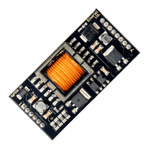
Ag210 PoE LED Driver Module
4 Introduction
This manual is intended to be a guide to using the “EvalAg210 Evaluation Board” with a
Silvertel Ag210 constant-current LED driver module with integrated IEEE compliant PD
module. The board is designed to handle 10/100/1000/10GBASE-T Ethernet data rates.
The Ag210 is pre-configured as a Type 3 Class 6 PD, capable of drawing 60W when
connected via a IEEE802.3bt compliant PSE. The AG210 is implemented with buck
converter topology and as such the input voltage supplied via PoE must be higher than
the string (output) voltage.
Figure 1: Board Layout
4.1 Link Settings
LK1 –Option Control
J7 –Auxiliary Voltage Adjust

Ag210 Evaluation Board User Manual
3
5 Board Description
5.1 Input
The EvalAg210 evaluation board is fitted with SilverTel’s Ag210 and can extract power
from an IEEE compliant PSE through its RJ45 connector J101.
5.2 Diode Bridge Selection
The EvalAg210 on-board diode bridge rectifiers will ensure that the correct input polarity
is applied to the Ag210 by extracting the power from the input center taps of T100 and
passing the voltage to the input of the Ag210.
Due to the amount of power and high currents involved in the IEEE802.3bt standard we
would recommend using SMC package Schottky diodes with low reverse leakage
current to be used as diode bridges. The EvalAg210 is fitted with SS36 Schottky diodes
configured as a diode bridge.
5.3 Input Signature
The EvalAg210 board will automatically direct the power from J101 to the Ag210’s input.
The Ag210 provides a 25K signature required to be powered from an IEEE compliant
PSE. The EvalAg210 has been designed to be powered from an IEEE802.3bt PSE such
as SilverTel’s Ag6800 PSE module. The Ag210 can also be powered by either a
IEEE802.3af or IEEE802.3at PSE, however the maximum possible output power may
be reduced.
5.4 PSE Detect
When the Ag210 has detected it is being powered via either a IEEE802.3bt type 3 or
IEEE802.3bt type 4 PSE the ‘bt Flag’ pin will be pulled low, this will cause LED3 to be
illuminated on the EvalAg210 board.
5.5 Output
An LED with a string voltage ranging from 2V up to 40V can be connected to either the
screw terminal labelled J6 or the Banana connectors, JP3 and JP4, with the Ag210 able
to provide a maximum power of 40W to the LEDs.

Ag210 Evaluation Board User Manual
4
5.6 Output Current Selection
The EvalAg210 is set to a constant current output of 300mA by default. To adjust the
power up to the maximum constant current output of 1000mA a resistance can be
installed between Vin- and LED- pins. Pads for R15 & R16 are provided to install the
appropriate resistors as per the table below. Installing resistors with an effective series
resistance of less than 0.713 may cause damage to the Ag210.
Iout CSxa Value (Ohms)* CSxb Value (Ohms)*
300mA Not Fitted Not Fitted
400mA 5R1 Not Fitted
500mA 2R49 Not Fitted
600mA 3R9 3R
700mA 2R49 2R49
750mA 3R 1R8
800mA 2R 2R
900mA 1R8 1R6
1000mA 1R0 2R49
Increase the constant output current, connect CSx between LED- and VIN-
* We would recommend a low temerature coeffient resistor with a package size of 1206, for the appropriate power
dissipation.
5.7 Auxiliary Voltage adjust
The Ag210 has an auxiliary DC voltage out for providing power to a control system. The
voltage level can be adjusted by placing a resistor between the VA and +Vout pins. The
header J7 on EvalAg210 allows the Ag210 to output either 12V, or 5V across JP5 &
JP6. However R13 can by populated to allow for a specified voltage, please contact
Silvertel for details.
With no jumper installed the output across the auxiliary supply will be 12V. Bridging pins
1&2 (C20 side) will result in an output of 5V. Bridging pins 2&3 (LED3 side) will result in
the custom set voltage across the output.
5.8 Dimming Control
The brightness control of the Ag210 LED driver can be controlled in several different
ways, using either the 0-10V DC voltage source, a Potentiometer or via an I2C
interface*. The EvalAg210 is setup to provide the latter two options.
With a jumper across LK1, the output power of the Ag210 will be controlled by the
potentiometer POT1.
With the jumper removed from LK1, the output power of the Ag210 will be controlled by
the I2C interface using the provided three pin header, J5. The pinouts on J5 are as
below. Pin 1: SCK Pin 2: SDA Pin 3: GND
*Please see section 6 of the datasheet for full explanation of the Ag210 dimming control.

Ag210 Evaluation Board User Manual
5
6 Typical Setup
6.1 Basic setup
Figure 3&4 shows example setups using the EvalAG210 evaluation board powered by
Silvertel’s EvalAG6800 PSE.
The equipment required: -
Power supply Input +57V IN e.g. Meanwell SP-240-48 available from mouser
which will give 57V
LED e.g. CREE 9-V CXA1304
Brightness controller e.g. on-board POT, external 0-10V DC controller or I2C
interface
Power Supply
J101
JP3&4
EvalAg210 Board
EVALAG6800 Board
CAT5e
Crossover
Cable
Power Ag210
57V - 3A Power Ag6800
J100
J101
J1&3
Power
Fuse
Dimming Control
POT1
Figure 2: Basic Setup
Figure 3: Typical Setup

Ag210 Evaluation Board User Manual
6
6.2 Data Input
To pass data via the Evaluation boards, the data input (e.g. Internet) can be connected
to J100 on the EvalAg6800 Board using a cat5e cable. The data is then passed
through the data transformer, where power is added and sent out via connector J101 of
the EvalAg6800 Board. The Data and power is extracted through J100 of the
EvalAg210 board and then divided into its separate power and data through the data
transformer. The data output is then available from J100 of the EvalAg210 Board, which
can then be connected to your device.
6.3 LED Array Protection
While not required for operation, it is always recommended to add a fusible element
between an LED Driver and the LED array, in order to reduce the risk of damage to
either element caused by an unexpected failure.
6.4 Ag210 Information
Full operating conditions and feature set can be found in the Ag210 product datasheet,
available from www.silvertel.com.

5V
SDASCL
LED_PWER -
LED_PWER +
SCL SDA
Vadj
Vadj
SMC SMC SMC SMC
SMCSMCSMCSMC
D9
SMAJ58
D9
SMAJ58
R103
75R
R103
75R
R12
NF
R12
NF
1
2
J6
ScrewTerminal
J6
ScrewTerminal
L6
FBMH3225HM102NT
L6
FBMH3225HM102NT
1
2
3
4
5
6
7
8
9
10
J100
3004S-8812-SMT
J100
3004S-8812-SMT
R102
75R
R102
75R
C106
10nF 250V
C106
10nF 250V
+
C20
470uF
+
C20
470uF
R101
75R
R101
75R
1
2
3
J7
Vadj Header
J7
Vadj Header
L7
FBMH3225HM102NT
L7
FBMH3225HM102NT
R100
75R
R100
75R
D5
SS36
D5
SS36
R106
75R
R106
75R
1
2
3
4
5
6
7
8
9
10
J101
3004S-8812-SMT
J101
3004S-8812-SMT
TDA
1DA+
2
DA-
3
TDB
4DB+
5
DB-
6
TDC
7DC+
8
DC-
9
TDD
10 DD+
11
DD-
12 XD- 13
XD+ 14
TXD 15
XC- 16
XC+ 17
TXC 18
XB- 19
XB+ 20
TXB 21
XA- 22
XA+ 23
TXA 24
T100
749052050
T100
749052050
R14
NF
R14
NF
R15
NF
R15
NF
POT1
24K
POT1
24K
1
2
3
J5
I2C Header
J5
I2C Header
1
2
JP3
RED
JP3
RED
C107
10nF 250V
C107
10nF 250V
LED3
LED
LED3
LED
R107
75R
R107
75R
D12
SS36
D12
SS36
LK1
LK
LK1
LK
L5
FBMH3225HM102NT
L5
FBMH3225HM102NT
1
2
JP6
BLACK
JP6
BLACK
D13
SS36
D13
SS36
C105
10nF 250V
C105
10nF 250V
D7
SS36
D7
SS36
1
2
JP4
BLACK
JP4
BLACK
Vin+
1
FLAG
2
IC
3
SDA 4
SDC 5
IC
6
IC
7
Vin-
8LED+ 9
LED- 10
Vin- 11
1-10 dim
12
opt 13
Vout+ 14
V adj 15
Vout-_2 16
Vout- 17
U7
Ag210
U7
Ag210
D6
SS36
D6
SS36
D10
SS36
D10
SS36
C108
1000pF 2KV
C108
1000pF 2KV
C104
10nF 250V
C104
10nF 250V
R16
NF
R16
NF
D11
SS36
D11
SS36
C103
10nF 250V
C103
10nF 250V
R13
1K62
R13
1K62
R105
75R
R105
75R
L4
FBMH3225HM102NT
L4
FBMH3225HM102NT
C102
10nF 250V
C102
10nF 250V
C101
10nF 250V
C101
10nF 250V
D8
SS36
D8
SS36
C109
1000pF 2KV
C109
1000pF 2KV
L3
FBMH3225HM102NT
L3
FBMH3225HM102NT
L2
FBMH3225HM102NT
L2
FBMH3225HM102NT
C100
10nF 250V
C100
10nF 250V
R104
75R
R104
75R
R17
6K34
R17
6K34
1
2
JP5
RED
JP5
RED

Date
Silver
Part No.
Description Value
Location: Qty: Package: Rating: Tol: Supplier Pt NO: Comments:
PD Module Ag210 U7 1 Custom - - Silver Telecom Part
Protection Diode SMAJ58A D9 1 SMA - - Vishay, Diodes Inc, Wurth- 824 500 581,
Diode Bridges SS36 D5-D8, D10-D13, 8 SMC - - Vishay, Fairchild
Transformer - Data 10G BaseT PoE+ T100 1 SMT - - Wurth 749052050
Ferrite Chip
≥1000Ω@100MHz L2-L4, L5-7 6 0805 ≥ 1A 25% TDK MPZ2012S102A, Wurth 742792096
SM LED RED LED LED3 1 SMT - - Wurth - 150 141 RS7 310 0
Capacitor Electolytic 470µF C20 1 Through Hole 16V 20% Multicomp MCGPR25V477M10X16, Wurth 860040475008
Ceramic multi-layer 1000pF 2KV C108, C109 21206 2KV 20% Samsung, NIC, TDK, Murata, Kemet & AVX, Wurth-885342208024
Ceramic multi-layer 10nF C100 - C107 8 0805 250V 20% Samsung, NIC, TDK, Murata, Kemet & AVX WE_885342207010
Resistor - 0603 0R R12, R14 NF 1206 63mW 1% Royal Ohm, Eurohm & Yageo
Resistor - 0603 1k62 R13 NF 0603 63mW 1% Royal Ohm, Eurohm & Yageo
Resistor - 0603 1R0 ±100ppm/K R15 NF 1206 250mW 1% Royal Ohm, Eurohm & Yageo
Resistor - 0603 2R49 ±100ppm/K R16 NF 1206 250mW 1% Royal Ohm, Eurohm & Yageo
Resistor - 0603 6K34 R17 1 0603 63mW 1% Royal Ohm, Eurohm & Yageo
Resistor - 0805 75R
R100 - R107 80805 125mW 1% Royal Ohm, Eurohm & Yageo
Potentiometer 24K - linear
POT1 1Through Hole 1W 91A1A-B28-B17L (Farnell-9357777)
Red Connecor 4mm PCB Socket JP3, JP5 2 Through Hole - - Hirschmann 973582100
Black Connector 4mm PCB Socket JP4, JP6 2
Through Hole - - Hirschmann 973582101
DC Power Connector 2 WAY SCREW TERMINAL J6 1 Through Hole - - Farnell - 2008004
Ethernet Connector RJ45 J100, J101 2 SMT - - Toby 3004S-8821-SMT
Link 2 Way LK1 1 Through Hole - - Toby LHCS-02S-R-060-034, Wurth 61300211121
Link 3 Way J5, J7 2 Through Hole - - Toby LHCS-03S-R-060-034, Wurth 61300311121
8 Way U1a 1 Through Hole - - Toby SLW-108-01-G-S WE_61300811821
9 Way U1b 1 Through Hole - - Toby SLW-109-01-G-S WE_61300911821
PCB Rev.1R - mm xmm -
Jumper Links Links LK1, J7 2 - -
51 Total
EvalAg210 - Rev-1R 9th January 2020
***'Strictly Private and Company Confidential***
Module Socket
Table of contents
Other Silvertel Motherboard manuals
Silvertel
Silvertel Ag9330 User manual
Silvertel
Silvertel EVALAG5300 User manual

Silvertel
Silvertel EvalAg5800 User manual
Silvertel
Silvertel EvalAg7300 User manual

Silvertel
Silvertel POE Ag5810 User manual

Silvertel
Silvertel EVALAG6100 User manual

Silvertel
Silvertel Ag9800M User manual
Silvertel
Silvertel Ag103 User manual

Silvertel
Silvertel EVALAg7100 User manual
