Silvertel Ag103 User manual

Ag103 Evaluation Board
User Manual
Rev 1.0 – October 2015
Silvertel

Ag103 Evaluation Board User Manual 1
1 Table of Contents
1Table of Contents 1
2Table of Figures 1
3Introduction 2
4Board Description 2
4.1 Input.................................................................................................................2
4.2 Output .............................................................................................................. 3
4.3 Capacity Selection............................................................................................3
4.4 Simulated Thermal Offset................................................................................. 4
4.5 Status Output ...................................................................................................4
4.5.1 Mode 0 – Bulk Charge Operation 5
4.5.2 Mode 1– Float Charge 5
4.5.3 Mode 2 – Over Current 5
4.5.4 Mode 3 – Over Temperature 5
4.5.5 Mode 4 – Disconnected battery 5
4.5.6 Mode 5 - Input Voltage Removed/ No Solar Power 6
5Using the Board 6
6EVALAg103 Evaluation Board Schematic 7
2 Table of Figures
Figure 1: Board Layout....................................................................................................2
Figure 2: Capacity selection link......................................................................................3
Figure 3: Example set-up................................................................................................6
Figure 4: EVALAg103 R1 Schematic ..............................................................................7

Ag103 Evaluation Board User Manual 2
3 Introduction
This manual is a guide to using the “EVALAg103” (Rev R1) evaluation board with our
Ag103 Sealed Lead Acid (SLA) solar battery charger module. The EVALAg103
evaluation board can be powered by either a 21V open circuit solar panel, or a bench
power supply with a range of 9V to 36V. This will charge SLA batteries with a capacity
between 1.2Ah and 12Ah.
4 Board Description
4.1 Input
The input power is supplied to the board through connector J1 or J2 (see Figure 1). J1
is a standard 2.5mm DC10 connector with the centre pin of the connector being positive
and the outer is negative. J2 is a screw terminal with pin 1 as the positive input. The
input current can be measured by removing LK1 and connecting an ammeter across
these pins.
LED1 will be illuminated when the input supply is ON.
Figure 1: Board Layout
Ag103 Evaluation Board User Manual 3
4.2 Output
The output connections to the SLA battery are made through JP2 (positive) and JP3
(negative) with added protection of F1 as a 8A fuse and D1 as a 10A diode, to protect
an over current or short for either the load or battery. The Load Output connections are
available through JP1 (positive) and JP4 (negative).
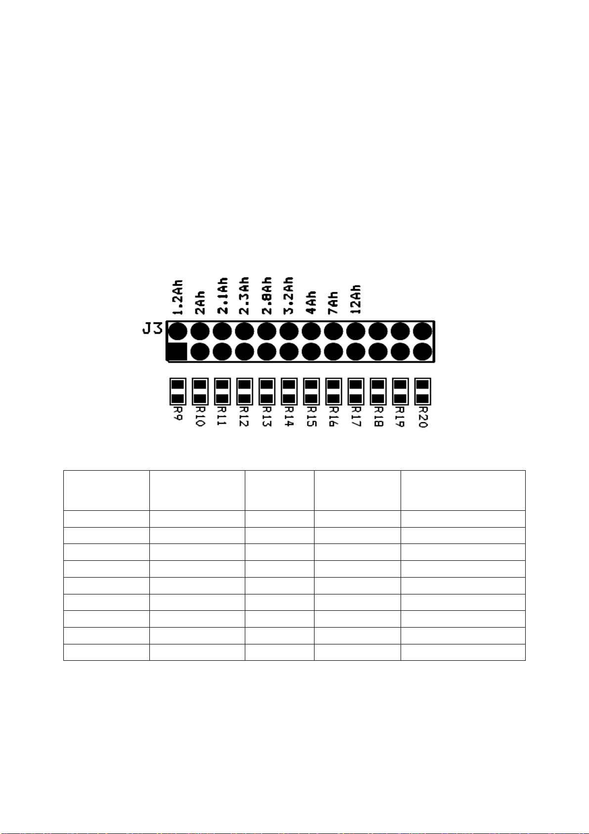
4.3 Capacity Selection
The EVALAg103 evaluation board can set the Ag103 capacity from 1.2Ah to 12Ah by
setting the corresponding jumper link on J3 (see Figure 2 and Table 1).
Figure 2: Capacity selection link
J6 Resistor
Selection Battery Capacity
(Ah)
R
CS
Resistance
(Ohms)*
Min Input
Voltage (V) Bulk Charge Current
Limit (A) ±10%
R9 1.2 1K ±1% 9 0.3
R10 2 2K ±1% 9 0.5
R11 2.1 3K ±1% 9 0.525
R12 2.3 3K9 ±1% 9 0.575
R13 2.8 4K7 ±1% 9 0.7
R14 3.2 6K2 ±1% 12 0.8
R15 4 6K8 ±1% 12 1
R16 7 7K5 ±1% 12 1.2
R17 12 9K1 ±1% 12 1.2
Table 1: Output Connections
Note: to prevent damaging the battery it is important that the correct value of RCS is set. If the selector link is not fitted, then the
Ag103 will default to 1.2Ah capacity.

Ag103 Evaluation Board User Manual 4
4.4 Simulated Thermal Offset
During Float charge SW1 can be used to demonstrate how the voltage changes to
compensate for the change in battery temperature if an appropriate thermistor is fitted.
With both switch positions open, the Ag103 will default to a 25ºC ambient charge
voltage.
When switch No. 1 is closed, placing R7 (20K) to ground, this will simulate a battery
temperature higher than 25ºC and the output voltage will decrease (this response will be
slow when the Ag103 is float charging).
When switch No. 2 is closed, placing R8 (220K) to ground, this will simulate a battery
temperature lower than 25ºC and the output voltage will increase.
When both switches are closed this will simulate a battery temperature higher than
50ºC, the output will switch OFF and the Status LED (2) will flash in mode 3. Opening
one or both switches will return the Ag103 to its normal charge mode.
4.5 Status Output
The Ag103 has a status indication output pin ‘STAT’; that can be either connected to a
µ-controller input for full status monitoring, via connector J4, or can be used with an
LED as an indicator by fitting a link on LK2.
If LK2 is fitted then LED 2 will be illuminated with the sequences detailed below and
shown in Table 2: -
Mode
Status Mode STAT Output
0 Bulk Charge Operation Steady State ‘Logic 1’
1 Float Charge 50% ‘Logic 1’ 50% ‘Logic 0’
2 Over Current Error 1 Pulse
3 Over Temperature Error 2 Pulses
4 Disconnected Battery Error 3 Pulses
5 Input Voltage Removed / No Solar Power Steady State ‘Logic 0’
Table 2: STAT Output Conditions
*For further information on the timing of the STAT output please see Figure 8 of the
Ag103 datasheet.

Ag103 Evaluation Board User Manual
5
4.5.1 Mode 0 – Bulk Charge Operation
Once the Ag103 has checked the battery capacity and sees a 12V battery connected it
will power up and the ‘STAT’ pin will output a steady state 'logic 1'.
The Ag103 will continue to output this state until the battery has reached it's 80%
charge before switching to float charge and enters Mode 1.
4.5.2 Mode 1– Float Charge
After the battery has reached it's 80% charge the Ag103 will change it's charging status
to float charge by dropping it's terminal voltage down to ~13.65V. The 'STAT' pin will
drop to a logic 0 for 1s and then back to a logic 1 for 1s. This cycle will repeat itself over
the period of its float charge.
4.5.3 Mode 2 – Over Current
If an output over current condition is detected, the Ag103 will shutdown its DC-DC
converter and will go into Mode 2. The STAT pin will drop to a logic 0 for 100ms,
followed by a logic 1 for 100ms before returning to a logic 0. The Ag103 will then reset
and wait 2 seconds before re-attempting to power up. If the over current is still there
when trying to power up, the Ag103 will immediately shut back down and repeat the
process. Once the over current has been removed the Ag103 will return to Mode 0 (bulk
charge operation).
4.5.4 Mode 3 – Over Temperature
If a battery over temperature condition occurs, the Ag103 will shutdown its DC-DC
converter to protect the battery and enter Mode 3. The STAT pin will drop to a logic 0 for
100ms before generating two logic 1 pulses, with a 100ms mark and 100ms space. This
will repeat over a 2s period until the battery temperature has dropped below 50˚C (the
maximum operating temperature). Once the battery temperature has dropped below
50˚C the Ag103 will return to Mode 0 (bulk charge operation).
4.5.5 Mode 4 – Disconnected battery
If the battery is disconnected or there is no battery present at power up, the Ag103 will
shutdown its DC-DC converter, go into Mode 4 and output three 100ms logic 1 pulses,
with a 100ms mark and 100ms space. This will repeat over a 2s period until a 12V
battery is connected. When a 12V battery is connected the Ag103 will go into Mode 0
(bulk charge operation).

Ag103 Evaluation Board User Manual 6
4.5.6
Mode 5 - Input Voltage Removed/ No Solar Power
When the input voltage is removed or the solar panel can no longer provide any power
to the Ag103, the STAT pin will output a logic 0 until power has been reconnected or the
panel can provide enough power to charge the connected battery.
5 Using the Board
Figure 3 shows an example set-up using the Ag103 to charge a 12Ah SLA battery from
a solar panel. For a 12Ah battery the J3 link is set to the R17 position.
Ag103
EVALAg103
Board JP3
JP2
J1
12V 12Ah
Battery
Load
JP1
JP4
21Voc
Figure 3: Example set-up

Ag103 Evaluation Board User Manual
7
6 EVALAg103 Evaluation Board Schematic
Figure 4: EVALAg103 R1 Schematic

Table of contents
Other Silvertel Motherboard manuals

Silvertel
Silvertel EvalAg5800 User manual

Silvertel
Silvertel EVALAG6100 User manual

Silvertel
Silvertel EvalAg7300 User manual

Silvertel
Silvertel Ag210 User manual

Silvertel
Silvertel Ag9330 User manual

Silvertel
Silvertel EVALAG5300 User manual

Silvertel
Silvertel Ag9800M User manual

Silvertel
Silvertel POE Ag5810 User manual

Silvertel
Silvertel EVALAg7100 User manual
Popular Motherboard manuals by other brands


Texas Instruments
Texas Instruments INA296EVM user guide

IEI Technology
IEI Technology PICOe-HM650 user manual

ASROCK
ASROCK Z390 Phantom Gaming 9 user manual

Altera
Altera EN5319QI user guide

JETWAY
JETWAY JNP891P Series quick start guide

SpinCore Technologies
SpinCore Technologies PulseBlaster128 owner's manual


