Silvertel EvalAg7300 User manual

V1.0 May 2023
Evaluation Board User Manual
Evaluation Board
User Manual
© Silver Telecom 2023
Silvertel
EvalAg7300
Evaluation Board
User Manual
Version 1.0 –May 2023

User Manual
V1.0 May 2023
© Silver Telecom 2023
2
EvalAg7300
High Power Isolated Boost Converter
Evaluation Board
Table of Contents
1Kit Contents............................................................................................................................................. 3
2Board Layout........................................................................................................................................... 3
Link Settings..................................................................................................................................... 3
Input Output Connections................................................................................................................. 3
3Introduction ............................................................................................................................................. 3
4Input ......................................................................................................................................................... 4
Supply............................................................................................................................................... 4
Output Voltage Adjust ...................................................................................................................... 4
5Output ...................................................................................................................................................... 4
Output Power LED ........................................................................................................................... 4
6Test Setup................................................................................................................................................ 5
7Additional information............................................................................................................................ 5
8Schematic ................................................................................................................................................ 6
9Bill of Materials........................................................................................................................................ 7
10 Layer Routing.......................................................................................................................................... 8
Table of Figures
Figure 1: EvalAg7010 Board Layout.................................................................................................................. 3
Figure 2: Basic Test Setup ................................................................................................................................ 5
Figure 3: IEEE802.3bt PSE Test Setup............................................................................................................. 5
Figure 4: Schematic........................................................................................................................................... 6
Figure 5: Bill of Materials................................................................................................................................... 7
Figure 6: Top Layer Routing.............................................................................................................................. 8
Figure 7: Bottom Layer Routing......................................................................................................................... 8
User Manual
V1.0 May 2023
© Silver Telecom 2023
3
EvalAg7300
High Power Isolated Boost Converter
Evaluation Board
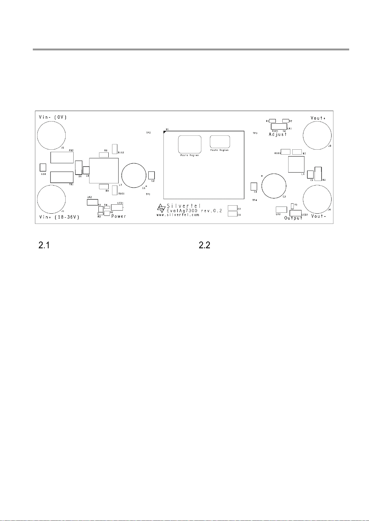
1 Kit Contents
➢EvalAg7300 Evaluation Board
➢Ag7300 Soldered to Evaluation Board
2 Board Layout
Figure 1: EvalAg7010 Board Layout
Link Settings
LK1 –Output voltage Adjust
LK2 –Input Power LED Enable
LK3 –Output Power LED Enable
Input Output Connections
J2 & J3 –Supply Binding Posts
J3 & J4 –Load Output Binding Posts
3 Introduction
This Manual is a guide to using the EvalAg7300 evaluation board fitted with a Silvertel
Ag7300 High Power Isolated Boost Converter module for use in a wide variety of point of
load (PoL) and DC-DC converter applications, including IEEE802.3bt Power over Ethernet
(PoE) Power Sourcing Equipment (PSE) applications.
While this evaluation board has been designed following Silvertel's recommendations, it
should not be considered as a reference design as it features circuity included solely for
the purposes of evaluation that are not be required for proper operation.

User Manual
V1.0 May 2023
© Silver Telecom 2023
4
EvalAg7300
High Power Isolated Boost Converter
Evaluation Board
4 Input
Supply
The EvalAg7300 evaluation board should be powered by a DC Power supply connected to
J1 and J2 binding posts using 4mm Banana connectors, bare wire, or fork connectors.
This supply should deliver between 18-36V. The Ag7300 can output up to 120W of
continuous output power, at this output power the Ag7300 will dissipate up to 16W. Any
power source should be suitably rated for the desired output power, the power dissipation
of the Ag7300 and any transmission power losses. For example, a 24V supply should be
capable of supplying up to 7A if the full output power is to be drawn.
Output Voltage Adjust
The output voltage of the Ag7300 module can be adjusted up or down by changing the
location of the jumper LK1. The EvalAg7300 is fitted with two adjust resistors. The down
adjust resistor R1, is fitted with a 510kΩ resistor. And the up adjust resistor R6, which is
fitted with a 0Ω resistor to allow for the maximum adjust change of the Ag7300LPB
module.
With no jumper present on LK1, the module will default to its nominal 55.5V output.
To increase the output voltage, insert the jumper to LK1 in the left position, so that the link
is between the middle and rightmost pin.
To reduce the output voltage, insert a jumper to LK1 in the right position, so that the link is
between the middle and leftmost pin.
If the output voltage needs to be set to a different value (within the adjustment range) then
connect different value resistors in place of R1 (510kΩ) or R2 (0Ω) and connect the jumper
into the corresponding link setting.
Note: ensure that the down adjust resistor is not shorted when connecting a module that has a higher stated resistance in the
datasheet, as this could cause damage to the module.
5 Output
The Ag7300 will output 48V-58V and can deliver a continuous output current of 2.2A, for
up to 120W of continuous power, the peak output power may be reduced as a result of the
power source or operating conditions the module is operating in.
Output Power LED
LED2 illuminates when the module is outputting. This can be disabled by removing the
jumper link LK3, removing this link does not affect the power being supplied by the
Ag7300LPB.
User Manual
V1.0 May 2023
© Silver Telecom 2023
5
EvalAg7300
High Power Isolated Boost Converter
Evaluation Board
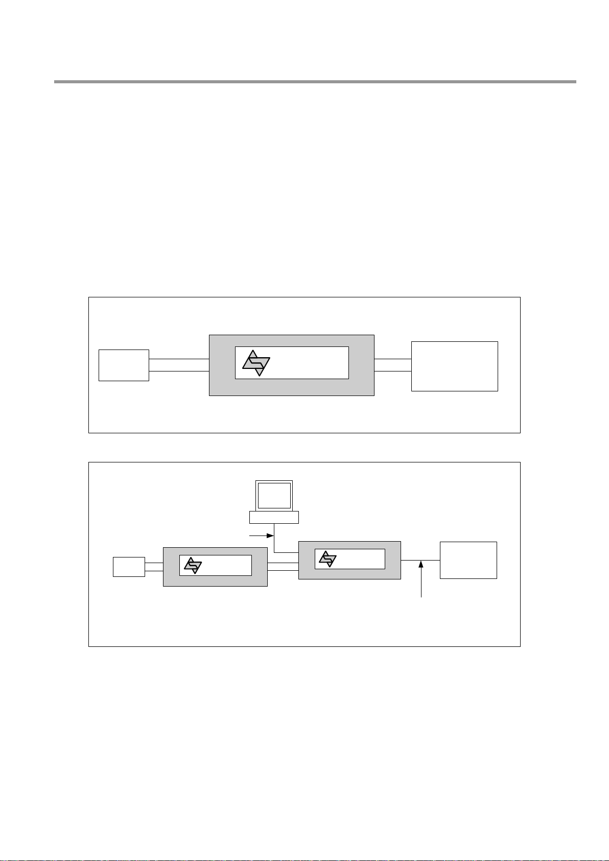
6 Test Setup
Figures 2 and 3 show typical test setups using the EvalAg7300 evaluation board.
The equipment required: -
➢EvalAg7300 fitted with Silvertel’s Ag7300LPB Module
➢18-36V bench power supply Optional Equipment capable of greater than 140W
Optional Equipment
➢EvalAg6800 or other IEEE802.3 compliant PSE
➢EvalAg5800 or other IEEE802.3 compliant PD
➢Data source e.g. PC
➢CAT5e or greater cables
Figure 2: Basic Test Setup
Figure 3: IEEE802.3bt PSE Test Setup
7 Additional information
Full operating conditions and feature set can be found in the Ag7300 product datasheet,
available from www.silvertel.com.
EvalAg7300
J1 application Device
18-36V DC
Power Supply J2
J3
J4
CAT5e
Patch
Cable Data Data&
Power
PC
Power
Application
e.g. IEEE802.3bt
compliant PD
EvalAg6800
J100 J101
J3
CAT5e
Cable
EvalAg7300
J1
18-36V
DC
Power
Supply J2 J3
J4

User Manual
V1.0 May 2023
© Silver Telecom 2023
6
EvalAg7300
High Power Isolated Boost Converter
Evaluation Board
8 Schematic
Figure 4: Schematic
User Manual
V1.0 May 2023
© Silver Telecom 2023
7
EvalAg7300
High Power Isolated Boost Converter
Evaluation Board
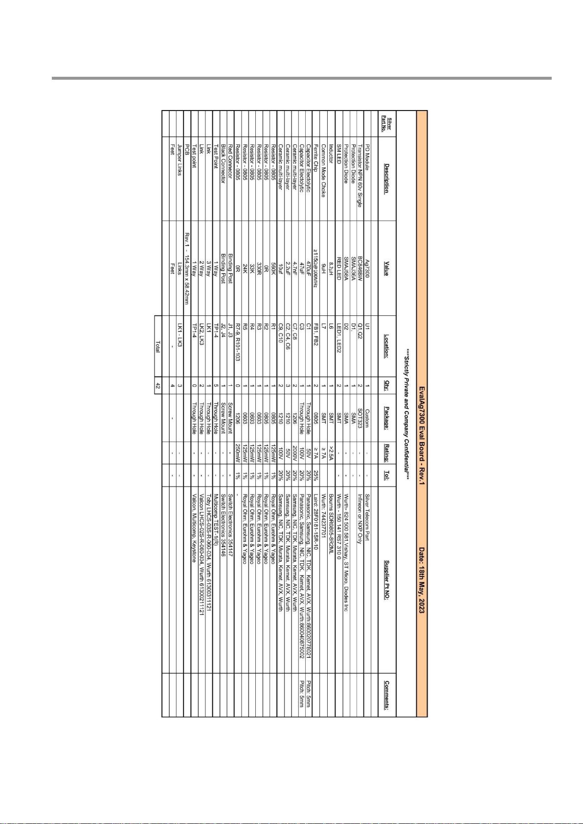
9 Bill of Materials
Figure 5: Bill of Materials

User Manual
V1.0 May 2023
© Silver Telecom 2023
8
EvalAg7300
High Power Isolated Boost Converter
Evaluation Board
10 Layer Routing
Figure 6: Top Layer Routing
Figure 7: Bottom Layer Routing
Table of contents
Other Silvertel Motherboard manuals

Silvertel
Silvertel Ag9800M User manual

Silvertel
Silvertel POE Ag5810 User manual

Silvertel
Silvertel EVALAG5300 User manual

Silvertel
Silvertel EVALAg7100 User manual

Silvertel
Silvertel Ag9330 User manual

Silvertel
Silvertel Ag210 User manual

Silvertel
Silvertel EVALAG6100 User manual

Silvertel
Silvertel EvalAg5800 User manual

Silvertel
Silvertel Ag103 User manual


