Ag9330 Evaluation Board User Manual 4
4.3 Input Termination
EVALAG9800M evaluation board has the build option to add input data termination, see
the apps note “ANX-POE-Data-Termination” on our website for more information.
4.4 Class Programming
The Ag9800M is internally set to Class 0, so the EVALAG9800M evaluation board does
not have any class programming.
4.5 Data Output
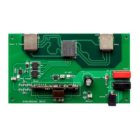
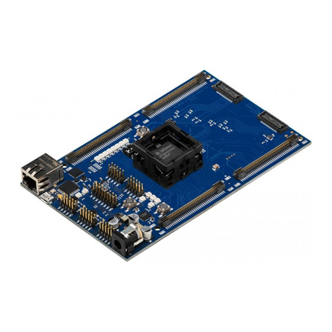
The output data is transmitted from the evaluation board via J2.
4.6 Power Output
The Ag9800M output is delivered from connectors J3 (positive) and J4 (negative). In
addition to these the output voltage is also available from J5 (the centre pin is positive).
LED1 is illuminated when the Ag9800M output is ON.
The link LK3 needs to be set to the either “3V&5V” or “12V”.
4.7 Output Adjustment
The output voltage of the Ag9800M can be adjusted by connecting the ADJ pin to either
the -VDC or the +VDC pins. LK2 can be used to adjust the output voltage (see Figure
1).
On the EVALAG9800M evaluation board R1 and R2 are fitted with a 0 Ohm link to give
its full adjustment, see the output adjustment section in the datasheet for more
information.
With LK2 fitted in position “a” (centre to right) the output voltage will be decreased.
With LK2 fitted in position “b” (centre to left) the output voltage will be increased.

