Ag9330 Evaluation Board User Manual 4
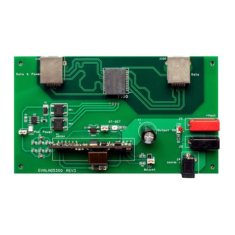
If PoE in not available, the Ag9330 can be powered from one of the two auxiliary inputs.
The first auxiliary input can be connected to an ac power supply (20Vac to 40Vac) via
the AUX AC connector J8 .If LED4 is illuminated then there is power on the AUX AC
input.
Note: LED2 also illuminates if a valid AUX AC Input is present.
The second auxiliary input can be connected to a dc power supply (7Vdc to 15Vdc) via
J6 (positive) & J7 (negative). If LED5 is illuminated then there is power on the AUX DC
input.
4.2 Class Programming
The Ag9330 is internally set to Class 4, when the module is connected to an
IEEE802.3at compliant PSE, LED 3 “AT Detect” will be illuminated.
4.3 Data Output
The output data is transmitted from the evaluation board via J2.
4.4 Output Adjustment
The output voltage of the Ag9330 can be adjusted by connecting the ADJ pin to either
the -VDC or the +VDC pins. LK4 can be used to adjust the output voltage (see Figure
1).
On the EVALAG9330 evaluation board R2 and R4 are fitted with a 0 Ohm link to give
maximum adjustment, see the output adjustment section in the datasheet for more
information.
With LK4 fitted in position “a” (centre to top) the output voltage will increase.
With LK4 fitted in position “b” (centre to bottom) the output voltage will decrease.
