Simco-Ion Ioncell User manual

5201128 Rev. D
Ioncell
Ioncell
Standard and In-Line Ionizer
INSTALLATION AND OPERATING INSTRUCTIONS

i
Ioncell 5201128 Rev. D
TABLE OF CONTENTS
1. SAFETY WARNINGS.................................................................................................1
2. DESCRIPTION .........................................................................................................2
3. SPECIFICATIONS .....................................................................................................3
4. INSTALLATION ........................................................................................................4
5. MAINTENANCE........................................................................................................8
6. PARTS AND ACCESSORIES......................................................................................9
9. WARRANTY AND SERVICE ................................................................................... 10
1
Ioncell 5201128 Rev. D
1. SAFETY WARNINGS
PLEASE READ INSTRUCTIONS COMPLETELY BEFORE STARTING
INSTALLATION
ALL INSTALLATION AND TROUBLESHOOTING OPERATIONS MUST
BE PERFORMED BY QUALIFIED TECHNICAL PERSONNEL
This instruction manual uses symbols to identify dangerous situations as follows:
NOTE – Statements identified with NOTE indicate precautions necessary
to avoid potential equipment failure.
CAUTION – Statements identified with CAUTION indicate potential
safety hazards.
ATTENTION – Les déclarations identifiées avec ATTENTION indiquent
des dangers potentiels pour la sécurité.
WARNING – Statements identified with WARNING indicate potential
serious injury hazards.
AVERTISSEMENT – Les déclarations identifiées avec AVERTISSEMENT
indiquent un risque de blessures graves.
NOTE – This equipment must be correctly installed and properly
maintained. Adhere to the following notes for safe installation and operation:
WARNING – Fire Hazard
Keep the unit dry. Do not operate the unit in flammable or explosive
environments.
AVERTISSEMENT – Risque d’incendie
Gardez l’appareil au sec. Ne pas utiliser l’appareil dans des environnements
inflammables ou explosifs.
2
Ioncell 5201128 Rev. D
CAUTION – Electrical Shock Hazard
Turn off power supply before cleaning bar or performing any maintenance
on the system. Electrical installation and repairs must be performed by a
skilled electrical engineer according to the applicable national and local
regulations. The equipment must be properly grounded. Grounding is
required to ensure safe and proper operation and to prevent electrical shocks
upon contact.
ATTENTION – Risque de choc électrique
Coupez l’alimentation électrique avant de nettoyer la barre ou d’effectuer
un entretien sur le système. L’installation électrique et les réparations
doivent être effectuées par un ingénieur électricien qualifié conformément
aux réglementations nationales et locales en vigueur. L’équipement doit être
correctement mis à la terre. La mise à la terre est nécessaire pour assurer un
fonctionnement sûr et approprié et pour éviter les chocs électriques lors du
contact.
CAUTION – Sharp Points
Risk of injury. Keep hands/fingers away.
ATTENTION – Points pointus
Risqué de blessure. Gardez les mains / doigts éloignés.
1. Read Instruction Manual completely before proceeding with installation or
operation. Failure to follow instructions may result in damage to Ioncell ionizer
or power supply.
2. The Ioncell ionizer, when operated with optional power supply, is to be
connected to main electric source with included 3-wire line cord and grounded
plug set. Do not remove electrical ground pin of the plug set.
3. A factory-qualified service technician must perform any required ionizer service
or warranty repairs. Please contact Simco-Ion Customer Service at 215-822-
6401 for information.
2. DESCRIPTION
The Simco-Ion Ioncell is a compact, steady state, bi-polar DC air ionizer designed
for easy installation, and minimal maintenance. It provides powerful ionization
through output tubes up to four feet in length. The single output tube also has the
ability to be split, allowing the Ioncell to service multiple locations from a single
ionization source. Options for Ioncell include:
• Standard: A fan for increased operating range
• In-Line:
– A ring or air knife output applicator for custom applications
– An airflow switch that automatically cuts off power when no airflow is
present, so potential excess ozone production is eliminated
3
Ioncell 5201128 Rev. D
The ionizer can be powered by a universal input, low voltage power supply, or
through a 24 VDC power bus in the host main circuit. Multiple Ioncells can be
linked together from a single power supply, allowing up to 6 units to be daisy-
chained.
Operation of the Ioncell is automatically regulated by built-in proprietary circuitry.
A green light on the face of the ionizer indicates active condition. A red light
will indicate if a fault condition has occurred. Mounting holes for the ionizer are
provided within the integral base of the unit.
The in-line Ioncell is equipped for use with pressurized CDA only (clean dry air).
Ioncell emitter points are general purpose Tungsten.
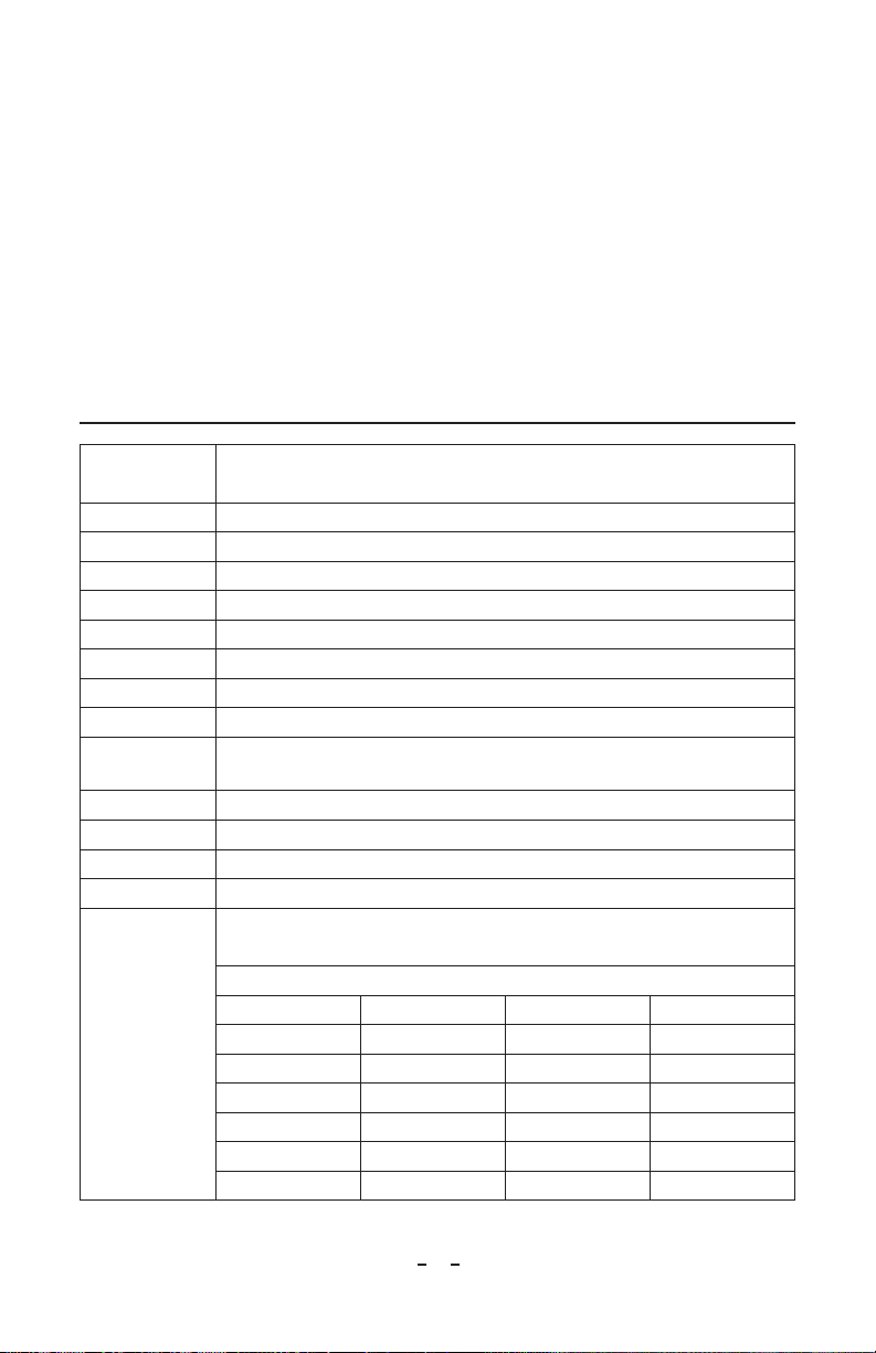
3. SPECIFICATIONS
Input Voltage Power Supply: Universal, 100-240VAC, 50/60 Hz (24VDC, 1.6A output)
Ioncell: 24VDC, 0.1A (0.17A with optional fan)
Output Voltage ±4500 VDC, 5µA, Steady State
Offset Voltage ±50V
Enclosure White Polycarbonate (UL 94V-0 flammability rating)
Alarm Output TTL level alarm output
Indicators Green, POWER ON; Red, FAULT
Mounting Integral mounting flanges accept four (4) #4 or #6 [M3 or M4] screws (not supplied)
Emitter Pins Four (4), Tungsten
Operating Temp 32-122°F [0-50°C]; non-condensing
Dimensions Standard: 1.25”H x 1.3”W x 4.5”L [32 x 33 x 115 mm]
In-Line: 2.5”H x 1.3”W x 4.5”L [64 x 33 x 115 mm]
Weight 5.2 oz [145g]
Gas Input In-Line: 45 psi [3.1 bar] max; clean dry air only
Gas Flow In-Line: 0.8 scfm @ 5 psi to 3.2 scfm @ 45 psi [23 l/m @ 0.34 bar to 92 l/m @ 3.1 bar]
Airflow 5 cfm [0.14 m3/min] with optional fan
Discharge Time
Standard Ioncell: <15 seconds @ 6”[150 mm] to CPM plate 1000-100V
Ioncell with optional fan: <10 seconds @ 12”[300 mm] to CPM plate
In-Line Ioncell with output tube: 1”[25 mm] to CPM plate, 1000-100V
Tube Length 30 psi [2.0 bar] 15 psi [1.0 bar] 5 psi [0.34 bar]
6”[150 mm] 0.5 sec 0.8 sec 1.4 sec
12”[300 mm] 0.8 sec 1.4 sec 2.2 sec
18”[460 mm] 1.0 sec 2.1 sec 3.5 sec
24”[610 mm 1.8 sec 3.2 sec 5.2 sec
36”[910 mm] 6.0 sec 6.8 sec 10 sec
48”[1220 mm] 9.5 sec 13 sec 22 sec

4
Ioncell 5201128 Rev. D
4. INSTALLATION
CAUTION – Sharp Points
Risk of injury. Keep hands/fingers away.
ATTENTION – Points pointus
Risqué de blessure. Gardez les mains / doigts éloignés.
NOTE – Inspect shipping container and contents for visible damage.
Report any damage directly to the carrier before attempting installation of
unit.
The Ioncell ionizer is designed for fixed position mounting onto a secure equipment
frame or partition surface. The flanged base of the ionizer may be used as a template,
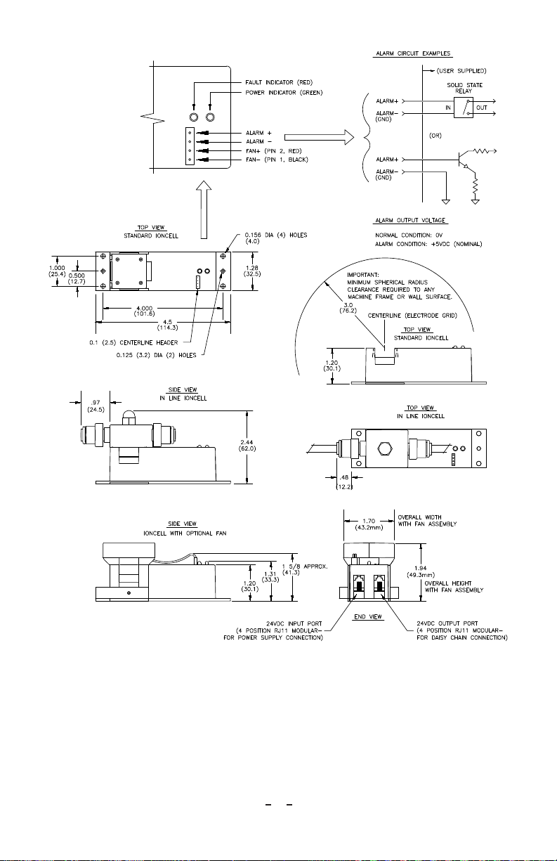
or see Figure 2 for complete dimensional information.
Prepare mounting surface with necessary mounting holes. Secure with #4 or #6 [M3
or M4] screw hardware as required. Mounting hardware is not supplied with unit.
Important mounting location requirement: The center of ionizer’s emitter pin grid
must have a minimum 3” spherical radius clearance to any adjacent equipment
frame or wall surface. A clear line of sight is recommended to the area requiring
static neutralization for best ionizer performance.
CAUTION – This product is intended to be supplied by a Listed AC
Adapter or Power Unit marked “Class 2” or “LPS” and rated output 24
VDC, 1.7A.
ATTENTION – Ce produit est destiné à être alimenté par un adaptateur
de courant alternatif ou transformateur listé “ classe 2 “ ou “ LPS “ et avec
une puissance nominale 24 VDC, 1.7A.
Optional fan assembly mounting and connections: Engage open end of fan assembly
directly around emitter pin grid area of the ionizer, until it snaps into place. Secure
fan assembly by placing fan locking bracket over base of fan assembly and tightening
set screws (do not over tighten). Insert power lead connector of fan assembly into
socket located in the top of ionizer enclosure. The black wire, pin 1 in the connector
must be positioned towards the outside of ionizer enclosure. See Figure 2 for
complete connection diagram.
After the ionizer mounting has been completed, connect power cable between
ionizer and power supply. Secure power supply as necessary. Connect line cord from
power supply to the main electric source. The green light on ionizer will indicate
normal operation.
5
Ioncell 5201128 Rev. D
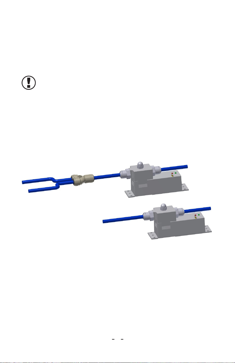
In-line Ioncell connections: An in-line manifold is mounted within the emitter pin
grid area of ionizer. The in-line manifold allows for multi-tube configurations for
locations which have been previously inaccessible for other ionizers. The input and
output connectors both take 1/4” OD tubing. Insert tubing into connector and run
tube to desired location, or, use a 2-way splitter to direct ionization to two different
locations. For optimal performance, use shortest tube lengths possible. Excessive
tube lengths will increase discharge times.
NOTE – Tubing must have the same inside diameter on both sides of the
in-line manifold.
A +5 VDC (TTL level) alarm output is provided for remote monitoring of the
ionizer operating condition. ALARM+ goes high (+5 VDC) on alarm. See Figure
2 for complete connection diagram.
Optional Airflow Switch for In-line Ioncells: The airflow switch replaces the power
cable between the ionizer and power supply. It includes two 1/4” tubing connectors,
labeled “AIR INPUT” for the compressed air supply and “AIR OUTPUT” to be
connected to the ionizer. The In-line Ioncell will switch power to the ionizer off
when compressed air is not being fed to the assembly.
Figure 1. Output Tube Congurations (single and split)

6
Ioncell 5201128 Rev. D
with Optional Fan
In Line Ioncell Module
Standard Ioncell Module
Universal Power Supply
with 6" [150 mm] long cable
and panel mountable RJ-11
modular connector
RJ-11 extension cable
72" [1830mm] long
(included with power supply)
RJ11 extension cable
36" [915 mm] long
(included with Ioncell ionizer)
Line Cord
72" [1830 mm] long
(included with power supply)
Red
Black
Direct Power Bus Cable
72" [1830 mm] long
(units with no power supply)
Customer supplied 24 VDC
Figure 2. Up to 6 (six) Ioncells can be attached to one power supply
7
Ioncell 5201128 Rev. D
Figure 3. Dimensional Drawing

8
Ioncell 5201128 Rev. D
5. MAINTENANCE
The Ioncell ionizer is designed for calibration free operation with a minimum of
maintenance and cleaning. There are no user serviceable parts within the ionizer. No
attempt should be made to disassemble or repair defective products. Please contact
Simco-Ion customer service for information concerning repair or replacement.
NOTE – All corona type ionizers form deposits on the emitter electrodes
during normal service. Typical deposits appear as a white coating upon the
pointed tip region of the electrode. Periodic cleaning of the pointed tips will
maintain the performance and extend the life of the ionizer. Maintenance
frequency will depend on the relative humidity and cleanliness of the
location where the ionizer is operated.
Occasional cleaning of the ionizer housing may be accomplished with a clean cloth
moistened with common glass cleaning solution.
The recommended emitter cleaning procedure is as follows:
1. Turn the ionizer off by disconnecting it from the electrical power source.
2. Simco-Ion recommends using the ITW-TEXWIPE model TX726, Crush Tube
product for cleaning the emitter electrodes. (Follow ITW-TEXWIPE product
instructions) A substitute method consists of a cleanroom swab saturated in a
cleaning solution of isopropyl alcohol and de-ionized water.
3. Prepare the Crush Tube or swab for use. Insert it directly onto the point of the
electrode (CAUTION: SHARP PINS, AVOID CONTACT), rotate slowly,
and withdraw. Repeat this process until all visible deposited material has been
removed.
4. Allow cleaning solution to dry completely before returning the ionizer to
service.

9
Ioncell 5201128 Rev. D
6. PARTS AND ACCESSORIES
Parts Part Number
Standard Ioncell Ionizer Kit with Power Supply, includes items 1, 3 below 4017139
Standard Ioncell Ionizer Kit (no Power Supply), includes items 2, 3 below 4017140
In-line Ioncell Ionizer Kit with Power Supply, includes items 1, 3, 5 below 4015281
In-line Ioncell Ionizer Kit (no Power Supply), includes items 2, 3, 5 below 4015477
Accessories Part Number
Fan Assembly Kit (for Standard Ioncell) 5051983
6” Air Knife Applicator (for In-line Ioncell) 5051678
12” Air Knife Applicator (for In-line Ioncell) 5051679
6” Air Ring Applicator (for In-line Ioncell) 5051680
10” Air Ring Applicator (for In-line Ioncell) 5051681
Airflow Switch (for In-line Ioncell) 5051685
Item Replacement Parts Part Number
1Universal Power Supply with 72” [1830 mm] Line Cord 5051677
2Direct Power Cable, 72” [1830 mm] for user supplied 24VDC 5051688
3Ioncell Interconnect Cable, 36” [915 mm] 4520764
4Ioncell Interconnect Cable, 72” [1830 mm] 4520767
5Tubing and Splitter Kit, for In-line Ioncell 5051683
6Tungsten Electrode Replacement Kit 5051288

10
Ioncell 5201128 Rev. D
9. WARRANTY AND SERVICE
This product has been carefully tested at the factory and is warranted to be free from
any defects in materials or workmanship. Simco Ion will, under this warranty, repair
or replace any equipment which proves, upon our examination, to have become
defective within one year from the date of purchase.
The equipment being returned under warranty should be shipped by the purchaser
to Simco-Ion, 2257 North Penn Road, Hatfield, PA 19440, transportation prepaid
and insured for its replacement cost. Prior to returning any goods for any reason,
contact Simco-Ion Customer Service at 215-822-6401 for a Return Authorization
Number (RMA). This number must accompany all returned items.
This warranty does not apply when the equipment has been tampered with, misused,
improperly installed, altered, has received damage through abuse, carelessness,
accident, connection to improper line voltage, or has been serviced by anyone other
than an authorized factory representative.
The warranty does not apply when Simco-Ion parts and equipment have been
energized by other than the appropriate Simco-Ion power supply or generator,
or when a Simco-Ion power supply or generator has been used to energize other
than Simco-Ion parts and equipment. Simco-Ion makes no warranty, expressed or
implied, nor accepts any obligation, liabilities, or responsibility in connection with
the use of this product other than the repair or replacement of parts stated herein.
Information in this publication supersedes that in all previous published material.
Specifications are subject to change without notice.
Simco-Ion
2257 North Penn Road
Hatfield, PA 19440
(215) 822-6401
(800) 203-3419
www.simco-ion.com
© 2020 Simco-Ion. Printed in the U.S.A.
Table of contents
Other Simco-Ion Air Ionizer manuals


