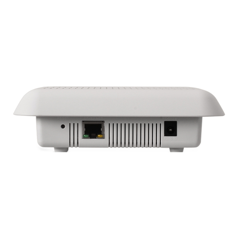
Simco-Ion IQ Power User manual

IQ Power Wireless Link 5201319 Rev B
IQ Power™ Wireless Link
INSTALLATION AND OPERATING INSTRUCTIONS

i
IQ Power Wireless Link 5201319 Rev B
TABLE OF CONTENTS
1. SAFETY WARNINGS ........................................................................... 1
2. DESCRIPTION .................................................................................. 2
3. SPECIFICATIONS ............................................................................... 3
4. INSTALLATION .................................................................................. 4
System Setup ......................................................................................................................4
Device Addressing ..............................................................................................................4
Control Station Wireless Configuration Set-up..................................................................5
Verify Bluetooth Communications .....................................................................................5
Mounting.............................................................................................................................6
System Configuration.........................................................................................................8
Electrical Connections ........................................................................................................9
Verify System Communications .......................................................................................10
5. OPERATION ....................................................................................10
6. MAINTENANCE ................................................................................11
7. TROUBLESHOOTING ..........................................................................12
8. PARTS AND ACCESSORIES...................................................................13
9. WARRANTY AND SERVICE ................................................................... 14

1
IQ Power Wireless Link 5201319 Rev B
1. SAFETY WARNINGS
PLEASE READ INSTRUCTIONS COMPLETELY BEFORE STARTING
INSTALLATION.
ALL INSTALLATION AND TROUBLESHOOTING OPERATIONS MUST
BE PERFORMED BY QUALIFIED TECHNICAL PERSONNEL.
This instruction manual uses symbols to identify dangerous situations as follows:
NOTE – Statements identified with NOTE indicate precautions necessary
to avoid potential equipment failure.
CAUTION – Statements identified with CAUTION indicate potential
safety hazards.
ATTENTION – Les déclarations identifiées avec ATTENTION indiquent
des dangers potentiels pour la sécurité.
WARNING – Statements identified with WARNING indicate potential
serious injury hazards.
AVERTISSEMENT – Les déclarations identifiées avec AVERTISSEMENT
indiquent un risque de blessures graves.
NOTE – This equipment must be correctly installed and properly
maintained. Adhere to the following notes for safe installation and operation:
1. Read instruction manual before installing or operating equipment.
2. Only qualified service personnel are to perform installation and repairs.
3. All equipment must be properly grounded, including the machine frame to which
the equipment is mounted.
4. Turn off input power to unit before connecting or disconnecting other equipment.
5. Do not operate system in close proximity to flammable liquids.
6. Do not use standard Ethernet cables with IQ Power Systems.
CAUTION – Electrical Shock Hazard
Disconnect input power to high voltage power supply before connecting
or disconnecting static neutralizing bar or performing any maintenance to
the system. Avoid touching static neutralizing bar when power supply is
energized.
ATTENTION – Risque De Choc Électrique
Couper l’alimentation à l’alimentation électrique de haute tension avant de
brancher ou de débrancher la barre de neutralisation statique ou d’effectuer
un entretien au système. Évitez de toucher la barre de neutralisation statique
lorsque l’alimentation électrique est sous tension.

2
IQ Power Wireless Link 5201319 Rev B
2. DESCRIPTION
Simco-Ion’s IQ Power Wireless Link Hub & Bluetooth Adapter provides a power
and communication hub for IQ Power and IQ Easy devices.
The Hub features 24 VDC input power via either an AC adapter or user supplied
24 VDC power. The AC adapter available with the Hub features a universal line
voltage input and will operate on 100 to 240 VAC, 50/60 Hz. The Hub can provide
power & communication for up to four IQ Power and four IQ Easy devices.
The Bluetooth Adapter provides wireless communication between Hub connected
devices and a Control Station; the Control Station must have a Bluetooth Adapter
connected. The wireless communication has an absolute maximum range of up to
61 meters (200 foot) with a typical range of 30.5 meters (100 foot) thus eliminating
the troublesome routing of cables.
With multi-drop installation, a single Bluetooth Adapter on a Control Station can
serve up to 4 Hubs equipped with Bluetooth Adapters.
Communication provided by the Bluetooth Adapter supports all data provided with
a typical cabled installation. With the connection to the Control Station, constant
monitoring is possible along with Warning / Fault relay output connections, a
Standby (STBY) input connector, Ethernet and a USB connector.
IQ Power system components use 8-conductor modular cable and RJ-45 connectors
for connection. IQ Power devices are typically supplied with a 7 foot modular cable
assembly. IQ Easy system components use 5-conductor cable with M12 connectors
for connection. Cables for either system are available by calling Simco-Ion customer
service (800) 203-3419 (refer to Section 8, Parts and Accessories).

3
IQ Power Wireless Link 5201319 Rev B
3. SPECIFICATIONS
Hub
Input Power 24 VDC, 3.75A, negative ground from AC adapter or user supplied
Connectors 4 IQ Power (RJ-45) One reserved for connection to Bluetooth Adapter;
4 IQ Easy (M12)
LED Indicator Green POWER
Operating Temp 50°C [122°F] max
Mounting (4) M5 [#10] hardware (not included)
Enclosure Steel, blue epoxy powder coated
Dimensions 78H x 85W x 40D mm [3.06”H x 3.35”W x 1.57”D]
Weight 240g [8.5 oz]
Bluetooth Adapter
Input Power/Comm IQ Power (RJ-45) connection to Hub/Control Station
LED Indicators 5 status lights
Operating Temp 50°C [122°F] max
Mounting (2) M5 [#10] hardware (not included)
Dimensions 116H x 48W x 18D mm [4.56”H x 1.88”W x 0.71”D]
Antenna 5 dBi, 210 mm [8.26”], fully positionable
AC Adapter
Type “Universal”desktop
Input Power 100-240 VAC 50/60 Hz
Output 24 VDC, 3.75A max
Dimensions 145L x 60W x 32H mm [5.71”L x 2.36”W x 1.26”H]
Weight 380g [13.4 oz]
Enclosure Thermoplastic, black
User Supplied Power
Input Power 24 VDC, 4A max, negative grounded

4
IQ Power Wireless Link 5201319 Rev B
4. INSTALLATION
NOTE – DO NOT USE standard Ethernet cables with IQ Power systems.
Avoid permanent equipment damage by using only Simco-Ion modular
cables. (Refer to Section 8, Parts and Accessories).
Figure 1. IQ Power Crossover Modular Cable (black) Wire Diagram
System Setup
NOTE – ADDRESS ALL IQ POWER AND IQ EASY DEVICES FIRST.
All devices must be individually addressed before connecting to the IQ
Power Hub.
The following steps must be taken in this order to properly install the Bluetooth
Adapters and Hubs:
• Address all IQ Power/IQ Easy devices individually before connecting to the
IQ Power Hub
• Configure the Control Station for wireless communications by setting to
Wireless or Legacy Mode if necessary
• Connect the Bluetooth Adapter labeled “for Control Station” to the Control
Station, connect the Bluetooth Adapter labeled “connect to Hub” to each IQ
Power Hub being used. Power up the devices and verify communications
• Mount all hardware
• Connect the IQ Power/IQ Easy devices to the IQ Power Hub
• Make all necessary electrical connections
• Confirm the devices are communicating on the Control Station home screen.
Device Addressing
NOTE – Devices must be addressed individually BEFORE connecting to
the IQ Power Hub

5
IQ Power Wireless Link 5201319 Rev B
Addressing of the IQ Power/IQ Easy devices allows for up to 10 devices to be set
and monitored by the Control Station. Follow the procedure below to address the
individual devices.
1. Plug the device to be addressed into the Control Station.
2. Once the device icon has appeared on the Control Station home screen, select
the device to open up the device page.
3. Tap on the page arrow until the screen with the device address setting appears.
4. Tap on the pencil next to the address setting to change the address. The
password screen will appear. Type in the password given to the Control Station,
then tap on the address number (1-10) to be assigned to the device connected
to the Control Station.
5. Once the address has been assigned, unplug the device from the Control
Station.
6. Repeat the process for each device being connected to the Control Station.
For more detailed instructions, please refer to the IQ Power Control Station
instruction manual.
Control Station Wireless Configuration Set-up
Before operation the Control Station must be set for wireless operation. If Wireless
Mode is available, set Control Station to Wireless Mode. If Wireless Mode is not
available, but Legacy Mode is available, set Control Station to Legacy Mode. If
neither Wireless or Legacy Mode is available, this step can be skipped.
1. The Control Station will start by displaying the Home Page. In the
upper portion of the display is an icon for System Settings (a gear). Tap
on the gear icon to open the System Settings page.
2. Tap on the pencil icon next to Wireless (or Legacy) Mode, see above.
3. Enter password.
4. Tap on Wireless (or Legacy) Mode, Yes to enable Wireless (or Legacy) Mode.
Wireless Mode sets digital communication to ensure reliable wireless operation.
Verify Bluetooth Communications
NOTE – If multiple adapters are used with the system, they must all have
the same “Matching No.” on their label. If the numbers do not match, the
system will not communicate properly.
Before mounting all hardware in its desired location, communications between the
Bluetooth Adapters must be confirmed. Connect the Bluetooth Adapter labeled “for
Control Station” to the control station using the supplied cable. Next, connect the
Bluetooth Adapter labeled “connect to Hub” to the IQ Power Hub. Apply power

6
IQ Power Wireless Link 5201319 Rev B
to the Control Station and IQ Power Hub. It may take 15-30 seconds for the
communications to be established. Verify that the lights are illuminated as follows:
1. Power indicator: lit (green)
2. Standby: not lit
3. Connect: lit (green)
NOTE – In systems with multiple Hubs, if all Hubs are not connected the
Control Station Bluetooth Adapter Connect light will flash (green).
4. Serial-Tx / Serial-Rx flicker (green) to indicate operation.
At the Control Station Serial-TX always flickers, Serial-Rx flickers (faintly)
when a device is connected to a Hub.
At the Hub Serial-Rx always flickers, Serial-Tx flickers (faintly) when a device is
connected to the Hub
Once communications have been verified, the hardware can be mounted in its
desired location.
Mounting
Install the Hub at a convenient place that keeps total overall cable length to a
minimum.
The black modular cable used to connect IQ Power devices to the Hub is available
in a variety of lengths and may be re-terminated by the user. Cables must be
8-conductor modular cables with RJ-45 connectors wired “crossover” (reference
color: black, Figure 1).
Cables used to connect IQ Easy devices are available in a variety of standard lengths
with straight M12 connectors at the Hub end and with a straight or right angle M12
connector at the IQ Easy device end.
Secure Hub to mounting surface using M5 [#10] hardware (not included).
Install the Bluetooth Adapters at convenient places near the Control Station and
Hub. Use the provided metal brackets and hardware.
The adapter located at the Control Station must be labeled “IQ Power Bluetooth
Adapter (for Control Station)”.
The adapter located at the Hub must be labeled “IQ Power Bluetooth Adapter
(connect to Hub)”.
The Bluetooth Adapter uses IQ Power style black modular cable (see above). The
Bluetooth Adapter should be mounted in an area relatively free of metal framework
or metal that would attenuate the Bluetooth wireless signal. The absolute maximum
effective range for the Bluetooth Adapters is approximately 61 meters (200 foot).
This maximum can only be achieved with a clear line of site and no metal that
could attenuate the signal. The typical working range of the adapters is 30.5 meters

7
IQ Power Wireless Link 5201319 Rev B
(100 foot). Many environmental variables impact estimated wireless distance
range, but the Bluetooth Adapter is designed with a high-gain antenna to optimize
performance. To ensure clear, uninterrupted communication, provide a line-of-sight
between Bluetooth Adapters that is also relatively free of metal framework or metal
that would attenuate the signal.
IQ Power Hub
IQ Power Wireless Link
Figure 2. IQ Power Hub & Bluetooth Adapter Dimensions

8
IQ Power Wireless Link 5201319 Rev B
System Configuration
The IQ Power Hub with Bluetooth Adapter serves to distribute power and provide
communications over a small area for IQ Power/IQ Easy devices. Power for the
devices is provided by either an available AC adapter or user provided 24 VDC.
Communication is enabled with Bluetooth wireless connection to the Control
Station with the devices behaving the same as they would if hard wired to the
Control Station.
The IQ Power Bluetooth Adapter connected to the Control Station must be labeled
“(for Control Station)”.
The IQ Power Bluetooth Adapter connected to any Hubs must be labeled “(connect
to Hub)”.
IQ Power HL
Power Supply
Intrinsic
Safety
Barriers
IQ Power HL
Sensor Interface
IQ Power HL Sensor
Conduit Seals
and Conduit
IQ Power HL Static Bar
IQ Power Static Bar
IQ Power BPS
AC Adapter
24 VDC
+24 VDC
IQ Easy Sensor Bar
IQ Easy Static Bar
IQ Easy LP Static Bar
IQ Power
Hub
IQ Power
Hub
Bluetooth Data Link
IQ Power Wireless Link -
Bluetooth Adapter
connected to Hub
Ground
User Supplied Power
Hazardous Area Location
IQ Power
Control Station
IQ Power Wireless Link -
Bluetooth Adapter
connected to
Control Station
Bluetooth Data Link
IQ Power Wireless Link -
Bluetooth Adapter
connected to Hub
Figure 3. IQ Power Hub & Bluetooth Adapter Connections

9
IQ Power Wireless Link 5201319 Rev B
Electrical Connections
Connect Ground: Ground IQ Power Hub by connecting ground lead between
ground terminal on flange of the hub and a good electrical machine ground.
Connect AC Adapter: Connect AC Adapter (if used, AC adapter is not required
if the Hub is connected to user 24 VDC power). Route low voltage wire clear of
moving machine parts and protect it from abrasion. Secure using nylon wire ties
(not supplied). Do not over tighten. Insert barrel connector into power connector
on Hub. Hand tighten barrel connector nut to secure.
Connect line voltage to input side of AC adapter. The AC adapter is a universal
input type that accepts line voltage from 100 to 240 VAC 50/60 Hz. The AC
adapter line voltage connector accepts a line cord with an IEC 320 connector
(supplied). The line cord also provides electrical ground to the AC adapter. Check
electrical ground integrity in the line voltage receptacle used for the AC adapter.
This ground must not be defeated.
Connect User Supplied Power: Connect user supplied power (if used). In cases
where the user does not want to use the AC adapter but wants to supply 24 VDC
power to the IQ Power Hub, user supplied 24 VDC power may be applied via a
removable 2-position pluggable header (3.81 mm / .150” centers). The connector
accepts up to 16 AWG wire with a strip length of 7 mm [1/4”]. To install wires into
the connector, push the stripped wire fully into the square hole on the connector and
tighten securely with a small flat-blade screwdriver. Connection should be made as
shown below:
The user power connector is adjacent the connector for the AC adapter.
1 2
_
+
Figure 4. IQ Power Hub User Power Connection
Power supplied must be 24 VDC with a grounded negative polarity. Power supplied
must have adequate current available to power all components on the system
(maximum 4A). Input power should be appropriately fused for safety purposes.
Connect the Bluetooth Adapter: Cables used to connect the Bluetooth Adapter
are standard IQ Power modular cables (ref. Fig. 1). Where the Bluetooth Adapter
is connected to the IQ Power Hub, connect the cable to any available RJ-45 socket,
1 through 4. Where the Bluetooth Adapter is connected to the IQ Power Control
Station, connect the cable to any available Power & Comm RJ-45 socket, 1 through
10.

10
IQ Power Wireless Link 5201319 Rev B
Connect IQ Power and IQ Easy Devices: IQ Power devices connect to available
RJ-45 sockets, 1 through 4 on the Hub. IQ Easy devices connect to available M12
Connectors DEV1 through DEV 4 on the Hub.
The IQ Power Hub with Bluetooth Adapter is an extension of the Control Station.
As such, connection procedures, limitations, and device addressing should be carried
out as described in the IQ Power Control Station instruction manual and in the
Addressing section above.
Verify System Communications
Once all previous steps have been performed, devices can be wired and powered up
one at a time. Communication to the Control Station will need to be verified. To
verify communication, observe the home screen of the Control Station. If the device
communicates properly, the device should have an icon on the home screen. If the
device does not show up, follow the troubleshooting guide in this manual, or the
manual provided with the missing device. Repeat until all devices are connected and
communicating.
5. OPERATION
The Hub provides power and communication to all IQ Power and IQ Easy devices
connected to it and to the Bluetooth Adapter. The Hub has a green POWER LED
which should be lit during operation.
The Bluetooth Adapter provides wireless communication between connected devices
and the Control Station.
Before using the devices with the Bluetooth Adapter, each device must be given an
address by connecting it directly to the control station.
1. Plug the device to be addressed into the Control Station.
2. Once the device icon has appeared on the Control Station home screen, select
the device to open up the device page.
3. Tap on the page arrow until the screen with the device address setting appears.
4. Tap on the pencil next to the address setting to change the address. The
password screen will appear. Type in the password given to the Control Station,
then tap on the address number (1-10) to be assigned to the device connected
to the Control Station.
5. Once the address has been assigned, unplug the device from the Control
Station.
6. Repeat the process for each device being connected to the Control Station.
NOTE – Only 10 device address can be assigned to a Control Station. If
more devices are required, an additional Control Station will be needed.

11
IQ Power Wireless Link 5201319 Rev B
For more detailed instructions on connecting devices to the Control Station, please
refer to the instruction manual provided with the Control Station.
Once the devices have been addressed and disconnected from the Control Station,
connect the Bluetooth Adapter to the Control Station using the provided cable.
Check to ensure that the power switch on the Bluetooth Adapter is in the “On”
position. It should come from the factory in this state, and should not be switched
off at any time. Connect the Bluetooth Adapter to each Hub being used. Apply
power to the Hub and check for communication between the adapters. The
indicators on the adapters will light as follows:
1. Power indicator: lit (green)
2. Standby: not lit
3. Connect: lit (green)
NOTE – In systems with multiple Hubs, if all Hubs are not connected the
Control Station Bluetooth Adapter Connect light will flash (green).
4. Serial-Tx / Serial-Rx flicker (green) to indicate operation.
At the Control Station Serial-TX always flickers, Serial-Rx flickers (faintly)
when a device is connected to a Hub.
At the Hub Serial-Rx always flickers, Serial-Tx flickers (faintly) when a device is
connected to the Hub.
NOTE – It may take 15 to 30 seconds for a device to begin communicating.
Now that communications between the hub(s) and the Control Station have been
established, the devices can be plugged into the hub(s). The device icons should
begin to appear on the Control Station home screen with an incrementing timer.
Devices may take 15-30 seconds to appear.
6. MAINTENANCE
The Hub and Bluetooth Adapter do not require regular periodic maintenance.
Occasional checking to ensure proper electrical connections, including that the
antenna is secure, may be made.

12
IQ Power Wireless Link 5201319 Rev B
7. TROUBLESHOOTING
NOTE – Only qualified service personnel are to perform troubleshooting
tasks.
PROBLEM CAUSE SOLUTION
Power LED not
illuminated on
Hub
24 VDC not applied to Hub Make corrections to ensure 24 VDC is applied
to Hub
Line voltage not supplied to
AC adapter Check line voltage and connections
A device connected to Hub
drawing too much current.
Disconnect devices, one-by-one, from Hub to
see if power is restored
Digital
communication
has failed
Bluetooth Adapter needs reset
Remove power from Bluetooth Adapters,
wait 10 seconds, re-apply power to
Bluetooth Adapters
Poor electrical connections Check connections of device cables at device
and Hub. Check condition of cables
Power switch on the Adapter
is in the “Off” position Switch to the “On” position
“Matching No.” on adapters
are not the same
Find adapters with the same “Matching No.”
to complete system
Bluetooth Adapters fail to
connect
Reset adapters by removing and re-applying
power. If connection is not established,
contact factory

13
IQ Power Wireless Link 5201319 Rev B
8. PARTS AND ACCESSORIES
Part Description Part Number
IQ Power Hub 4110855
IQ Power Hub AC Adapter 4110867
Line Cord, North American/Japan 120/100 VAC 4106272
Line Cord, North American 230 VAC 4106274
24VDC Connector Kit, User Power In 5051990
IQ Power Bluetooth Adapter Contact Factory
Bluetooth Antenna, 7.7”long, 5dBi 4591193
Modular Cable (RJ-45 to RJ-45, IQ Power 8-conductor, crossover wired) for use
between Control Station and IQ Power BPS / HL / RDM“COMM 1”
DO NOT USE Standard Ethernet Cables (see Figure 1)
0.91 meter [3 foot] black
2.13 meter [7 foot] black
4.27 meter [14 foot] black
7.62 meter [25 foot] black
15.24 meter [50 foot] black
22.86 meter [75 foot] black
30.48 meter [100 foot] black
4520785
4520786
4520787
4520784
4520844
4520845
4520832
Cable (RJ-45 to straight M12 connector)
IQ Power BPS to IQ Easy Sensor Bar with straight connector at Sensor Bar end
4.57 meter [15 foot] Straight M12 Connector
9.14 meter [30 foot] Straight M12 Connector
5051840
5051844
Cable (RJ-45 to right angle M12 connector)
IQ Power BPS to IQ Easy Sensor Bar with right angle connector at Sensor Bar end
4.57 meter [15 foot] Right Angle M12 Connector
9.14 meter [30 foot] Right Angle M12 Connector
5051841
5051845
Cable (IQ Easy M12 connectors at both ends) for use between Control Station and
IQ Easy with straight connector at IQ Easy device end
5 meter [16.4 foot] Straight / Straight M12 Connector
10 meter [32.8 foot] Straight / Straight M12 Connector
20 meter [65.6 foot] Straight / Straight M12 Connector
30 meter [98.4 foot] Straight / Straight M12 Connector
5051791
5051792
5051793
5051794
Cable (IQ Easy M12 connectors at both ends) for use between Control Station and
IQ Easy with right angle connector at IQ Easy device end
5 meter [16.4 foot] Straight / Right Angle M12 Connector
10 meter [32.8 foot] Straight / Right Angle M12 Connector
20 meter [65.6 foot] Straight / Right Angle M12 Connector
30 meter [98.4 foot] Straight / Right Angle M12 Connector
5051796
5051797
5051798
5051799
Bluetooth Adapter Mounting Bracket 4750063

IQ Power Wireless Link 5201319 Rev B
9. WARRANTY AND SERVICE
This product has been carefully tested at the factory and is warranted to be free from
any defects in materials or workmanship. Simco Ion will, under this warranty, repair
or replace any equipment which proves, upon our examination, to have become
defective within one year from the date of purchase.
The equipment being returned under warranty should be shipped by the purchaser
to Simco-Ion, 2257 North Penn Road, Hatfield, PA 19440, transportation prepaid
and insured for its replacement cost. Prior to returning any goods for any reason,
contact Simco-Ion Customer Service at 215-822-6401 for a Return Authorization
Number (RMA). This number must accompany all returned items.
This warranty does not apply when the equipment has been tampered with, misused,
improperly installed, altered, has received damage through abuse, carelessness,
accident, connection to improper line voltage, or has been serviced by anyone other
than an authorized factory representative.
The warranty does not apply when Simco-Ion parts and equipment have been
energized by other than the appropriate Simco-Ion power supply or generator,
or when a Simco- Ion power supply or generator has been used to energize other
than Simco-Ion parts and equipment. Simco-Ion makes no warranty, expressed or
implied, nor accepts any obligation, liabilities, or responsibility in connection with
the use of this product other than the repair or replacement of parts stated herein.
Information in this publication supersedes that in all previous published material.
Specifications are subject to change without notice.
Simco-Ion
2257 North Penn Road
Hatfield, PA 19440
(215) 822-6401
(800) 203-3419
www.simco-ion.com
© 2021 Simco-Ion. Printed in the U.S.A.
Other manuals for IQ Power
1
Table of contents
Popular Network Router manuals by other brands
Cosmote
Cosmote Speedport Plus 2 instruction manual
ORiNG
ORiNG TGAR-1062-M12-3G Quick installation guide
Compex
Compex NetPassage 18A quick start guide
Linksys
Linksys WRT320N - Wireless-N Gigabit Router Wireless user guide
Unitronics
Unitronics V1210-T20BJ installation guide
D-Link
D-Link DIR-857 Quick installation guide
