manuals.online logo
Brands
  1. Home
  2. •
  3. Brands
  4. •
  5. Sime
  6. •
  7. Boiler
  8. •
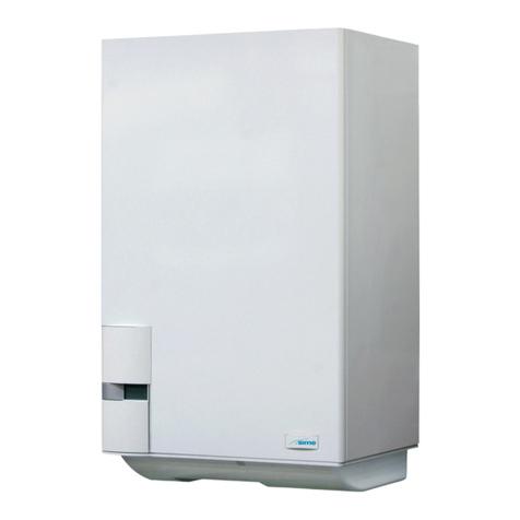
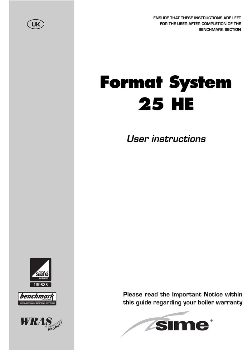
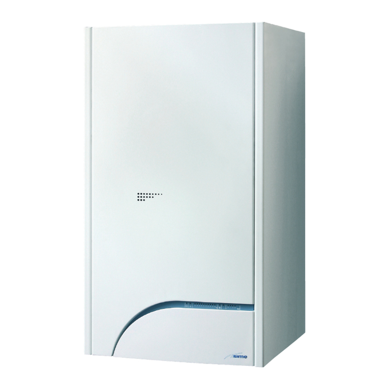
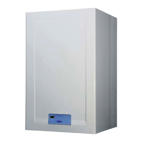
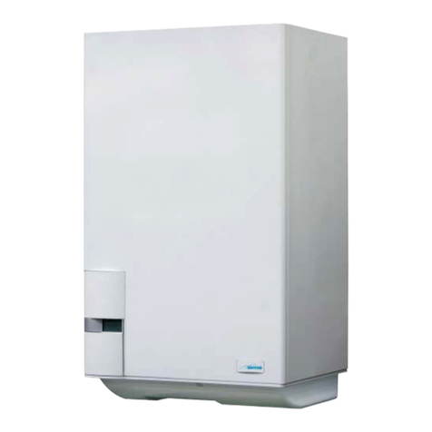
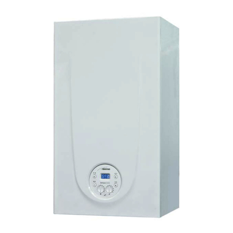
  9. Sime MURELLE HE ErP Series User manual

Sime MURELLE HE ErP Series User manual

MURELLE HE ErP
Fonderie SIME S.p.A C od. 6322859B - 03/2017
ENG
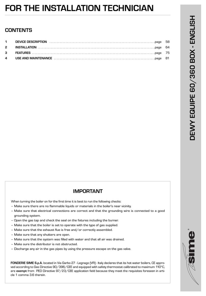
INSTALLER INSTRUCTIONS
CONTENTS
1  DESCRIPTION OF THE BOILER .......................................................................................................... pag. 76
2  INSTALLATION ................................................................................................................................... pag. 81
3  CHARACTERISTICS ............................................................................................................................ pag. 94
4  USE AND MAINTENANCE .................................................................................................................. pag. 101
IMPORTANT
When carrying out commissioning of the boiler, you are highly recommended to perform the following
checks:
–
Make sure that there are no liquids or inflammable materials in the immediate vicinity of the boiler.
– Make sure that the electrical connections have been made correctly and that the earth wire is con-
nected to a good earthing system.
– Open the gas tap and check the soundness of the connections, including that of the burner.
– Make sure that the boiler is set for operation for the type of gas supplied.
– Check that the flue pipe for the outlet of the products of the combustion is unobstructed and has
been properly installed.
– Make sure that any shutoff valves are open.
– Make sure that the system is charged with water and is thoroughly vented.
– Check that the circulating pump is not locked.
– Purge the system, bleeding off the air present in the gas pipe by operating the pressure relief valve
on the gas valve inlet.
–
The installer must provide the user with instruction in operation of the boiler and safety devices and
hand over the instruction booklet to the user.
MURELLE HE ErP - ENGLISH
CONFORMITY
Our Company declares that MURELLE HE ErP boilers comply with the essential requirements of the fol-
lowing directives:
- Boiler Efficiency Directive 92/42/EEC
- Gas Appliances Directive 2009/142/EC
- Electromagnetic Compatibility Directive 2014/30/UE
- Low Voltage Directive 2014/35/UE
- Ecodesign Directive 2009/125/EC
- Regulation (EU) N. 813/2013 - 811/2013
76
1.1   INTRODUCTION
MURELLE HE ErP are premixed gas con-
densation thermal modules that employ
a microprocessor-based technology to
control and manage all the functions.
For optimum installation and operation,
always follow the instructions provided in
this manual.
1  DESCRIPTION OF THE BOILER
385
65 65 65 65 =
=
=
=
92,5
125
350
42,5
450
170
60/100
13 5
125
125
70065
760
215
15
Fig. 1
FIXTURES
R C.H. return G 3/4” (UNI - ISO 228/1)
M C.H. flow G 3/4” (UNI - ISO 228/1)
G Gas connection G 3/4” (UNI - ISO 228/1)
R3 D.H.W. tank return G 3/4” (UNI - ISO 228/1)
M2 D.H.W. tank output G 3/4” (UNI - ISO 228/1)
S3 Condensation outlet ø 25
1.2  DIMENSIONS
1.2.1  Murelle HE 12 - 25 - 30 - 35 T ErP (fig. 1)
ATTENTION:
The “T” version is designed for the connection of a remote boiler, to
use it as a boiler ONLY FOR HEATING it is necessary:
- to disconnect the D.H.W. sensor (SB)
- set the PAR 2 to 4.
All modules are designed to be used by qualified technical per-
sonnel.
77
ES
PT
ENG
1.2.2  Murelle HE 25 - 30 - 35 ErP (fig. 1/a)
S3
65 700 125
60/100
15
760
213
92
65 65 65 65 =
=
=
=385
13 5
170
450
123
350
42,5
Fig. 1/a
FIXTURES
R C.H. return G 3/4” (UNI - ISO 228/1)
M C.H. flow G 3/4” (UNI - ISO 228/1)
G Gas connection G 3/4” (UNI - ISO 228/1)
E D.H.W. inlet G 1/2” (UNI - ISO 228/1)
U D.H.W. outlet G 1/2” (UNI - ISO 228/1)
S3 Condensation outlet ø 25
78
MURELLE HE  25 ErP  30 ErP  35 ErP  12 T ErP  25 T ErP  30 T ErP  35 T ErP
Heat output
Nominal (80-60°C) (Pn max) kW 23.9 28.9 34.1 11.7 23.9 28.9 34.1
Nominal (50-30°C) (Pn max) kW 26.2 31.6 37.2 12.8 26.2 31.6 37.2
Reduced G20 (80-60°C) (Pn min) kW 4.7 5.9 7.9 2.8 4.7 5.9 7.9
Reduced G20 (50-30°C) (Pn min) kW 5.4 6.6 8.8 3.2 5.4 6.6 8.8
Reduced G31 (80-60°C) (Pn min) kW 7.5 7.6 8.7 3.7 7.5 7.6 8.7
Reduced G31 (50-30°C) (Pn min) kW 8.5 8.5 9.6 4.2 8.5 8.5 9.6
Heat input (*)
Nominal (Qn max - Qnw max) kW 24.5 29.5 34.8 12.0 24.5 29.5 34.8
Reduced G20/G31 (Qn min - Qnw min) kW 5.0/8.0 6.2/8.0 8.2/9.0 3.0/4.0 5.0/8.0 6.2/8.0 8.2/9.0
Min./Max. useful yield (80-60°C) % 94/97.6 95/98 96/98 94/97.5 94/97.6 95/98 96/98
Min./Max. useful yield (50-30°C) % 107/107 107/107 107/107 107/107 107/107 107/107 107/107
Useful yield at 30% of the load (40-30°C) % 107,8 107,7 106,8 107,2 107,8 107,7 106,8
Losses after shutdown to 50°C (EN 15502)  W 85 89 90 78 90 95 98
Supply voltage V-Hz 230-50 230-50 230-50 230-50 230-50 230-50 230-50
Adsorbed power consumption (Qn max) W 84 83 93 66 84 83 93
Adsorbed power consumption (Qn min) W 55 55 56 51 55 55 56
Electrical protection grade IP X4D X4D X4D X4D X4D X4D X4D
Energy efficiency
Seasonal energy efficiency class of the heating system A A A A A A A
Seasonal energy efficiency of the heating system % 92 92 91 91 92 92 91
Sound power of the heating system dB (A) 55 53 54 48 55 53 54
D.H.W. energy efficiency class A A A -- -- -- --
D.H.W. energy efficiency % 85 86 85 -- -- -- --
D.H.W. load profile declared XL XL XL -- -- -- --
C.H. setting range °C 20/80 20/80 20/80 20/80 20/80 20/80 20/80
Water content boiler l 4.9 5.5 6.0 4.4 5.0 5.6 6.1
Maximum water head (PMS) bar 3 3 3 3 3 3 3
Maximum temperature (T max) °C 85 85 85 85 85 85 85
Capacity/Press. of the heating expansion vessel  l/bar (kPa) 8/1 (98) 10/1 (98) 10/1 (98) 8/1 (98) 8/1 (98) 10/1 (98) 10/1 (98)
D.H.W. setting range °C 10/65 10/65 10/65 -- -- -- --
D.H.W. flow rate (EN 13203) l/min 11.2 13.6 16.1 -- -- -- --
Continuous D.H.W. flow rate (∆t 30°C) l/min 11.3 13.8 16.3 -- -- -- --
Minimum D.H.W. flow rate l/min 2 2 2 -- -- -- --
D.H.W. pressure min./max. (PMW) bar (kPa)
0.2/7.0 (19.6/686)
0.2/7.0 (19.6/686)
0.2/7.0 (19.6/686)
-- -- -- --
D.H.W. pressure min. nom. power bar (kPa) 0.5 (49) 0.65 (63.7) 0.8 (78.4) -- -- -- --
Exhaust fumes temperature at max. flow rate (80-60°C) °C 70 70 70 70 70 70 70
Exhaust fumes temperature at min. flow rate (80-60°C) °C 65 65 65 65 65 65 65
Exhaust fumes temperature at max. flow rate (50-30°C) °C 40 40 40 40 40 40 40
Exhaust fumes temperature at min. flow rate (50-30°C) °C 35 35 35 35 35 35 35
Smokes flow minimum g/s 2.50 3.06 3.89 1.39 2.50 3.06 3.89
Smokes flow maximum g/s 11.67 13.89 16.67 5.84 11.67 13.89 16.67
CO2 at max./min. flow rate (G20) % 9.0/9.0 9.0/9.0 9.0/9.0 9.0/9.0 9.0/9.0 9.0/9.0 9.0/9.0
CO2 at max./min. flow rate (G31) % 10.0/10.0 10.0/10.0 10.0/10.0 10.0/10.0 10.0/10.0 10.0/10.0 10.0/10.0
NOx measured 
(EN 15502-1:2015)
mg/kWh 23 17 25 22 23 17 25
PIN number 1312BU5312
Category II2H3P
Type B23P - B53P - C13 - C33 - C43 - C53 - C83
NOx emission class 
(EN 15502-1:2015)
6 (‹ 56 mg/kWh)
Weight when empty kg 43,4 45,0 46,6 41,2 42,4 44,0 45,2
Main burner nozzle
Quantity nozzles n° 2 2 2 1 2 2 2
G20 nozzle diameter diversified ø 2.4/3.3 2.8/3.8 3.5/4.0 3.3 2.4/3.3 2.8/3.8 3.5/4.0
G31 nozzle diameter diversified ø 1.9/2.6 2.2/2.9 2.8/3.0 2.6 1.9/2.6 2.2/2.9 2.8/3.0
Gas consumption at max./min.  flow rate (G20) m3/h 2.59/0.53 3.12/0.66 3.68/0.87 1.27/0.32 2.59/0.53 3.12/0.66 3.68/0.87
Gas consumption at max./min.  flow rate (G31) kg/h 1.90/0.62 2.29/0.62 2.70/0.70 0.93/0.62 1.90/0.62 2.29/0.62 2.70/0.70
Gas supply pressure (G20/G31) mbar (kPa)
20/37 (1.96/3.63) 20/37 (1.96/3.63) 20/37 (1.96/3.63) 20/37 (1.96/3.63) 20/37 (1.96/3.63) 20/37 (1.96/3.63) 20/37 (1.96/3.63)
(*) Heat input of the heating system measured using lower heating value (LHV)
1.3  TECHNICAL FEATURES
79
ES
PT
ENG
1.4  FUNCTIONAL DIAGRAM (fig. 2)
NON FORNITO
Fig. 2
NON FORNITO
MURELLE HE 12 T - 25 T - 30 T - 35 T ErP
MURELLE HE 25 - 30 - 35 ErP
NOT PROVIDED
KEY
1 Fan
2 Limit thermostat
3 Primary exchanger
4 Gas valve
5 D.H.W. exchanger
6 Aqua Guard Filter System
7 C.H. sensor (SM)
8 Safety thermostat 100°C
9 Diverter valve
10 Pump high efficiency
12 D.H.W. sensor (SS/SB)
13 D.H.W. flowmeter
14 Hot water inlet filter
15 Loading
16 3 BAR safety valve
17 Pressure transducer
19 Boiler discharge
20 Expansion vessel
21 Condensate drain tap
23 D.H.W. cock (optional)
24 Gas cock (optional)
25 C.H. flow cock (optional)
26 C.H. return cock (optional)
CONNECTIONS
R C.H. return
M C.H. flow
G Gas connection
E D.H.W. inlet
U D.H.W. outlet
S3 Condensation outlet
80
Fig. 3
KEY
1 Control panel
2 Aqua Guard Filter System
3 Ignition transformer
4 Air pressure tap
6 Safety thermostat
7 C.H. sensor (SM)
8 Ignition electrode
9 Primary exchanger
10 Sensor fumes (SF)
11 Suction/discharge fitting
12 Expansion vessel
13 Detection electrode
14 Fan
16 Diverter valve
17 Pump high efficiency
18 Coupling protection
1.5  MAIN COMPONENTS (fig. 3)
MODEL
SERIAL NUMBER
YEAR OF CONSTRUCTION
WATER CONTENT IN BOILER
HEAT INPUT MAX
HEAT OUTPUT MAX (80-60°C)
HEAT OUTPUT MAX (50-30°C)
MAX OPERATING PRESSURE
CONTENTS D.H.W.
HEAT INPUT MAX D.H.W.
MAX OPERATING PRESSURE D.H.W.
D.H.W. FLOW RATE
POWER SUPPLY
MAX POWER ABSORBED
COUNTRIES OF DESTINATION
CATEGORY
TYPE
CODE
DIRECTIVE OF REFERENCE
PIN NUMBER
HEAT INPUT MIN
HEAT OUTPUT MIN (80-60°C)
HEAT OUTPUT MIN (50-30°C)
MAX OPERATING PRESSURE
HEAT INPUT MIN D.H.W.
MAX OPERATING PRESSURE D.H.W.
ELECTRICAL PROTECTION GRADE
NOx CLASS
CODE GAS COUNCIL NUMBER (UK)
CERTIFICATION WRAS (UK)
TYPE OF GAS
GAS SUPPLY PRESSURE
CLASSIFICATIONS
Fig. 3/a
1.6  TECHNICAL DATA PLATE (fig. 3/a)
81
ES
PT
ENG
The boiler must be installed in a fixed loca-
tion and only by specialized and qualified
firms in compliance with all instructions
contained in this manual. Furthermore, the
installation must be in accordance with cur-
rent standards and regulations.
2.1  INSTALLATION
– Boilers can be installed in all domestic
environments without any whatsoever
limit in terms of location and comburent
air supply.
– These boilers can also be installed in par-
tially covered areas, as per EN 15502, with
a maximum ambient temperature of 60°C
and a minimum ambient temperature of
-5°C. It is generally advisable to install
the boilers below weathered roofs, on the
balcony or in a protected niche, to protect
them from exposure to weathering agents
(rain, hail and snow). All boilers provide a
standard antifreeze function.
2.1.1 Anti-freeze function
The boilers are equipped with anti-freeze
function which activates the pumps and
the burner when the temperature of the
water contained inside the appliance drops
to below 6°C. The anti-freeze function is
ensured, however, only if:
- the boiler is correctly connected to the
gas and electricity supply circuits;
- the boiler is constantly fed;
- the boiler ignition is not blocked;
- the essential components of the boiler are
all in working order.
In these conditions the boiler is protected
against frost down to an environmental tem-
perature of -5°C.
ATTENTION: In the case of installation in a 
place where the temperature drops below 
0°C,  the  connection  pipes  must  be  pro-
tected. 
2.2 COMPLEMENTARY ACCESSORIES
To simplify connections to the hydraulic and
gas supplies, it is also possible to use the
following accessories:
– Mounting plate, code 8081220
– Kit with bends, code 8075423
– Kit with faucets, code 8091806
– Kit with faucets boiler T, code 8091820
– Kit for the replacement of wall-mounting
assemblies of other manufacturers, code
8093900
– Solar kit for the instantaneous, code
8105101, in coupling to kit INSOL
– Mixed area kit ZONA MIX, code 8092234
– Solar kit INSOL only for heating boilers,
code 8092235
– Antifreeze heaters kit -15°C, code
8089806.
For detailed information on the assembly
of fittings, see the instructions contained
in the box.
2.3  CONNECTING UP SYSTEM
To protect the heat system from damaging
corrosion, incrustation or deposits, befo-
re installation it is extremely important to
clean the system using suitable products
such as, for example, Sentinel  X300  (new 
system),  X400  and  X800  (old  system)  or 
Fernox  cleaner  F3. Complete instructions
are provided with the products but, for fur-
ther information, you may directly contact
SENTINEL PERFORMANCE SOLUTIONS LTD
or FERNOX COOKSON ELECTRONICS.
For long-term protection agains corrosion
and deposits, the use of inhibitors such as
Sentinel  X100  or  Fernox  protector  F1 is
recommended after cleaning the system. It
is important to check the concentration of
the inhibitor after each system modifica-
tion and during maintenance following the
manufacturer’s instructions (specific tests
are available at your dealer). The safety
valve drain must be connected to a collec-
tion funnel to collect any discharge during
interventions. If the heating system is on a
higher floor than the boiler, install the on/off
taps supplied in kit optional on the heating
system delivery/return pipes.
WARNING: Failure to clean the heat system 
or add an adequate inhibitor invalidates the 
device’s warranty.
Gas connections must be made in accordan-
ce with current standards and regulations.
When dimensioning gas pipes from the
meter to the module, both capacity volume
(consumption) in m
3
/h and gas density must
be taken into account.
The sections of the piping making up the
system must be such as to guarantee a sup-
ply of gas sufficient to cover the maximum
demand, limiting pressure loss between the
gas meter and any apparatus being used to
not greater than:
– 1.0 mbar for family II gases (natural gas);
– 2.0 mbar for family III gases (butane or
propane).
An adhesive data plate is sticked inside the
front panel; it contains all the technical data
identifying the boiler and the type of gas for
which the boiler is arranged.
2.3.1  Connection of condensation 
  water trap
The drip board and its water trap must be
connected to a civil drain through a pipe with
a slope of at least 5 mm per metre to ensure
drainage of condensation water.
The  plastic  pipes  normally  used  for  civil 
drains  are  the  only  type  of  pipe  which  is 
appropriate for  conveying  condensation to 
the building’s sewer pipes.
2.3.2  Filter on the gas pipe
The gas valve is supplied ex factory with an
inlet filter, which, however, is not adequate
to entrap all the impurities in the gas or in
gas main pipes.
To prevent malfunctioning of the valve, or in
certain cases even to cut out the safety devi-
ce with which the valve is equipped, install
an adequate filter on the gas pipe.
2.4  SYSTEM FILLING (fig. 4)
Filling of the boiler and the system is done by
the system filling (11). The charge pressure,
Fig. 4
2  INSTALLATION
KEY
1 Diverter valve (VD)
2 D.H.W. sensor (SS)
3 D.H.W. exchanger with plates
4 Water pressure transducer (TPA)
5 Air release vent
6 Pump high efficiency (PI)
7 Boiler discharge
8 3 BAR safety valve
9 D.H.W. filter
10 D.H.W. flowmeter sensor
11 System loading
82
with the system cold, must be between 1 
and 1.5 bar.
NB:  The  “T”  versions  the  loading  is  done 
by  loading  tap  externally  mounted  by  the 
installer.
2.4.1  System draining (fig. 4)
To drain the system, turn off the boiler and
use the discharge valve (7).
2.5  INSTALLATION OF 
  COAXIAL DUCT
  ø 60/100 - ø 80/125 (fig. 6)
The axial suction and discharge pipes are
supplied in a special kit (that can be pur-
chased separately) along with assembly
instructions.
The diagrams of fig. 6 illustrate some exam-
ples of different types of discharge modali-
ties allowed and the maximum lengths that
can be reached.
2.6  INSTALLATION OF SEPARATE    
  DUCTS ø 80 - ø 60 (figg. 7-8)
The kit with dedicated pipes enables to
separate the exhaust fumes pipes from the
air suction pipes (Fig. 7):
- The kit with dedicated ø 80 pipes, code.
8089912, includes a SUCTION DIAPHRAGM 
THAT IS NOT used for these models. To be
able to use the air tap, cut its base with a
tool (A) and assemble it (B).
- The kits with dedicated ø 60 pipes, code
8089913, include a suction collar that
replaces the boiler collar (C).
It is now possible to insert an expansion or
bend in polypropylene without gaskets or
sealant.
The  maximum  overall  length,  resulting 
from the sum of all the suction and dischar-
ge pipes, is determined by the load losses 
of  the  single  connected  accessories  and 
should not exceed 10 mm H2O (version 12) - 
15 mm H2O (version 25-30-35) (ATTENTION: 
the  total  length  of  each  pipe  should  not 
exceed 25 m, even if the total loss is below 
the maximum applicable loss.)
See Table 1-1/a for information on the load
losses of single accessories and the exam-
ple of Fig. 8 for information on how to calcu-
late load losses.
C33
6
5
3
2
C43
3
42
x
y
x + y = L (m)
H (m)
C13
1
2
1
L (m)
2
Fig. 6
IMPORTANT:
-  The  insertion  of  each  additional  90° 
bend with a diameter of  60/100 reduces 
the available section by 1.5 meters.
-  The  insertion  of  each  additional  90° 
bend with a diameter of 80/125 reduces 
the available section by 2 meters.
-  Each  additional  45°  curve  installed 
reduces  the  available  length  by  1.0 
metres.
- During assembly it is important to make 
sure that the kit with axial pipes.  (1) is 
positioned horizontally.
NOTE
Before  connecting  accessories,  it  is 
always advisable to lubricate the internal 
part of the gaskets with silicon products. 
Avoid using oils and greases.
Model Length of pipe Length of pipe
  ø 60/100  ø 80/125
  L            H     L            H
    Min  Max    Min  Max
12 T 6 m 1.3 m 8 m 12 m 1.2 m 15 m
25 / 25 T 6 m 1.3 m 8 m 12 m 1.2 m 15 m
30 / 30 T 5 m 1.3 m 7 m 10 m 1.2 m 13 m
35 / 35 T 4 m 1.3 m 6 m 8 m 1.2 m 11 m
LIST OF ø 60/100 ACCESSORIES
1 Coaxial duct kit code 8096250
2a Extension L. 1000 code 8096150
2b Extension L. 500 code 8096151
3 Vertical extension L. 140 with coupling code 8086950
4a Additional 90° curve code 8095850
4b Additional 45° curve code 8095950
5 Tile for joint code 8091300
6 Terminal for roof exit L. 1285 code 8091205
LIST OF ø 80/125 ACCESSORIES
1 Coaxial duct kit code 8096253
2a Extension L. 1000 code 8096171
2b Extension L. 500 code 8096170
3 Adapter for ø 80/125 code 8093150
4a Additional 90° curve code 8095870
4b Additional 45° curve code 8095970
5 Tile for joint code 8091300
6 Terminal for roof exit L. 1285 code 8091205
83
ES
PT
ENG
2.6.1  Separate 
  ducts kit 
  (fig. 9)
The diagrams of Figure 9 show a few exam-
ples of the permitted exhausts configura-
tions.
2.6.2  Connection to existing flues
The ø 80 or ø 60 exhaust pipe can also be
connected to existing flues. When the boiler
runs at low temperature, it is possible to use
standard flues provided that:
- The flue is not be used by other boilers.
- The interior of the flue is protected to pre-
vent a direct contact with condensation
from the boiler. The products of combu-
stion must be conveyed through a flexible
or rigid plastic pipe around 100 to 150
mm in diameter, and condensation must
be siphoned off at the foot of the pipe. The
277, 5
67,5
169
148
112
134
236
CS
CA CA
119
222
ø 80 ø 60
Fig. 7
KEY
CA Inlet
CS Outlet
Example of allowable installation vers. “25” calculation in that the sum of the head
losses of the single fittings is less than 7.6 mm H2O:
    
Inlet
  
Outlet
9
m horizontal pipe
ø 80 x 0.15 1.35 –
9
m horizontal pipe
ø 80 x 0.15 – 1.35
n° 2
90° elbows
ø 80 x 0.20 0.40 –
n° 2
90° elbows
ø 80 x 0.25 – 0.50
n° 1 terminal ø 80 0.10 0.25
Total head loss
1.85 + 2.10 =  3.95 
mm H2OFig. 8
TABLE 1 - ACCESSORIES ø 80
Accessories ø 80 Total head loss (
mm H2O)
12    25  30  35
Inlet
Outlet
Inlet
Outlet
Inlet
Outlet
Inlet
Outlet
Coaxial duct kit – – – – – – – –
90° elbow MF 0.05 0.10 0.20 0.25 0.25 0.30 0.30 0.40
45° elbow MF 0.05 0.05 0.15 0.15 0.20 0.20 0.25 0.25
Extension L. 1000 (horizontal) 0.05 0.05 0.15 0.15 0.20 0.20 0.25 0.25
Extension L. 1000 (vertical) 0.05 0.05 0.15 0.15 0.20 0.20 0.25 0.25
Wall terminal 0.05 0.15 0.10 0.25 0.10 0.35 0.15 0.50
Wall coaxial exhaust
*
Roof outlet terminal * 0.25 0.05 0.80 0.10 1.10 0.15 1.50 0.20
* The loss of the accessorie in aspiration concludes the collector code 8091400/01
TABLE 1/a - ACCESSORIES ø 60
Accessories ø 60 Total head loss (
mm H2O)
12    25  30  35
Inlet
Outlet
Inlet
Outlet
Inlet
Outlet
Inlet
Outlet
Coaxial duct kit 1.25 0.25 2.50 0.50 2.50 0.50 2.50 0.50
90° elbow MF 0.15 0.40 0.40 0.90 0.50 1.10 0.60 1.40
45° elbow MF 0.10 0.25 0.35 0.70 0.45 0.90 0.55 1.20
Extension L. 1000 (horizontal) 0.10 0.40 0.40 0.90 0.50 1.10 0.60 1.40
Extension L. 1000 (vertical) 0.10 0.30 0.40 0.60 0.50 0.70 0.60 0.80
Wall terminal 0.15 0.70 0.50 1.20 0.80 1.40 1.10 1.60
Wall coaxial exhaust
*
Roof outlet terminal * 0.25 0.05 0.80 0.10 1.10 0.15 1.50 0.20
* The loss of the accessorie in aspiration concludes the collector code 8091400/01
OPERAZIONE DA ESEGUIRE
SOLO NEL MONTAGGIO DEL
KIT Ø 80 COD. 8089912
A
B
4
1
3
2
6
4
5
C
A
B
4
1
3
2
ASSEMBLY OF THE KIT ø 80 code 8089912/ø 60 code 8089913
KEY
1 ø 125 Gasket
2 Fumes exhausts
flange with tap
3 Fastening screw
4 ø 108 Gasket
5 Suction collar (only for
kit code 8089913)
6 MF ø 60 reduction (only
for kit code 8089913)
OPERATIONS REQUIRED
ONLY FOR THE ASSEMBLY
OF THE ø 80 KIT CODE
8089912
84
9
C53
C33
C43
C83
11
10
3
11
3
3 2
1
26
1
3
11
10
3
7
3
3
3
6
2
3
3
max 0,5 m
max 0,5 m
C13
4
3
2
6
5
3
1
12 12
12
C13
3
2
3
1
14
12
13
12
Fig. 9
LIST OF ø 80 ACCESSORIES
1 Coaxial duct kit code 8089912
2 Additional 90° MF curve code 8077450 (6 pz.)
3 a Extension L. 1000 code 8077351 (6 pz.)
3 b Extension L. 500 code 8077350 (6 pz.)
4 Exhaust terminal, code 8089501
5 Kit with internal/external ring nuts, code 8091500
6 Suction terminal, code 8089500
7 Additional 45° MF curve code 8077451(6 pz.)
9 Manifold, code 8091400
10 Tile for joint code 8091300
11 Terminal for roof exit L. 1381 code 8091204
12 --------
13 Union suction/exhaust code 8091401
14 Coaxial exhaust ø 80/125 L. 885 code 8091210
NOTE
Before connecting  accessories,  it is  always 
advisable to lubricate the internal part of the 
gaskets  with  silicon  products.  Avoid  using 
oils and greases.
LIST OF ø 60 ACCESSORIES
1 Coaxial duct kit code 8089913
2 a Additional 90° MF curve code code 8089921
2 b MF 90° bend with suction tap, code 8089924
3 Extension L. 1000 code 8089920
4 Exhaust terminal, code 8089541
5 Kit with internal/external ring nuts, code 8091510
6 Suction terminal, code 8089540
7 Additional 45° MF bend, code 8089922
9 Manifold, code 8091400
10 Tile for joint code 8091300
11 Terminal for roof exit L. 1381 code 8091204
12 ø 60 MF reduction, code 8089923
13 Union suction/exhaust code 8091401
14 Coaxial exhaust ø 80/125 L. 885 code 8091210
IMPORTANT:  In  type  C53 
the  outlet  and  inlet  flues 
must  not  come  out  on 
opposite walls. 
85
ES
PT
ENG
usable height of the water trap must be at
least 150 mm.
2.7  FORCED EXHAUST 
  TYPE B23P - B53P 
 (fig. 9/a)
This type of exhaust pipe is installed using
the special kit, code 8089912/13. For kit
assembly instructions, refer to point 2.6.
Protect the intake with the optional acces-
sory, code 8089501.
The accessory is assembled by cutting a 50
mm long segment from an ordinary ø 80
extension and inserting it on the air intake,
on which the accessory is then fitted, ancho-
red to the pipe segment with the screws
provided (fig. 9/a).
Maximum flow resistance must be no more 
than 10 mm H2O (version 12) - 15 mm H2O 
(version  25-30-35)  (ATTENTION:  the  total 
length of each pipe should not exceed 25 m, 
even if the total loss is below the maximum 
applicable loss.)
As the maximum pipe length is determi-
ned by adding up the flow resistance of
the various individual accessories installed,
refer to Table 1-1/a for calculation.
2.8  POSITIONING THE 
  OUTLET TERMINALS (fig. 10)
The outlet terminals for forced-draught
appliances may be located in the external
perimeter walls of the building.
To provide some indications of possible solu-
tions, Table 3 gives the minimum distances
to be observed, with reference to the type of
building shown in fig. 10.
2.9  ELECTRICAL 
  CONNECTION
The boiler is supplied with an electric cable.
Should this require replacement, it must be
purchased exclusively from SIME.
The electric power supply to the boiler must
be 230V - 50Hz single-phase through a fused
main switch, with at least 3 mm spacing
between contacts.
Respect the L and N polarities and the earth
connection.
NOTE:  SIME  declines  all  responsibility  for 
injury  or  damage  to  persons,  animals  or 
things, resulting from the failure to provide 
for proper earthing of the appliance.
2.9.1  Chronothermostat  connection
Connect the chronothermostat as indicated
in the boiler electrical diagram (see figs. 11 
e  11/a) after having removed the existing
bridge.
The chronothermostat to be used must be
Fig. 10
TABLE 3
Siting of terminal Appliances from 7 to 35 kW
(distances in mm)
A - below openable window 600
B - below ventilation opening 600
C - below eaves 300
D - below balcony (1) 300
E - from adjacent window 400
F - from adjacent ventilation opening 600
G - from horizontal or vertical soil or drain pipes (2) 300
H - from corner of building 300
I - from recess in building 300
L - from ground level or other treadable surface 2500
M - between two terminals set vertically 1500
N - between two terminals set horizontally 1000
O - from a surface facing without openings or terminals 2000
P - as above but with openings and terminals 3000
1) Terminals below a practicable balcony must be located in
such a way that the total path of the smoke from its outlet
point from the terminal to its outlet point from the external
perimeter of the balcony, including the height of possible
railings, is not less than 2000 mm.
2) When siting terminals, where materials that may be subject
to the action of the combustion products are present in the
vicinity, e.g., eaves, gutters and downspouts painted or made
of plastic material, projecting timberwork, etc., distances of
not less than 1500 mm must be adopted, unless adequate
shielding is provided to guard these materials.
50
cod. 8089501
Fig. 9/a
86
2.9.5 Use with different 
  electronic systems
Some examples are given below of boiler
systems combined with different electro-
nic systems. Where necessary, the para-
meters to be set in the boiler are given.
The electrical connections to the boiler
refer to the wording on the diagrams
(figg. 11-11/a). The zone valve control
starts at every demand for heating of the
zone 1 (it is from part of the TA1 or the
CR). Description of the letters indicating
the components shown on the system
diagrams from 1 to 14:
M C.H. flow
R C.H. return
CR Remote Control
SIME HOME code 8092280/81
SE External temperature sensor
TA 1-2-3-4 Zone room thermostat
CT 1-2 Zone
chronothermostat
VZ 1-2 Zone valve
RL 1-2-3-4 Zone relay
Sl Hydraulic separator
P 1-2-3-4 Zone pump
SB D.H.W. sensor
PB D.H.W. pump
IP Floor system
EXP Expansion card ZONA MIX (code
8092234)/INSOL
(code 8092235)
VM Three-way mixer valve
RM
SE
TA3
TA1
SE
SI
RL3
P3
P2
TA2
IP
EXP
VM
EXP IP
P4
TA4
RL4
TA1TA2
SI
RM
SE
TA1TA2
TA2
SE
TA
P2
RL RL1 RL2
P1
P
CR
CR
RM
SE
CT2
TA1
SE
CT1
TA2
VZ1 VZ2
ZONA
GIORNO
(70°C)
ZONA
NOTTE
(50°C)
RM
SE
CT2
TA1
SE
CT1
SI
RL2
P2
P1
TA2
RL1
ZONA
GIORNO
(70°C)
ZONA
NOTTE
(50°C)
RM
SE
TA2
TA1
SE
TA1
SI
RL2
P2
P1
TA2
CR
CR
EXP
VM
EXP
RM
SE
TA2
TA1
SE
TA1
SI
RL2
P2
P1
PB
RL1
BOLLITORE
PB
SB
SB
IP
RM
SE
TA1TA2
TA1
SE
TA
P2
RL
SI
RL1 RL2
P1
P
TA2
SE
RM
SE
VZ VZ1
TA2
VZ2
CR
CR
VZ1 TA1
TA2
SE
RM
SE
TA
VZ
TA1
VZ1
TA2
VZ2
CR
CR
TA1
SE
RM
SE
TA
VZ
TA1
VZ1
TA2
VZ2
R
M
SE
TA
CR
TA1
CR
SE
R
M
SE
CR
CR
SE
SB
M2 R2
SB
BOLLITORE
S1
SB
S2 R
M
SE TA1
SE
SI
P1
TA2
EXP VM
EXP
IP
TA1
TA2
P2
VM
IP
EXP
EXP (INSOL)
Vers. BFT / T
RM
SE
TA1
SE
SI
P1
TA2
EXP VM
EXP
IP
TA1
TA2
P2
VM
IP
EXP
of a class conforming to the standard EN
607301 (clean electrical contact).
2.9.2 Remote control 
  SIME HOME
  connection (optional)
The boiler is designed for connection to a
remote control unit, supplied on request
(SIME HOME code 8092280/81).
The remote control SIME HOME unit allows
for complete remote control of the boiler.
The boiler display will show the following
message:
For installation and use of the remote con-
trol, follow the instructions in the package.
NOTE: Ensure PAR 10 set to 1 (PAR 10 = 1).
2.9.3  External sensor connection
The boiler is designed for connection to an
external temperature sensor, supplied on
request (code 8094101), which can auto-
matically regulate the temperature value of
the boiler output according to the external
temperature.
For installation, follow the instruction in the
package. It is possible to make corrections
to the values read by the drill acting on the
PAR 11.
2.9.4  D.H.W. sensor connection 
  in vers. “12-25-30-35 T ErP”
The “12-25-30-35 T ErP” version is provided
with a D.H.W. sensor (SB) linked to the con-
nector CN5.
When the boiler is coupled to an external
boiling unit, introduce the sensor into the
special sleeve in the boiling unit.
ATTENTION: The “T” version is designed for 
connection to a remote boiling unit, for use 
ONLY FOR HEATING it is necessary:
- to disconnect the D.H.W. sensor (SB);
- set PAR 2 and 4.
Operations must be carried out by authori-
zed and qualified technicians.
1.  Visualizzazione temperatura
esterna solo con sonda esterna collegata
2. Visualizzazione temperatura sonda
riscaldamento (SM)
3. Visualizzazione temperatura sonda
sanitario (SS) solo per caldaie istantanee
4.  Visualizzazione temperatura sonda
ausiliaria o sonda bollitore (SB)
6. Visualizzazione temperatura
riscaldamento riferita al primo circuito
7. Visualizzazione temperatura
riscaldamento riferita al secondo circuito
13. Visualizzazione codice errore
penultima anomalia
14. Visualizzazione numero totale
delle anomalie
9. Visualizzazione numero giri ventilatore in rpm x 100 (es. 4.800 e 1.850 rpm)
10. Visualizzazione ore di funzionamento del bruciatore in h x 100 (es. 14.000 e 10)
11. Visualizzazione numero di accensioni del bruciatore x 1.000 (es. 97.000 e 500)
12. Visualizzazione codice errore
ultima anomalia
15. Contatore accessi parametri
installatore (es. 140 accessi)
5. Visualizzazione temperatura
sonda fumi
8. Visualizzazione corrente
di ionizzazione in µA 16. Contatore accessi parametri
OEM (es. 48 accessi)
1  BASIC SYSTEM
  SYSTEM WITH A DIRECT ZONE AND ROOM THERMOSTAT, OR WITH 
REMOTE CONTROL SIME HOME (Code 8092280/81) AND EXTERNAL 
SENSOR (Code 8094101)
87
ES
PT
ENG
RM
SE
TA3
TA1
SE
SI
RL3
P3
P2
TA2
IP
EXP
VM
EXP IP
P4
TA4
RL4
TA1TA2
SI
RM
SE
TA1TA2
TA2
SE
TA
P2
RL RL1 RL2
P1
P
CR
CR
RM
SE
CT2
TA1
SE
CT1
TA2
VZ1 VZ2
ZONA
GIORNO
(70°C)
ZONA
NOTTE
(50°C)
RM
SE
CT2
TA1
SE
CT1
SI
RL2
P2
P1
TA2
RL1
ZONA
GIORNO
(70°C)
ZONA
NOTTE
(50°C)
RM
SE
TA2
TA1
SE
TA1
SI
RL2
P2
P1
TA2
CR
CR
EXP
VM
EXP
RM
SE
TA2
TA1
SE
TA1
SI
RL2
P2
P1
PB
RL1
BOLLITORE
PB
SB
SB
IP
RM
SE
TA1TA2
TA1
SE
TA
P2
RL
SI
RL1 RL2
P1
P
TA2
SE
RM
SE
VZ VZ1
TA2
VZ2
CR
CR
VZ1 TA1
TA2
SE
RM
SE
TA
VZ
TA1
VZ1
TA2
VZ2
CR
CR
TA1
SE
RM
SE
TA
VZ
TA1
VZ1
TA2
VZ2
R
M
SE
TA
CR
TA1
CR
SE
R
M
SE
CR
CR
SE
SB
M2 R2
SB
BOLLITORE
S1
SB
S2 R
M
SE TA1
SE
SI
P1
TA2
EXP VM
EXP
IP
TA1
TA2
P2
VM
IP
EXP
EXP (INSOL)
Vers. BFT / T
RM
SE
TA1
SE
SI
P1
TA2
EXP VM
EXP
IP
TA1
TA2
P2
VM
IP
EXP
RM
SE
TA3
TA1
SE
SI
RL3
P3
P2
TA2
IP
EXP
VM
EXP IP
P4
TA4
RL4
TA1TA2
SI
RM
SE
TA1TA2
TA2
SE
TA
P2
RL RL1 RL2
P1
P
CR
CR
RM
SE
CT2
TA1
SE
CT1
TA2
VZ1 VZ2
ZONA
GIORNO
(70°C)
ZONA
NOTTE
(50°C)
RM
SE
CT2
TA1
SE
CT1
SI
RL2
P2
P1
TA2
RL1
ZONA
GIORNO
(70°C)
ZONA
NOTTE
(50°C)
RM
SE
TA2
TA1
SE
TA1
SI
RL2
P2
P1
TA2
CR
CR
EXP
VM
EXP
RM
SE
TA2
TA1
SE
TA1
SI
RL2
P2
P1
PB
RL1
BOLLITORE
PB
SB
SB
IP
RM
SE
TA1TA2
TA1
SE
TA
P2
RL
SI
RL1 RL2
P1
P
TA2
SE
RM
SE
VZ VZ1
TA2
VZ2
CR
CR
VZ1 TA1
TA2
SE
RM
SE
TA
VZ
TA1
VZ1
TA2
VZ2
CR
CR
TA1
SE
RM
SE
TA
VZ
TA1
VZ1
TA2
VZ2
R
M
SE
TA
CR
TA1
CR
SE
R
M
SE
CR
CR
SE
SB
M2 R2
SB
BOLLITORE
S1
SB
S2 R
M
SE TA1
SE
SI
P1
TA2
EXP VM
EXP
IP
TA1
TA2
P2
VM
IP
EXP
EXP (INSOL)
Vers. BFT / T
RM
SE
TA1
SE
SI
P1
TA2
EXP VM
EXP
IP
TA1
TA2
P2
VM
IP
EXP
2  BASIC SYSTEM
  MULTI-ZONE SYSTEM WITH PUMP, ROOM THERMOSTAT AND EXTERNAL SENSOR (Code 8094101)
3  BASIC SYSTEM
  MULTI-ZONE SYSTEM WITH PUMP, ROOM THERMOSTAT AND EXTERNAL SENSOR (Code 8094101)
4   BASIC SYSTEM
  MULTI-ZONE SYSTEM WITH VALVE, ROOM THERMOSTAT, REMOTE CONTROL SIME HOME (Code 8092280/81) AND 
EXTERNAL SENSOR (Code 8094101)
PARAMETERS SETTINGS
To use the remote control
SIME HOME (CR) as remote
control panel for the boiler
rather than as room refe-
rence, set: 
PAR 7 = 0
88
RM
SE
TA3
TA1
SE
SI
RL3
P3
P2
TA2
IP
EXP
VM
EXP IP
P4
TA4
RL4
TA1TA2
SI
RM
SE
TA1TA2
TA2
SE
TA
P2
RL RL1 RL2
P1
P
CR
CR
RM
SE
CT2
TA1
SE
CT1
TA2
VZ1 VZ2
ZONA
GIORNO
(70°C)
ZONA
NOTTE
(50°C)
RM
SE
CT2
TA1
SE
CT1
SI
RL2
P2
P1
TA2
RL1
ZONA
GIORNO
(70°C)
ZONA
NOTTE
(50°C)
RM
SE
TA2
TA1
SE
TA1
SI
RL2
P2
P1
TA2
CR
CR
EXP
VM
EXP
RM
SE
TA2
TA1
SE
TA1
SI
RL2
P2
P1
PB
RL1
BOLLITORE
PB
SB
SB
IP
RM
SE
TA1TA2
TA1
SE
TA
P2
RL
SI
RL1 RL2
P1
P
TA2
SE
RM
SE
VZ VZ1
TA2
VZ2
CR
CR
VZ1 TA1
TA2
SE
RM
SE
TA
VZ
TA1
VZ1
TA2
VZ2
CR
CR
TA1
SE
RM
SE
TA
VZ
TA1
VZ1
TA2
VZ2
R
M
SE
TA
CR
TA1
CR
SE
R
M
SE
CR
CR
SE
SB
M2 R2
SB
BOLLITORE
S1
SB
S2 R
M
SE TA1
SE
SI
P1
TA2
EXP VM
EXP
IP
TA1
TA2
P2
VM
IP
EXP
EXP (INSOL)
Vers. BFT / T
RM
SE
TA1
SE
SI
P1
TA2
EXP VM
EXP
IP
TA1
TA2
P2
VM
IP
EXP
PARAMETER SETTING
To use the remote control
SIME HOME (CR) as room refe-
rence for a zone, set: PAR 7 = 1
Set the opening time of the
zone valve VZ:
PAR 33 = “OPENING TIME”
RM
SE
TA3
TA1
SE
SI
RL3
P3
P2
TA2
IP
EXP
VM
EXP IP
P4
TA4
RL4
TA1TA2
SI
RM
SE
TA1TA2
TA2
SE
TA
P2
RL RL1 RL2
P1
P
CR
CR
RM
SE
CT2
TA1
SE
CT1
TA2
VZ1 VZ2
ZONA
GIORNO
(70°C)
ZONA
NOTTE
(50°C)
RM
SE
CT2
TA1
SE
CT1
SI
RL2
P2
P1
TA2
RL1
ZONA
GIORNO
(70°C)
ZONA
NOTTE
(50°C)
RM
SE
TA2
TA1
SE
TA1
SI
RL2
P2
P1
TA2
CR
CR
EXP
VM
EXP
RM
SE
TA2
TA1
SE
TA1
SI
RL2
P2
P1
PB
RL1
BOLLITORE
PB
SB
SB
IP
RM
SE
TA1TA2
TA1
SE
TA
P2
RL
SI
RL1 RL2
P1
P
TA2
SE
RM
SE
VZ VZ1
TA2
VZ2
CR
CR
VZ1 TA1
TA2
SE
RM
SE
TA
VZ
TA1
VZ1
TA2
VZ2
CR
CR
TA1
SE
RM
SE
TA
VZ
TA1
VZ1
TA2
VZ2
R
M
SE
TA
CR
TA1
CR
SE
R
M
SE
CR
CR
SE
SB
M2 R2
SB
BOLLITORE
S1
SB
S2 R
M
SE TA1
SE
SI
P1
TA2
EXP VM
EXP
IP
TA1
TA2
P2
VM
IP
EXP
EXP (INSOL)
Vers. BFT / T
RM
SE
TA1
SE
SI
P1
TA2
EXP VM
EXP
IP
TA1
TA2
P2
VM
IP
EXP
PARAMETER SETTING
To use the remote control
SIME HOME (CR) as room
reference for a zone, set:
PAR 7 = 1
5  BASIC SYSTEM
  MULTI-ZONE  SYSTEM  WITH  VALVE,  ROOM  THERMOSTAT,  REMOTE  CONTROL  SIME HOME  (Code  8092280/81) 
AND EXTERNAL SENSOR (Code 8094101)
6  BASIC SYSTEM
  MULTI-ZONE  SYSTEM  WITH  PUMP,  ROOM  THERMOSTAT,  REMOTE  CONTROL  SIME HOME  (Code  8092280/81) 
AND EXTERNAL SENSOR (Code 8094101)
RM
SE
TA3
TA1
SE
SI
RL3
P3
P2
TA2
IP
EXP
VM
EXP IP
P4
TA4
RL4
TA1TA2
SI
RM
SE
TA1TA2
TA2
SE
TA
P2
RL RL1 RL2
P1
P
CR
CR
RM
SE
CT2
TA1
SE
CT1
TA2
VZ1 VZ2
ZONA
GIORNO
(70°C)
ZONA
NOTTE
(50°C)
RM
SE
CT2
TA1
SE
CT1
SI
RL2
P2
P1
TA2
RL1
ZONA
GIORNO
(70°C)
ZONA
NOTTE
(50°C)
RM
SE
TA2
TA1
SE
TA1
SI
RL2
P2
P1
TA2
CR
CR
EXP
VM
EXP
RM
SE
TA2
TA1
SE
TA1
SI
RL2
P2
P1
PB
RL1
BOLLITORE
PB
SB
SB
IP
RM
SE
TA1TA2
TA1
SE
TA
P2
RL
SI
RL1 RL2
P1
P
TA2
SE
RM
SE
VZ VZ1
TA2
VZ2
CR
CR
VZ1 TA1
TA2
SE
RM
SE
TA
VZ
TA1
VZ1
TA2
VZ2
CR
CR
TA1
SE
RM
SE
TA
VZ
TA1
VZ1
TA2
VZ2
R
M
SE
TA
CR
TA1
CR
SE
R
M
SE
CR
CR
SE
SB
M2 R2
SB
BOLLITORE
S1
SB
S2 R
M
SE TA1
SE
SI
P1
TA2
EXP VM
EXP
IP
TA1
TA2
P2
VM
IP
EXP
EXP (INSOL)
Vers. BFT / T
RM
SE
TA1
SE
SI
P1
TA2
EXP VM
EXP
IP
TA1
TA2
P2
VM
IP
EXP
DURING NIGHT TIME THE
BOILER USES A LOWER OUTPUT
TEMPERATURE IF DIFFERENT
TIMES HAVE BEEN SET FOR DAY
AND NIGHT AREAS:
- with  external  sensor,  set the
climatic curve of the day zone 1
with PAR 25 and the night zone
at PAR 26.
- without  external  sensor,  gain
access to setting the day zone 1
by pressing the key
5
3
1
2
4
and
change the value with the keys
5
3
1
2
4
and
5
3
1
2
4
. Gain access to
setting the night zone by pres-
sing the key
5
3
1
2
4
twice and chan-
ging the value with the keys
5
3
1
2
4
and
5
3
1
2
4
.
7  SYSTEM WITH DOUBLE TEMPERATURE OUTPUT
  MULTI-ZONE SYSTEM WITH VALVE, CHRONOTHERMOSTAT AND EXTERNAL SENSOR (Code 8094101)
DAY
ZONE
(70°C)
NIGHT
ZONE
(50°C)
89
ES
PT
ENG
RM
SE
TA3
TA1
SE
SI
RL3
P3
P2
TA2
IP
EXP
VM
EXP IP
P4
TA4
RL4
TA1TA2
SI
RM
SE
TA1TA2
TA2
SE
TA
P2
RL RL1 RL2
P1
P
CR
CR
RM
SE
CT2
TA1
SE
CT1
TA2
VZ1 VZ2
ZONA
GIORNO
(70°C)
ZONA
NOTTE
(50°C)
RM
SE
CT2
TA1
SE
CT1
SI
RL2
P2
P1
TA2
RL1
ZONA
GIORNO
(70°C)
ZONA
NOTTE
(50°C)
RM
SE
TA2
TA1
SE
TA1
SI
RL2
P2
P1
TA2
CR
CR
EXP
VM
EXP
RM
SE
TA2
TA1
SE
TA1
SI
RL2
P2
P1
PB
RL1
BOLLITORE
PB
SB
SB
IP
RM
SE
TA1TA2
TA1
SE
TA
P2
RL
SI
RL1 RL2
P1
P
TA2
SE
RM
SE
VZ VZ1
TA2
VZ2
CR
CR
VZ1 TA1
TA2
SE
RM
SE
TA
VZ
TA1
VZ1
TA2
VZ2
CR
CR
TA1
SE
RM
SE
TA
VZ
TA1
VZ1
TA2
VZ2
R
M
SE
TA
CR
TA1
CR
SE
R
M
SE
CR
CR
SE
SB
M2 R2
SB
BOLLITORE
S1
SB
S2 R
M
SE TA1
SE
SI
P1
TA2
EXP VM
EXP
IP
TA1
TA2
P2
VM
IP
EXP
EXP (INSOL)
Vers. BFT / T
RM
SE
TA1
SE
SI
P1
TA2
EXP VM
EXP
IP
TA1
TA2
P2
VM
IP
EXP
PARAMETER SETTING
MURELLE  T with D.H.W sensor to be
set:
PAR 2 = 3
MURELLE T only for heating to be set:
PAR 2 = 4
Alternatively it is possible to use a TA 
connected to the entrance TA1.
RM
SE
TA3
TA1
SE
SI
RL3
P3
P2
TA2
IP
EXP
VM
EXP IP
P4
TA4
RL4
TA1TA2
SI
RM
SE
TA1TA2
TA2
SE
TA
P2
RL RL1 RL2
P1
P
CR
CR
RM
SE
CT2
TA1
SE
CT1
TA2
VZ1 VZ2
ZONA
GIORNO
(70°C)
ZONA
NOTTE
(50°C)
RM
SE
CT2
TA1
SE
CT1
SI
RL2
P2
P1
TA2
RL1
ZONA
GIORNO
(70°C)
ZONA
NOTTE
(50°C)
RM
SE
TA2
TA1
SE
TA1
SI
RL2
P2
P1
TA2
CR
CR
EXP
VM
EXP
RM
SE
TA2
TA1
SE
TA1
SI
RL2
P2
P1
PB
RL1
BOLLITORE
PB
SB
SB
IP
RM
SE
TA1TA2
TA1
SE
TA
P2
RL
SI
RL1 RL2
P1
P
TA2
SE
RM
SE
VZ VZ1
TA2
VZ2
CR
CR
VZ1 TA1
TA2
SE
RM
SE
TA
VZ
TA1
VZ1
TA2
VZ2
CR
CR
TA1
SE
RM
SE
TA
VZ
TA1
VZ1
TA2
VZ2
R
M
SE
TA
CR
TA1
CR
SE
R
M
SE
CR
CR
SE
SB
M2 R2
SB
BOLLITORE
S1
SB
S2 R
M
SE TA1
SE
SI
P1
TA2
EXP VM
EXP
IP
TA1
TA2
P2
VM
IP
EXP
EXP (INSOL)
Vers. BFT / T
RM
SE
TA1
SE
SI
P1
TA2
EXP VM
EXP
IP
TA1
TA2
P2
VM
IP
EXP
RM
SE
TA3
TA1
SE
SI
RL3
P3
P2
TA2
IP
EXP
VM
EXP IP
P4
TA4
RL4
TA1TA2
SI
RM
SE
TA1TA2
TA2
SE
TA
P2
RL RL1 RL2
P1
P
CR
CR
RM
SE
CT2
TA1
SE
CT1
TA2
VZ1 VZ2
ZONA
GIORNO
(70°C)
ZONA
NOTTE
(50°C)
RM
SE
CT2
TA1
SE
CT1
SI
RL2
P2
P1
TA2
RL1
ZONA
GIORNO
(70°C)
ZONA
NOTTE
(50°C)
RM
SE
TA2
TA1
SE
TA1
SI
RL2
P2
P1
TA2
CR
CR
EXP
VM
EXP
RM
SE
TA2
TA1
SE
TA1
SI
RL2
P2
P1
PB
RL1
BOLLITORE
PB
SB
SB
IP
RM
SE
TA1TA2
TA1
SE
TA
P2
RL
SI
RL1 RL2
P1
P
TA2
SE
RM
SE
VZ VZ1
TA2
VZ2
CR
CR
VZ1 TA1
TA2
SE
RM
SE
TA
VZ
TA1
VZ1
TA2
VZ2
CR
CR
TA1
SE
RM
SE
TA
VZ
TA1
VZ1
TA2
VZ2
R
M
SE
TA
CR
TA1
CR
SE
R
M
SE
CR
CR
SE
SB
M2 R2
SB
BOLLITORE
S1
SB
S2 R
M
SE TA1
SE
SI
P1
TA2
EXP VM
EXP
IP
TA1
TA2
P2
VM
IP
EXP
EXP (INSOL)
Vers. BFT / T
RM
SE
TA1
SE
SI
P1
TA2
EXP VM
EXP
IP
TA1
TA2
P2
VM
IP
EXP
8  SYSTEM WITH DOUBLE TEMPERATURE OUTPUT
  MULTI-ZONE SYSTEM WITH PUMP, CHRONOTHERMOSTAT AND EXTERNAL SENSOR (Code 8094101)
9  SYSTEM WITH REMOTE BOILING UNIT
10  SYSTEM WITH REMOTE BOILING UNIT AFTER THE HYDRAULIC SEPARATOR
DAY
ZONE
(70°C)
NIGHT
ZONE
(50°C)
D.H.W.TANK
D.H.W. TANK
90
RM
SE
TA3
TA1
SE
SI
RL3
P3
P2
TA2
IP
EXP
VM
EXP IP
P4
TA4
RL4
TA1TA2
SI
RM
SE
TA1TA2
TA2
SE
TA
P2
RL RL1 RL2
P1
P
CR
CR
RM
SE
CT2
TA1
SE
CT1
TA2
VZ1 VZ2
ZONA
GIORNO
(70°C)
ZONA
NOTTE
(50°C)
RM
SE
CT2
TA1
SE
CT1
SI
RL2
P2
P1
TA2
RL1
ZONA
GIORNO
(70°C)
ZONA
NOTTE
(50°C)
RM
SE
TA2
TA1
SE
TA1
SI
RL2
P2
P1
TA2
CR
CR
EXP
VM
EXP
RM
SE
TA2
TA1
SE
TA1
SI
RL2
P2
P1
PB
RL1
BOLLITORE
PB
SB
SB
IP
RM
SE
TA1TA2
TA1
SE
TA
P2
RL
SI
RL1 RL2
P1
P
TA2
SE
RM
SE
VZ VZ1
TA2
VZ2
CR
CR
VZ1 TA1
TA2
SE
RM
SE
TA
VZ
TA1
VZ1
TA2
VZ2
CR
CR
TA1
SE
RM
SE
TA
VZ
TA1
VZ1
TA2
VZ2
R
M
SE
TA
CR
TA1
CR
SE
R
M
SE
CR
CR
SE
SB
M2 R2
SB
BOLLITORE
S1
SB
S2 R
M
SE TA1
SE
SI
P1
TA2
EXP VM
EXP
IP
TA1
TA2
P2
VM
IP
EXP
EXP (INSOL)
Vers. BFT / T
RM
SE
TA1
SE
SI
P1
TA2
EXP VM
EXP
IP
TA1
TA2
P2
VM
IP
EXP
RM
SE
TA3
TA1
SE
SI
RL3
P3
P2
TA2
IP
EXP
VM
EXP IP
P4
TA4
RL4
TA1TA2
SI
RM
SE
TA1TA2
TA2
SE
TA
P2
RL RL1 RL2
P1
P
CR
CR
RM
SE
CT2
TA1
SE
CT1
TA2
VZ1 VZ2
ZONA
GIORNO
(70°C)
ZONA
NOTTE
(50°C)
RM
SE
CT2
TA1
SE
CT1
SI
RL2
P2
P1
TA2
RL1
ZONA
GIORNO
(70°C)
ZONA
NOTTE
(50°C)
RM
SE
TA2
TA1
SE
TA1
SI
RL2
P2
P1
TA2
CR
CR
EXP
VM
EXP
RM
SE
TA2
TA1
SE
TA1
SI
RL2
P2
P1
PB
RL1
BOLLITORE
PB
SB
SB
IP
RM
SE
TA1TA2
TA1
SE
TA
P2
RL
SI
RL1 RL2
P1
P
TA2
SE
RM
SE
VZ VZ1
TA2
VZ2
CR
CR
VZ1 TA1
TA2
SE
RM
SE
TA
VZ
TA1
VZ1
TA2
VZ2
CR
CR
TA1
SE
RM
SE
TA
VZ
TA1
VZ1
TA2
VZ2
R
M
SE
TA
CR
TA1
CR
SE
R
M
SE
CR
CR
SE
SB
M2 R2
SB
BOLLITORE
S1
SB
S2 R
M
SE TA1
SE
SI
P1
TA2
EXP VM
EXP
IP
TA1
TA2
P2
VM
IP
EXP
EXP (INSOL)
Vers. BFT / T
RM
SE
TA1
SE
SI
P1
TA2
EXP VM
EXP
IP
TA1
TA2
P2
VM
IP
EXP
11  SYSTEM WITH MIXER VALVE
  SYSTEM WITH ONE DIRECT ZONE AND ONE MIXED ZONE
12  SYSTEM WITH MIXER VALVE
  SYSTEM WITH TWO DIRECT ZONES AND TWO MIXED ZONES
PARAMETERS SETTINGS
To use the remote control
SIME HOME (CR) as remote
control panel for the boiler
rather than as room refe-
rence, set: 
PAR 7 = 0
91
ES
PT
ENG
RM
SE
TA3
TA1
SE
SI
RL3
P3
P2
TA2
IP
EXP
VM
EXP IP
P4
TA4
RL4
TA1TA2
SI
RM
SE
TA1TA2
TA2
SE
TA
P2
RL RL1 RL2
P1
P
CR
CR
RM
SE
CT2
TA1
SE
CT1
TA2
VZ1 VZ2
ZONA
GIORNO
(70°C)
ZONA
NOTTE
(50°C)
RM
SE
CT2
TA1
SE
CT1
SI
RL2
P2
P1
TA2
RL1
ZONA
GIORNO
(70°C)
ZONA
NOTTE
(50°C)
RM
SE
TA2
TA1
SE
TA1
SI
RL2
P2
P1
TA2
CR
CR
EXP
VM
EXP
RM
SE
TA2
TA1
SE
TA1
SI
RL2
P2
P1
PB
RL1
BOLLITORE
PB
SB
SB
IP
RM
SE
TA1TA2
TA1
SE
TA
P2
RL
SI
RL1 RL2
P1
P
TA2
SE
RM
SE
VZ VZ1
TA2
VZ2
CR
CR
VZ1 TA1
TA2
SE
RM
SE
TA
VZ
TA1
VZ1
TA2
VZ2
CR
CR
TA1
SE
RM
SE
TA
VZ
TA1
VZ1
TA2
VZ2
R
M
SE
TA
CR
TA1
CR
SE
R
M
SE
CR
CR
SE
SB
M2 R2
SB
BOLLITORE
S1
SB
S2 R
M
SE TA1
SE
SI
P1
TA2
EXP VM
EXP
IP
TA1
TA2
P2
VM
IP
EXP
EXP (INSOL)
Vers. BFT / T
RM
SE
TA1
SE
SI
P1
TA2
EXP VM
EXP
IP
TA1
TA2
P2
VM
IP
EXP
RM
SE
TA3
TA1
SE
SI
RL3
P3
P2
TA2
IP
EXP
VM
EXP IP
P4
TA4
RL4
TA1TA2
SI
RM
SE
TA1TA2
TA2
SE
TA
P2
RL RL1 RL2
P1
P
CR
CR
RM
SE
CT2
TA1
SE
CT1
TA2
VZ1 VZ2
ZONA
GIORNO
(70°C)
ZONA
NOTTE
(50°C)
RM
SE
CT2
TA1
SE
CT1
SI
RL2
P2
P1
TA2
RL1
ZONA
GIORNO
(70°C)
ZONA
NOTTE
(50°C)
RM
SE
TA2
TA1
SE
TA1
SI
RL2
P2
P1
TA2
CR
CR
EXP
VM
EXP
RM
SE
TA2
TA1
SE
TA1
SI
RL2
P2
P1
PB
RL1
BOLLITORE
PB
SB
SB
IP
RM
SE
TA1TA2
TA1
SE
TA
P2
RL
SI
RL1 RL2
P1
P
TA2
SE
RM
SE
VZ VZ1
TA2
VZ2
CR
CR
VZ1 TA1
TA2
SE
RM
SE
TA
VZ
TA1
VZ1
TA2
VZ2
CR
CR
TA1
SE
RM
SE
TA
VZ
TA1
VZ1
TA2
VZ2
R
M
SE
TA
CR
TA1
CR
SE
R
M
SE
CR
CR
SE
SB
M2 R2
SB
BOLLITORE
S1
SB
S2 R
M
SE TA1
SE
SI
P1
TA2
EXP VM
EXP
IP
TA1
TA2
P2
VM
IP
EXP
EXP (INSOL)
Vers. BFT / T
RM
SE
TA1
SE
SI
P1
TA2
EXP VM
EXP
IP
TA1
TA2
P2
VM
IP
EXP
13  SYSTEM WITH MIXER VALVE
  SYSTEM WITH TWO MIXED ZONES INDEPENDENT AND TWO KITS  ZONA MIX (Code 8092234)
14  SYSTEM SOLAR
  SYSTEM WITH TWO MIXED ZONES INDEPENDENT, TWO KITS ZONA MIX (Code 8092234)  AND  ONE KIT SOLAR 
INSOL (Code 8092235)
92
2.10  BOILER ELECTRICAL
2.10.1  Murelle HE 12 - 25 - 30 - 35 T ErP (fig. 11)
TPA
(5 VDC)
TL
(24 VDC)
SF
(5 VDC)
SM
(5 VDC)
SE
(5 VDC)
TS
(24 VDC)
SB
(5 VDC)
TA1
(24 VRAC)
TA2
(24 VRAC)
EXP (24 VRAC)
OP (24 VAC)
Cod. 6301416
Fig. 11
KEY
F1-2 Fuse (4 AT)
TRA Ignition transformer
PI Pump high efficiency
V Fan
EA Ignition electrode
ER Detection electrode
EV1-2 Gas valve coil
TS Safety thermostat
SF Exhaust fumes probe
TFU Thermal fuse
SM C.H. sensor
TL Limit thermostat
VD Deviator valve
TPA Pressure transducer water
TA1 Zone 1 room thermostat
TA2 Zone 2 room thermostat
SB D.H.W. sensor
CR Remote control
SIME HOME (optional)
SE External sensor (optional)
OP Programming clock (optional)
EXP Expansion card
AR Remote alarm
VZ Zone valve
AUX Auxiliary connection
NOTE:  Connect  TA1  to  the  clamps  7-8 
after having removed the bridge.
CONNECTOR SPARE PART CODES:
CN1/CN13  cod. 6319146
CN2  code 6323816
CN3  code 6319145
CN4  code 6316203
CN5  code 6316200
CN6  code 6316202
CN7  code 6316204
CN9  code 6316274
CN12  code 6316280
CN14  code 6316213

Other manuals for MURELLE HE ErP Series

1

This manual suits for next models

3

Other Sime Boiler manuals

Sime RS MK II Guide

Sime

Sime RS MK II Guide

Sime ALU HE 80 Manual

Sime

Sime ALU HE 80 Manual

Sime Format B User guide

Sime

Sime Format B User guide

Sime FORMAT DGT HE User manual

Sime

Sime FORMAT DGT HE User manual

Sime ESTELLE B4 INOX ErP BE Manual

Sime

Sime ESTELLE B4 INOX ErP BE Manual

Sime FRIENDLY User manual

Sime

Sime FRIENDLY User manual

Sime MIA HE C10 Manual

Sime

Sime MIA HE C10 Manual

Sime Aqua 25-35 BF TS User manual

Sime

Sime Aqua 25-35 BF TS User manual

Sime Estelle HE Series Manual

Sime

Sime Estelle HE Series Manual

Sime RX 19 TP User manual

Sime

Sime RX 19 TP User manual

Sime UNIQA REVOLUTION User manual

Sime

Sime UNIQA REVOLUTION User manual

Sime Planet Dewy 60 BFR User manual

Sime

Sime Planet Dewy 60 BFR User manual

Sime Benchmark User manual

Sime

Sime Benchmark User manual

Sime Dewy 30 HE FS User guide

Sime

Sime Dewy 30 HE FS User guide

Sime FORMAT DGT 30i Troubleshooting guide

Sime

Sime FORMAT DGT 30i Troubleshooting guide

Sime Format C User manual

Sime

Sime Format C User manual

Sime SOLO 20 User manual

Sime

Sime SOLO 20 User manual

Sime AQUA 30 OF INOX User manual

Sime

Sime AQUA 30 OF INOX User manual

Sime SOLO 25 BF TSE User manual

Sime

Sime SOLO 25 BF TSE User manual

Sime FRIENDLY User guide

Sime

Sime FRIENDLY User guide

Sime MURELLE EQUIPE 100 BOX ErP User manual

Sime

Sime MURELLE EQUIPE 100 BOX ErP User manual

Sime SOLO 25 EV Manual

Sime

Sime SOLO 25 EV Manual

Sime Format System 25 HE User manual

Sime

Sime Format System 25 HE User manual

Sime EDEA T Manual

Sime

Sime EDEA T Manual

Popular Boiler manuals by other brands

Lennox GCWB95F-150 Application guide

Lennox

Lennox GCWB95F-150 Application guide

Baxi Assure Combi 36 LPG Installation and service manual

Baxi

Baxi Assure Combi 36 LPG Installation and service manual

Hoval UltraOil 65 Technical information installation instructions

Hoval

Hoval UltraOil 65 Technical information installation instructions

gassero Alubox Series Installation, user and service manual

gassero

gassero Alubox Series Installation, user and service manual

Viessmann Vitodens 222-F installation instructions

Viessmann

Viessmann Vitodens 222-F installation instructions

Worcester Highflow 4.5 OF Installation and servicing instruction

Worcester

Worcester Highflow 4.5 OF Installation and servicing instruction

Zip Econoboil 305542 Installation instructions & user manual

Zip

Zip Econoboil 305542 Installation instructions & user manual

Unical AIREX Series Installation and maintenance instructions

Unical

Unical AIREX Series Installation and maintenance instructions

Weil-McLain Evergreen EVG 220 manual

Weil-McLain

Weil-McLain Evergreen EVG 220 manual

Worcester GREENSTAR HIGHFLOW 440CDI ERP User instructions

Worcester

Worcester GREENSTAR HIGHFLOW 440CDI ERP User instructions

Hyco Omega OMEG3 Product instruction manual

Hyco

Hyco Omega OMEG3 Product instruction manual

Vetus WH20B Operation manual and installation instructions

Vetus

Vetus WH20B Operation manual and installation instructions

Ferroli ECONCEPT 50 A Installation and operating instructions

Ferroli

Ferroli ECONCEPT 50 A Installation and operating instructions

Baxi LUNA HT 1.280 Installation, operation and maintenance manual

Baxi

Baxi LUNA HT 1.280 Installation, operation and maintenance manual

Viessmann Vitoflex 300-RF Series Service and maintenance instructions

Viessmann

Viessmann Vitoflex 300-RF Series Service and maintenance instructions

elco Trinox 1000 operating & maintenance manual

elco

elco Trinox 1000 operating & maintenance manual

Dunkirk DCC-150 Installation, operation & maintenance manual

Dunkirk

Dunkirk DCC-150 Installation, operation & maintenance manual

robatherm AR3 operating instructions

robatherm

robatherm AR3 operating instructions

manuals.online logo
manuals.online logoBrands
  • About & Mission
  • Contact us
  • Privacy Policy
  • Terms and Conditions

Copyright 2025 Manuals.Online. All Rights Reserved.