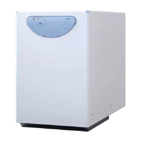
Sime SIME SUB HE/DHW 12/60 User manual

Sime Sub HE - DHW
ISO 9001 : 2000
CERTIFIED COMPANY
EN

3
CONTENTS
INSTALLER INSTRUCTIONS 3
MAIN INFORMATION 5
Manual purpose 5
Responsibility 5
Identification 5
Terms and definitions 6
How to apply for assistance 6
Symbols 6
TECHNICAL DATA 7
Supply 7
Main components and technical data 7
Functioning description 17
SAFETY INFORMATION 20
General warnings 20
Safe handlings 20
INSTALLATION INFORMATION 21
Unpacking 21
Characteristics of installation environment 21
Installing components 21
Disassembling the shell 22
System filling 23
Emptying system 24
FUNCTIONING ERRORS 25
MAINTENANCE 26
USER INSTRUCTIONS 27
INSTALLER INSTRUCTIONS

5
MAIN INFORMATION
Identification
Our products are manufactured in compliance with the requirements of the various ap-
plicable European Directives and are thus provided with the CE and all the necessary
documents.
The interest in the quality of our products leads us to their constant improvement. The-
refore we reserve the right to change at any time and without notice, the specifications
given in this document.
Our responsibility as a manufacturer can not be claimed in the following cases:
Failure to follow installation and use of the product.•
Lack or insufficient maintenance.•
Builder
responsibility
Installer
responsibility
The installer is responsible for the installation that must be in compliance with the ap-
plicable rules. Meet the following requirements:
Meet the requirement in this manual.•
Install the system in accordance with local laws and regulations.•
Alert the user of the obligation to control and periodic maintenance.•
Ensure that these instructions are left for the user.•
Responsibility
The manual is dedicated to the substation, and provides all the information needed for
assembly, installation and commissioning of the system.
Manual purpose
Positioning data plate on Substation.
Substation
A
N. Description
A Data plate
Fig. 1

6
Shows important information. Follow it carefully.
Shows a ban. Prohibited to the following behaviors.
Warning, generic danger and important notes.
Symbols
How to apply for assistance
For help and assistance contact service:
Sime Ltd service
Tel 08709 911114
Fax 08709 911115
Terms and definitions
Thermal group without burner. It Is Composed with heat exchangers provided by hot
water for CH and DHW..
The substation has no burner and is suitable for installation in houses connected to
district heating network.
Substation
Don’t touch, hot sufrace! Danger of burns!
Dont’t touch! Danger of shock!
Heating system at a distance of a neighborhood or city that uses the heat produced by
a thermal power plant, a cogeneration plant, or from a geothermal source. In a district
heating system, heat is distributed to buildings via a network of tubes in which flows the
hot water or steam.
[Taken from the Glossario dell’Autorità per l’Energia Elettrica ed il
Gas”].
District heating
District heating hydraulic circuit.
Network

7
TECHNICAL DATA
Supply
Main components and technical data
N. Description Q.ty
A Packaging 485x815x307 1
B Sime Substation 1
C Valves ¾”4
D Valves ½”2
ETemplate 1
FGuarantee 1
GUARANTEE
sime limited
AB
CE
D
F
The “Sime Sub HE/DHW” are a heating substations suitable for apartments and single-
family houses that are directly or indirectly connected to a heating network.
All internal wiring is factory fitted and the plumbing is well arranged. Thanks to its com-
pact size and low weight, the unit is convenient to fit into limited space. In new buildings,
it demands less space than traditional substations. It can also be connected to low tem-
perature heating systems.
The substation has two thermostatic mixing valves that supply the required temperatures
for central heating and domestic hot water. Domestic hot water is heated separately in a
high-capacity heat exchanger (see technical features).
The “Sime Sub HE/DHW” meets stringent demands for long-term performance. The heat
exchanger plates are manufactured in acid-resistant stainless steel. All components are
easily accessible for inspection and service.
Sime Substation
Fig. 1/a

8
Dimensions
33,5 65 65 65 65 65 93,5
82
750
91
125
50
C.W.I.
H.R H.M.R. H.M.S. H.W.O.
H.S
750
452 290
39
93,5 50 334 29,5
81
KEY
H.S. HEATING SUPPLY 22 mm COMPRESSION
H.R. HEATING RETURN 22 mm COMPRESSION
H.M.R. HEATING MEDIA RETURN (DISTRICT HEATING) 22 mm COMPRESSION
H.M.S. HEATING MEDIA SUPPLY (DISTRICT HEATING) 22 mm COMPRESSION
H.W.O. HEATING WATER OUTLET 15 mm COMPRESSION
C.W.I. COLD WATER INLET 15 mm COMPRESSION
LEGENDA
HS Heating supply 22 mm compression
HR Heating return 22 mm compression
HMR Heating media return (District heating) 22 mm compression
HMS Heating media supply (District heating) 22 mm compression
HWO Hot water outlet 15 mm compression
CWI Cold water inlet 15 mm compression
Front view Side view Rear view
Top view
Fig. 2

9
1
3
4
2
7
6
9
11
15
13
17
16
10
8
14
19
18
20
12
21
22
5
Main components
KEY
1 Control panel 12 Domestic hot water flow switch
2 Circulation pump 13 Filling loop
3 Motorized two way valve (CH primary circuit) 14 Differential pressure regulator capillary
4 Differential pressure regulator 15 Domestic hot water thermostatic mixing valve
5 Regulation valve 16 Motorized two way valve (DHW primary circuit)
6 Heating circuit filter 17 Expansion vessel
7 Heat counter (for code 8111003) 18 DHW plate exchanger
8 Temperature and pressure gauge 19 CH plate exchanger
9 Valves 3/4” 20 Drain valve
10 Valves 1/2” 21 3 bar heating system pressure relief valve
11 Heating Media supply filter (District heating) 22 Heat counter temperature sensor
Fig. 2/a
Front view Rear view

10
GENERAL SIME SUB HE/DHW
12/60
SIME SUB HE/DHW
12/60
Code number 8111003 8111004
Residual head with 700 l/h (CH) kPa 22,1 22,1
Supply voltage Volt 230 230
Supply frequency Hz 50 50
Net weight substation kg 32,3 32,3
Water filled weight substation kg 35,9 35,9
Minimum head input kPa 39,2 (at 1250 l/h)
26,5 (at 1000 l/h)
39,2 (at 1250 l/h)
26,5 (at 1000 l/h)
Working head kPa 14,7 (at 1250 l/h)
9,8 (at 1000 l/h)
14,7 (at 1250 l/h)
9,8 (at 1000 l/h)
Maximum pressure network bar 16 16
Maximum ∆P motorized two
way valve (CH and DHW primary
circuit)
bar 3,5 3,5
OPERATION DATA
Heating network
Maximum static operation pres-
sure bar 16 16
Maximum temperature °C 85 85
Volume l 1,3 1,3
Heating circuit
Max temperature °C 75 75
Maximum pressure bar 2,5 2,5
Relief valve opening pressure bar 3 3
Volume l 1,1 1,1
Expansion vessel volume l 8 8
Hot water circuit
Maximum/minimum pressure bar 7 / 0,5 7 / 0,5
Temperature range °C 30 ÷ 60 30 ÷ 60
Volume l 0,95 0,95
CONNECTIONS
Heating media supply (District heating) 3/4” 3/4”
Heating media return (District heating) 3/4” 3/4”
Heating supply 3/4” 3/4”
Heating return 3/4” 3/4”
Cold water 1/2” 1/2”
Hot water 1/2” 1/2”
Technical
features

11
Examples of
applications
Condition:
Steady state operation
Max Power absorbed
CH=12 kW
SIMESUB 12/60
NETWORK Flow = 750 l/h
(loss=17 kPa)
THMS = 85 °C
Flow = 750 l/h
(loss=17 kPa)
THMS = 80 °C
Flow = 750 l/h
(loss=17 kPa)
THMS = 70 °C
Flow = 1000 l/h
(loss=30 kPa)
THMS = 85 °C
Flow = 1000 l/h
(loss=30 kPa)
THMS = 80 °C
Flow = 1000 l/h
(loss=30 kPa)
THMS = 70 °C
Flow = 1150 l/h
(loss=40 kPa)
THMS = 85 °C
Flow = 1150 l/h
(loss=40 kPa)
THMS = 80 °C
Flow = 1150 l/h
(loss=40 kPa)
THMS = 70 °C
DHW
FUNCTION
Flow= 20 l/min
THWI=10°C
THMR= 29 °C THMR= 28 °C THMR= 22,5 °C THMR= 31 °C THMR = 30 °C THMR = 28 °C THMR= 38 °C THMR= 33 °C THM = 31 °C
THWO= 45 °C THWO= 42,5 °C THWO= 40 °C THWO= 55 °C THWO= 51,5 °C THWO= 45 °C THWO= 55 °C THWO= 55 °C THWO= 47 °C

12
The differential pressure regulator keeps the difference in pressure found in two points of
a hydronic circuit at a constant level, corresponding to the set value. The device is inserted
in the circuit return pipe and is connected, by way of a capillary pipe, to the flow pipe. It is
used in variable flow rate systems, with motorised valves, to limit the increases in differen-
tial pressure that are created when these valves are closed, either totally or partially. The
action of the device is proportionate to the variation in differential pressure that is created,
to restore the ∆p conditions set.
OPERATION DATA
Maximum pressure bar 16
Maximum differential pressure bar 2
Minimum temperature (water) °C 2
Minimum temperature (water with antifreeze) °C -20
Maximum temperature °C 100
Regulation field kPa 5 - 30
The differential pressure regulator is calibrated and sealed at factory: the value for Sim-
esub HE/DHW 12/40 and Simesub HE/DHW 12/60 is 4; can be adjusted to the desired value
by only qualified SIME technicians with graph in fig. 3.
Presetting 1,0-7,5
Flow rate [l/h]
Dp [mbar]
Fig. 3
The Energy meter is the device that stores the amount of heat used by the temperature
difference between HMS and HMR and the amount of water used route under its control.
The installation of the heat counters must comply with the normative reference EN•
1434, parts 1 + 6 , and I.E.E wiring regulations.
This heat counter is manufactured according to the current safety regulations. The•
maintenance operations must be made by authorized personnel only.
Breakage of any of the seals on the heat counter will invalidate the warranty.•
A minimum separation of 20 mm must be maintained from any electromagnetic de-•
vice, and a minimum of 50mm from any other electrical wiring.
The cables to the temperature sensors must not be tightly coiled, lengthened or•
shortened.
Clean using a dry cloth.•
When multiple heat counters are installed it is important to observe the wiring polar-•
ity.
The differential pressure regulator
Energy meter (for code 8111003)

13
TECHNICAL DATA
Nominal capacity m3/h 2,5
Maximum capacity m3/h 5,0
Temperatures range °C 15,,,90
Calculating device
Temperature range °C 1,,,130
Temperature difference K 3,,,100
Power supply Lithium 3 V Battery
Functioning duration Years 6 + 1
Data storing self-contained
Display 8 digit
Interfaces Infrared / M-bus
Temperature Sensors
Type Platinum
Connection 2-wire technique
Diameter mm 5,0
Cable length m 1.5
When the device shows an error, this is the symbol that is actually displayed. There are
seven likely causes that lead to the error and sometimes, they may be displayed at the
same time.
The error is displayed by means of a code format “ERR xx”. Where “xx” is for the error
number and is showed in hesadecimal form (fig. 4).
Errors code
Fig. 4
Error codes
Error codes
(hexadecimal)
Sum error
Faulty
E2 PROM
Error codes
(hexadecimal)
Faulty reel
Reset
Measure of
reference error
Faulty return
temp. sensor
Faulty flow
temp. sensor
Error description
Error Description Effect Possible cause
Faulty Inp. Fl. Sensor The flow temperature sensor is
faulty
No calculation performed. The records for
flow and energy are not updated (no new
memorised data)
Cut sensor cable; removed sensor
cable
Faulty Ret. Fl. Sensor The flow return temperature sen-
sor is faulty
No calculation performed. The records for
flow and energy are not updated (no new
memorised data)
Cut sensor cable; removed sensor
cable
Faulty Ref. sensor Error during the measure of refe-
rence
No calculation performed. The records for
flow and energy are not updated (no new
memorised data)
The main circuit of the electronic
unit is faulty
Faulty reel Scanning is not functioning cor-
rectly
No calculation performed. The records for
flow and energy are not updated (no new
memorised data)
Removed reel; the connecting cable
between the calculating device seat
and the flow sensor is damaged
Reset The electronics of the calculating
device have been restored
The measurements have been lost since the
last data collection in the E2PROM, (at the
most the measurements for 1 day)
EMC
Faulty E2PROM No communication with E2PROM After re-setting, the instrument is not functio-
ning Faulty components
Sum error The instrument configuration in
the E2PROM is incorrect
No calculation is carried out. The flow and
energy records are not updated Faulty component
When an error occurs, the instrument must be replaced and sent to the supplier for testing

14
The heat counter is equipped with a liquid crystal display, 8 figures and special letters.
There are three information “levels” as follows:
a) Main level•
b) Technical level•
c) Static level•
The information is recalled by pressed the button. A short press of the button will step
through the information at each level. Holding the button presseed will move through the
levels.
After 1 minute of non-use, the display returns back to the standard display.
Display
Level
Level
1) Energy used in MWh – standard
display
2) Test of the display. Make sure
all the display sections are displayed
simoultaneously.
3) Value reading at a fixed date.* The
value is displayed by turn with the
actual date
Level
Level
3) Value reading at a fixed date.*
The value alternates with the actual
date
4) Total voilume (in m3) from the
installation
5) Instantaneous power in KW
6) Instantaneous flow rate in m3/h
7) Date
8) Error code
1) Maximum power in kW
2) Maximum capacity in m3/h
3) Input temperature in °C
4) Output temperatures in °C
5) Temperatures difference
6) Days of functioning from calibra-
tion
7) Impulses values per litre
8) M-bus address
9) Serial number
10) Firmware/software version
1) Last reading alternated with the
respective date
2 – 16) Consumption reading in the previous 15
months alternated with the respective date*
* Up to the end of the month, the consumption data and the date are displayed at zero Fig. 5

15
Infrared (IrdA Port)
For data transfer from microCLIMA to the computer, it is necessary to wire an optical head
onto the serial gate of the computer. The optical head and the necessary software are
available upon request as optional. The IrdA port is activated with an appropriate key. After
60 seconds of inactivity, the gate will shut-off automatically.
M-bus
M-Bus interface is available upon demand (optional). When using this system, checking of
the main data and the measurements cannot be altered. The protocol is in compliance with
Standard EN1434-3 and with Standards IEC 870.
Baud: standard: 2400 Bd. It is important to outline the typology M-Bus (length of the wiring
cables, cross sections of the cable) has to correspond to the baud unit of the heat counter.
During the M-Bus communication, it is not possible to use the other communication in-
terfaces of the device (key or IrdA), and vice versa. Note: the heat counters are battery fed,
and that’s the reason why the simultaneous communications are so limited. In a M.-Bus
net of 250 heat counters, for every tester no. 24 demands per day are possible. If a small
number of demands and/or a small number of heat counters are wired to the bus, the un-
used quantity of available demands is stored onto the device.
The life battery of the battery depends on the quantity of data exchanged. Its minimum life
is 6 years.
Output signals
The device is equipped with a signal outlet fed by electronic inputs, to be required when
the PO is submitted.
The contact is type: class A0, according to Normative EN1434, and produces the counting
impulses of the heat counter. The outlet of the impulses closes in relation to the measured
volume of the appliance (see data plate) for a duration of 125 ms. When the impulses
through the outlet are many, the gap time between the impulses is of 125ms. Should the
nominal data and the edge of the contact be taken into consideration, the end user is free
to set-up the data about the impulses in a wide range of options. The contact (fig. 6) can be
wired by means of a large number of devices, aimed to get the outlet data.
The minimum duration of the battery for the heat counters, equipped with outlet impulses,
is of 6 years plus 1.
Impulses:
– Heat: standard: 1kWh/impulse, or optionals
– Volume: standard: 100 l/impulse
Communication
Technical data
Max. switching current 300 mA (AC/DC)
Max. switching voltage 35 V (AC/DC)
Max. switching power supply 300 mW
Insulating resistance >109Ohm
Resistance of contact max. 25 Ohm
Capacity of contact max. 1.5 pF
Maximum current 120 mA
Dielectric resistance (open contact) 350 V (AC/DC)
Connect here the device for acquiring the output data
Fig. 6

16
Circulation pump
Head avaiable
To system
Residual head for the heating system is shown as a function of rate of flow in the graphs in
fig. 7 with CH thermostatic mixing valve setted to 60°C.
Set the pump speed of the heating circulation pump according to the system head (Fig.
7).
Use the lowest setting that manages the heating demand for best efficiency.
Fig. 7
0
100
200
300
400
500
600
0
Flow rate (l/h)
Head (mbar)
100 200 300 400 500 600 700 800 900
Central Heating Residual Head
l/h Speed 1 Speed 2 Speed 3
0 400 545 600
400 212 432 517
700 258 378
800 314
-
--
Speed 1
Speed 2
Speed 3
The energy meter is used for measurement of both heat and cooling in all water based
plants. The meter is simple to read and verify. The energy meter receives volume pulses
from the connected flow meters and calculates the energy for every predetermined water
volume. The energy calculation includes temperature measurements in flow and return as
well as correction for density and heat content according to EN 1434.
The energy meter is calibrated at factory and it is available on request.
Kit Energy meter code 8109811 (for code 8111004)

17
2
3
5
6
7
1
11
15
16
19 18
CWI
HWO
HMSHMR
HRHS
12
10
9
8
20
21
17
000 13
14
22
4
Functional
diagram
LEGENDA
1 Filling loop 16 Motorized two way valve (DHW primary circuit)
2 Circulation pump 17 Expansion vessel
3 Motorized two way valve (CH primary circuit) 18 DHW plate exchanger
4 Regulation valve 19 CH plate exchanger
5Differential pressure regulator 20 Drain valve
6 Heating circuit filter 21 3 bar heating system pressure relief valve
7 Heat counter (for code 8111003) 22 Room thermostat
8 Temperature and pressure gauge
9 Valves 3/4” CONNECTIONS
10 Valves 1/2” HS Heating supply
11 Heating Media supply filter (District heating) HR Heating return
12 Domestic hot water flow switch HMR Heating media return (district heating)
13 Heat counter temperature sensor HMS Heating media supply (district heating)
14 Differential pressure regulator capillary HWO Hot water outlet
15 Domestic hot water thermostatic mixing valve CWI Cold water inlet
Fig. 9
Functioning description

18
Electrical
wiring
“Sime Sub HE/DHW” is supplied with an electric cable. Should this require replacement,
it must be purchased exclusively from SIME. The electric power supply to the substation
must be 230V - 50Hz single-phase through a fused main switch, fitted with a 3 A fuse, with
at least 3 mm spacing between contacts. Respect the L and N polarities and the earth
connection.
This must be carried out by a qualified electrician.The wiring conforms to the applicable rules
for CE marking and has undergone electrical safety testing and function testing
(fig. 10).
SIME declines all responsibility for injury or damage to persons, animals or property,
resulting from the failure to provide for proper earthing of the appliance.
Before any work is done on the substation, it must be isolated from the power supply by
turning off at the external switched supply.
LCH LDHW
FA
MSW
VCH
PVDHW
L
N
1
23456789
10
11
12 13 14
1
423 5
BLUE
GREY
BROWN
BLACK
BROWN
BLUE
BLACK
BLACK
BROWN
BLUE
WHITE
RED
W
S
RT
LN
MS
OP
456
7
FL
WSS
Fig. 10
LEGENDA
MSW ON-OFF SWITCH
WSS WINTER/SUMMER SWITCH
MS MAIN SUPPLY
FA FUSE 1,6 AT
VCH CH MOTORIZED VALVE
VDHW DHW MOTORIZED VALVE
P CH PUMP
FL DHW FLOW SWITCH
LDHW DHW LIGHT
LCH CH LIGHT
OP SWITCH CONNECTIONS FOR OPTIONAL CLOCK
RT ROOM THERMOSTAT CONNECTION
Note: Remove 6-7 connections for OP

19
The boiler heats the water, which is distributed to multiple buildings through the distri-
bution network. When it is in substation heating exchanger, water to water transfer net-
work in the distribution system inside the building the necessary heat for space heating
and domestic hot water production. At the end of this process, the water, now cooled,
returns to Central to be reheated.
Functioning
H.S.
H.R.
H.M.R.
H.M.S.
H.W.O.
C.W.I.
Fig. 11

20
General warnings
The electrical equipment at end of life should be treated as waste electrical and•
electronic equipment (WEEE)
Dispose of the substation at the end of life correctly according to directives and•
local and national regulations.
Do not touch the substation when it is ON.•
Do not touch the substation with wet hands.•
Do not touch the substation with barefoot.•
Do not remove or bypass safety devices or destroy the whole system.•
Do not use water jets direct or indirect substation.•
Do not open the door of the substation when it is powered.•
The manufacturer is not liable for damage caused to the entire substation for pur-•
poses other than those described in this manual.
The manufacturer is not liable for failure or forced rimorzione symbols and requi-•
rements present in the system components.
Obey all local laws regarding safety and risk prevention.•
Safe handlings
The manufacturer is not liable for damage caused to the entire substation for pur-•
poses other than those described in this manual
The temperature and pressure of the water district heating system are very high.•
Only qualified technicians are authorized to perform the installation, initial start-
up and maintenance of substation
The manufacturer is not liable for the failure or forced rimorzione symbols and•
requirements present in the system components
Obey all local laws regarding safety and risk prevention•
This Substation may require 2 or more operatives to move it into its installation site,•
remove it from its packaging and during movement into its installation location. Ma-
noeuvring the boiler may include the use of a sack truck and involve lifting pushing
and pulling.
Remove the package at the installation site•
Caution should be exercised during these operations•
During all manoeuvres and handling actions, every attempt should be made to ensure the
following unless unavoidable and/or the weight is light. Operatives should be knowledge-
able in handling techniques when performing these tasks and the following precautions
should be considered:
Grip the boiler at the base•
Be physically capable•
Use personal protective equipment as appropriate e.g. gloves, safety footwear•
Avoid direct contact with sharp edges•
Avoid contact with any hot surfaces•
Keep back straight•
Avoid twisting at the waist•
Always grip with the palm of the hand•
Keep load as close to the body as possible•
Always use assistance•
Please be aware that due to the wet testing of the appliance, there may some r sidual•
water in the hydraulic circuit.
Protect any surfaces, carpets or floorings.•
Use a suitable container to catch any water that escape when removing the protective•
caps from the connections.
SAFETY INFORMATION

21
Unpacking
Please see the handling notice, enclosed in this manual• .
Unpack the substation, ensure that the contents are as specified. If the substation is•
damaged, do not install it and contact the supplier.
When lifting or maneuvering the substation do not do so by holding the internal com-•
ponents.
Make sure the mounting location is adequate to support the weight of the substation•
and complies with any applicable legislation. The system can generate noise during
operation and this should be considered where substation is installed.
Installation and commissioning must be performed only by qualified service per-•
sonnel.
Due to vibrations during transportation and thermal expansion, nuts and gaskets•
must be tightened upon installation.
Characteristics of installation environment
The premises must be suitable for installation of:
HUMIDITY less than 90%
TEMPERATURE RANGE: 0 ÷ 60 °C
Wall can withstand the weight of the substation.
Isolated from any electromagnetic interference.
PREPARATION for electrical and hydraulic connections.
INSTALLATION INFORMATION
Refer to the applicable regulations of the district heating supplier.•
Read the technical data.•
Installing components
Valves ¾”
Valves ½”
Follow the steps listed below:
Flush out the heating and hot water systems.1.
Fit the isolation valves using the washers provided2. .
Connect to the hydraulic system, ensuring correct orientation3. .
Fig. 12

22
Disassembling the shell
4 x
1
2
3
Switch off the voltage.
Wear the safety glasses.
Wear the safety gloves.
The casing may be removed completely to facilitate substation maintenance, as shown in
fig. 12/a. Proceed as follows:
Remove the 4 screw1. s.
Lift up the shell2. .
Pull forward and remove the shel3. .
To access the internal components of the substation, the control panel can be tilted for-
wards after removal of the fixing screw.
Fig. 12/a
Table of contents
Other Sime Heating System manuals
Popular Heating System manuals by other brands

Vent-Axia
Vent-Axia Sentinel Kinetic Operation manual

VWR
VWR VisiScope 300 Series instruction manual

PrecisionTemp
PrecisionTemp TWINTEMP JR. Operation description
JOSAM
JOSAM JO960 A Operator instruction and safety regulations
Paul
Paul NOVUS 300 Service instructions
STIEBEL ELTRON
STIEBEL ELTRON TWS 10 Operating and installation

Vortice
Vortice VORT-NRG Series Instruction booklet
RenewAire
RenewAire HE ERV Series Installation, operation and maintenance manual

Fuba
Fuba AHZ780 manual
Fujitsu
Fujitsu Heat pump Operation manual
RenewAire
RenewAire EV Series Installation, operation and maintenance manual
Alnor
Alnor HRU-SlimAIR-250 user manual
