Simex SWZ-W610 User manual

SIMEX®
USER MANUAL for
digital clock
type: SWZ-W6 0
firmware version: 1.01 or higher
Read the user's manual carefully before starting to use the unit.
Producer reserves the right to implement changes without prior notice.
22.10.2007 .2.00

User manual for digital clock SWZ-W610
CONTENTS
1. BASIC REQUIREMENTS AND USER SAFETY........................................................................................3
2. GENERAL CHARACTERISTICS................................................................................................................4
3. TECHNICAL DATA......................................................................................................................................4
4. DEVICE INSTALLATION............................................................................................................................6
4.1. UNPACKING.......................................................................................................................................6
4.2. ASSEMBLY........................................................................................................................................6
4.3. CONNECTION METHOD...................................................................................................................7
4.4. MAINTENANCE................................................................................................................................10
5. FRONT PANEL DESCRIPTION................................................................................................................10
6. PRINCIPLE OF OPERATION...................................................................................................................11
6.1. DISPLAYING MODE........................................................................................................................11
6.2. THERMOMETER FUNCTION..........................................................................................................12
6.2.1. Tem erature sensor module installation.................................................................................12
6.3. SYNCHRONIZATION OF THE CLOCK WITH DCF77 SIGNAL.................................................... 12
6.3.1. Installation of DCF77 module.................................................................................................12
7. DEVICE PROGRAMMING.........................................................................................................................14
7.1. PROGRAMMING MENU..................................................................................................................14
7.2. PARAMETERS EDITION.................................................................................................................14
7.2.1. Numeric arameters (digit change mode)...............................................................................14
7.2.2. Numeric arameters (slide change mode)..............................................................................15
7.2.3. Switch arameters (“LIST” ty e).............................................................................................15
7.3. MENU DESCRIPTION.....................................................................................................................16
7.3.1. ”bri” arameter.........................................................................................................................16
7.3.2. “dLy” menu..............................................................................................................................16
7.3.3. “rtc” menu................................................................................................................................16
7.3.4. “Func” menu............................................................................................................................17
7.3.5. “dCF” menu.............................................................................................................................17
7.3.6. ”rS” menu.................................................................................................................................18
7.3.7. ”Scod” arameter....................................................................................................................19
7.3.8. ”Edit” arameter......................................................................................................................19
7.3.9. ”dEFS” arameter....................................................................................................................19
7.3.10. ”SErv” menu..........................................................................................................................19
7.4. MENU STRUCTURE........................................................................................................................20
. THE MODBUS PROTOCOL HANDLING.................................................................................................21
8.1. LIST OF REGISTERS......................................................................................................................21
8.2. TRANSMISSION ERRORS DESCRIPTION....................................................................................23
8.3. EXAMPLES OF QUERY/ANSWER FRAMES.................................................................................23
9. DEFAULT AND USER'S SETTINGS LIST...............................................................................................25
2

User manual for digital clock SWZ-W610
Explanation of symbols used in the manual:
- This symbol denotes es ecially im ortant guidelines concerning the installation and
o eration of the device. Not com lying with the guidelines denoted by this symbol
may cause an accident, damage or equi ment destruction.
IF THE DEVICE IS NOT USED ACCORDING TO THE MANUAL THE USER IS
RESPONSIBLE FOR POSSIBLE DAMAGES.
- This symbol denotes es ecially im ortant characteristics of the unit.
Read any information regarding this symbol carefully
1. BASIC REQUIREMENTS AND USER SAFETY
- The manufacturer is not responsible for any damages caused by
inappropriate installation, not maintaining the proper technical condition
and using the unit against its destination.
- Installation should be conducted by qualified personnel . During installation all
available safety requirements should be considered. The fitter is responsible for
executing the installation according to this manual, local safety and EMC
regulations.
- The unit must be properly set-up, according to the application. Incorrect
configuration can cause defective operation, which can lead to unit damage or
an accident.
- If in the case of a defect of unit operation there is a risk of a serious threat
to the safety of people or property additional, independent systems and
solutions to prevent such a threat must be used.
- The unit uses dangerous voltage that can cause a lethal accident. The unit
must be switched off and disconnected from the power supply prior to
starting installation of troubleshooting (in the case of malfunction).
- Neighbouring and mating equipment must meet the requirements of appropriate
standards and regulations concerning safety and be equipped with adequate
anti-overvoltage and anti-interference filters.
- Do not attempt to disassemble, repair or modify the unit yourself. The unit
has no user serviceable parts. Units, in which a defect was stated must be
disconnected and submitted for repairs at an authorized service centre.
- In order to minimize fire or electric shock hazard, the unit must be protected
against atmospheric precipitation and excessive humidity.
- Do not use the unit in areas threatened with excessive shocks, vibrations, dust,
humidity, corrosive gasses and oils.
3
i
!
!
!

User manual for digital clock SWZ-W610
- Do not use the unit in explosion hazard areas.
- Do not use the unit in areas with significant temperature variations, exposed to
condensation or icing.
- Do not use the unit in areas exposed to direct sunlight.
- Make sure that the ambient temperature (e.g. inside the control box) does not
exceed the recommended values. In such cases forced cooling of the unit must
be considered (e.g. by using a ventilator).
The unit is designed for operation in an industrial environment and must
not be used in a household environment or similar.
2. GENERAL CHARACTERISTICS
The SWZ-W6 0 digital clock indicates present time, date and temperature (option) on
6-digit super-bright LED display. The reading are showed in sequence: present time (hours,
minutes and seconds), present date (day of month, month and two last digits of year) and
temperature (while the device is equipped with optional temperature sensor). The time is
presented in 24-hours mode only, and internal battery preserves proper time counting, even if
device is turned off from power supply. The SWZ-W6 0 is designed to operate in closed
rooms where relative humidity is lower than 90% and no condensation occurs. The brightness
of display can be adjusted in 8 steps. It is possible to connect external DCF-77 signal receiver
to the clock. (DCF-77 signal receiver is not a part of the SWZ-W6 0 set. It is an additional
equipment.)
The device has 4 buttons used for main pre-sets programming. To get higher protection
level, the keyboard is mounted under transparent cover. It is possible to set the device using
Infra Red controller, or RS 485 serial interface with MODBUS RTU protocol.
The remote controller keyboard is equivalent to the device keyboard (Remote controller is
not a part of the SWZ-W6 0 set. It is an additional equipment.).
3. TECHNICAL DATA
Power supply voltage
(depending on version)
External fuse (required)
Power consumption
85...230...260 AC/DC; 50 ÷ 60 Hz
19...24...50 DC; 16...24...35 AC
T - type, max. 2 A
max. 11 A @ 85 ÷ 260 AC/DC
max. 11 A @ 16 ÷ 35 AC
max. 10 W @ 19 ÷ 50 DC
Outputs
supply 24 :
supply 5 :
24 DC ± 5% / max. 100 mA;
5 DC ± 5% / max. 50 mA;
4
!
!

User manual for digital clock SWZ-W610
Inputs
temperature sensor:
DCF77 receiver:
designed to digital temperature sensor, 2-wire
connection
the receiver output NPN or push-pull type, signal with
positive or negative polarization
Displaying range
time:
date:
temperature (option):
24h format : hours, minutes seconds
day of month, month, 2 last digits of year
-40°C to 85°C, resolution: 1°C
Internal clock battery non-removable, 3 , Li
Communication interface RS 485, 8N1 and 8N2, Modbus RTU, not separated
Baud rate 1200 bit/s ÷ 115200 bit/s
Display LED, 4 digit 100mm height + 2 digit 57mm height, red,
with 8-steps brightness regulation
Data memory non-volatile memory, EEPROM type
Protection level IP 30
Housing type
Housing material
Housing dimensions
Wall mounted
aluminium + methyl polimethacrylate
578 x 208 x 102 mm
Operating temperature
Storage temperature
0°C to +50°C
-10°C to +70°C
Humidity
Altitude
5 to 90% no condensation
up to 2000 meters above sea level
Screws tightening max. torque 0.5 Nm
Max. connection leads diameter 2.5 mm2
Safety requirements according to: PN-EN 61010-1
installation category: II
pollution degree: 2
voltage in relation to ground: 300 AC
insulation resistance: >20MΩ
insulation strength between power supply and
input/output terminal: 1min. @ 2300
EMC according to: PN-EN 61326
This is a class A unit. In housing or a similar area it can cause radio
frequency interference. In such cases the user can be requested to use
appropriate preventive measures.
5
!

User manual for digital clock SWZ-W610
4. DEVICE INSTALLATION
The unit has been designed and manufactured in a way assuring a high level of user
safety and resistance to interference occurring in a typical industrial environment. In order to
take full advantage of these characteristics installation of the unit must be conducted correctly
and according to the local regulations.
- Read the basic safety requirements on page 3 prior to starting the installation.
- Ensure that the power supply network voltage corresponds to the nominal
voltage stated on the unit’s identification label.
- The load must correspond to the requirements listed in the technical data.
- All installation works must be conducted with a disconnected power supply.
- Protecting the power supply clamps against unauthorized persons must be
taken into consideration.
4.1. UNPACKING
After removing the unit from the protective packaging, check for transportation damage. Any
transportation damage must be immediately reported to the carrier. Also, write down the unit
serial number on the housing and report the damage to the manufacturer.
Attached with the unit please find:
- user’s manual,
- warranty,
4.2. ASSEMBLY
- Disconnect the power supply prior to starting assembly.
- During installation all available safety requirements should be considered.
- The mounting method must to preserve high breaking strength, at least 4 times
the mass of the device.
- Check the correctness of the performed connections prior to switching the unit on.
To install the device two holes must be prepared (distance like in Figure 4.1) with
screws or hooks. The device should be installed using its handles placed on the top
of housing.
6
!
!
!

User manual for digital clock SWZ-W610
Figure 4.1. Device and assembly dimensions
4.3. CONNECTION METHOD
Caution
- Installation should be conducted by qualified personnel . During installation all
available safety requirements should be considered. The fitter is responsible for
executing the installation according to this manual, local safety and EMC
regulations.
- The unit is not equipped with an internal fuse or power supply circuit breaker.
Because of this an external time-delay cut-out fuse with minimal possible nominal
current value must be used (recommended bipolar, max. 2A) and a power supply
circuit-breaker located near the unit. In the case of using a monopolar fuse it must
be mounted on the phase cable (L).
- The power supply network cable diameter must be selected in such a way that in
the case of a short circuit of the cable from the side of the unit the cable shall be
protected against destruction with an electrical installation fuse.
- Wiring must meet appropriate standards and local regulations and laws.
- In order to secure against accidental short circuit the connection cables must be
terminated with appropriate insulated cable tips.
- Tighten the clamping screws. The recommended tightening torque is 0.5 Nm.
Loose screws can cause fire or defective operation. Over tightening can lead to
damaging the connections inside the units and breaking the thread.
- In the case of the unit being fitted with separable clamps they should be inserted
into appropriate connectors in the unit, even if they are not used for any
connections.
7
!
578 mm
554 mm
102 mm
208 mm

User manual for digital clock SWZ-W610
- Unused clamps (marked as n.c.) must not be used for connecting any
connecting cables (e.g. as bridges), because this can cause damage to the
equipment or electric shock.
- If the unit is equipped with housing, covers and sealing packing, protecting
against water intrusion, pay special attention to their correct tightening or clamping.
In the case of any doubt consider using additional preventive measures (covers,
roofing, seals, etc.). Carelessly executed assembly can increase the risk of electric
shock.
- After the installation is completed do not touch the unit’s connections when it is
switched on, because it carries the risk of electrical shock.
Due to possible significant interference in industrial installations appropriate measures
assuring correct operation of the unit must be applied. To avoid the unit of improper
indications keep recommendations listed below.
–Avoid common (parallel) leading of signal cables and transmission cables together with
power supply cables and cables controlling induction loads (e.g. contactors). Such cables
should cross at a right angle.
–Contactor coils and induction loads should be equipped with anti-interference protection
systems, e.g. RC-type.
–Use of screened signal cables is recommended. Signal cable screens should be
connected to the earthing only at one of the ends of the screened cable.
–In the case of magnetically induced interference the use of twisted couples of signal
cables (so-called “spirals”) is recommended. The spiral (best if shielded) must be used
with RS-485 serial transmission connections.
–In the case of interference from the power supply side the use of appropriate anti-
interference filters is recommended. Bear in mind that the connection between the filter
and the unit should be as short as possible and the metal housing of the filter must be
connected to the earthing with largest possible surface. The cables connected to the filter
output must not run in parallel with cables with interference (e.g. circuits controlling relays
or contactors).
Connections of power supply voltage and control signals are executed using the screw
connections on the back of the unit’s housing.
Figure 4.2. Method of cable insulation re lacing and cable terminals
8
!
max. 2 mm
6-7 mm

User manual for digital clock SWZ-W610
Figure 4.3. Terminals descri tion
- All connections must be made while power supply is disconnected
- The device housing should be grounded. Protective Earth (PE) cord should be
mounted using eye terminal, connectinh it with proper screw placed near of
power terminals.
Recommended installation torque of Protective Earth terminal is 2 Nm.
- Power supply connection must be made using 3-wire cord.
- After installation, power cord gland should be tighten up, to prevent cable
move.
Metal housing must be connected with PE (grounded), using terminal marked
with symbol:
Be careful while nuts tightening.
De ending on version:
85...230...260V AC/DC or
19...24...50V DC; 16...24...35V AC
Figure 4.4. Connection of ower su ly
2 5 6 7 8 9
GND
DATA+
DATA-
RS - 485
3 4
+24V ±5%
Imax = 100mA
0
- Uo +
2 3 4 5 6
GND GND
+5V ±5%
Imax = 50mA
THERM DCF
Power
supply
(depending on version)
FUSE
2
L N
N
L
!
!

User manual for digital clock SWZ-W610
Figure 4.5. Connection of tem erature sensor module and DCF77 signal receiver (o tional)
4.4. MAINTENANCE
The unit does not have any internal replaceable or adjustable components available to
the user. Pay attention to the ambient temperature in the room where the unit is operating.
Excessively high temperatures cause faster ageing of the internal components and shorten the
fault-free time of unit operation.
In cases where the unit gets dirty do not clean with solvents. For cleaning use soft, dry cloth.
In the case of more significant contamination use warm water with small amount of detergent
to wet the cloth.
Using any other agents can cause permanent damage to the housing.
Product marked with this symbol should not be placed in municipal waste. Please
check local regulations for disposal and electronic products.
5. FRONT PANEL DESCRIPTION
Caution: Due to necessity of housing opening while use of internal
keyboard - it should be done very carefully by a fitter.
If changes of parameters must be done often, it is recommended to use
optional IR controller.
10
!
2 3 4 5 6
GND
temperature
sensor
module
data line
GND
digital output
+5V
DCF77
signal
receiver
infra-red receiver
rogramming
ushbuttons
dis lay
MENU
ESC ENTER
!

User manual for digital clock SWZ-W610
Symbols and functions of push-buttons:
Symbol used in the manual: [ESC/MENU]
Functions:
• Enter to main menu ( press and hold by at least 2 sec.)
• Exit the current level and Enter to previous menu (or displaying mode)
• Cancel the changes made in parameter being edited
Symbol used in the manual: [ENTER]
Functions :
• Start to edit the parameter
• Enter to the sub-menu,
• Confirmation of changes made in parameter being edited
• Changing of display mode, in sequence: present time, present date and
temperature (optional)
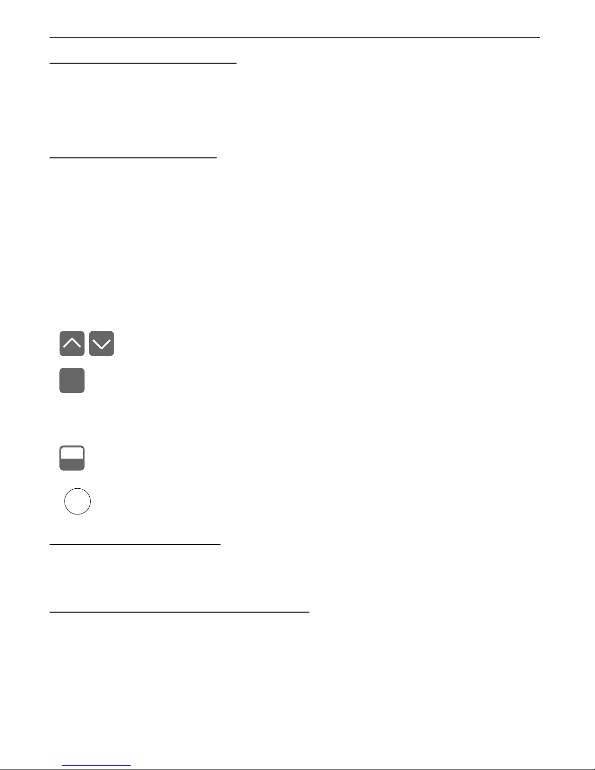
Symbol used in the manual: [^] [v]
Functions :
• Change of the present menu,
• Modification of the parameter value,
• Change of the display mode.
6. PRINCIPLE OF OPERATION
After turning the power supply on, device ID and software version are showed on the
display, next the digital indicator goes to the display mode.
6.1. DISPLAYING MODE
In normal mode current time is presented in format „hours:minutes seconds” or current
date in format „day.month.year”. Additionally, if digital temperature sensor module is
connected to {THERM} input, the device can display current temperature near the sensor. The
display can show only one of these parameters, or can change them in sequence, with periods
selected by user.
The displaying time of particular readings are defined by parameters ”dL c” (time displaying
period), ”dL d” (date displaying period) and ”dL t” (temperature displaying period).
• To omit the date in displaying sequence, parameter ”dAtE” of ”Func” menu
must be switched to ”oFF”. If ”dAtE” = ”oFF”, then parameter ”dL d” is
unavailable.
• To add displaying of temperature in sequence, thermometer function must be
on (parameter ”thEr” of ”Func” menu set to ”on”). If this function is off (”thEr”
= ”oFF”) parameter ”dL t” is unavailable.
Pressing ”ENTER” button, user can switch display to show selected reading. Successive
pressing of this button causes in displaying of next reading in the cycle.
Setting any of ”dL c”, ”dL d” or ”dL t” display period to „00” (zero) causes in stopping of
the sequence corresponding reading. If user press ”ENTER” button after stopping the
sequence, and display period of current reading is different than 0, the sequence run until next
reading with display period equal „00”.
11
MENU
ESC
ENTER
i

User manual for digital clock SWZ-W610
If displaying periods of all readings are set to zero, then successive pressing of “ENTER”
button switches readings, and they are displayed permanently.
All accessible parameters can be changed by entering the menu (see: DEVICE
PROGRAMMING). Use the local keyboard or the remote controller to do it. (Note: all
parameters can be remote changed via RS-485 interface).
Configuration of the device (via menu or RS 485 interface) do not stops device.
6.2. THERMOMETER FUNCTION
The SWZ-W6 0 is equipped with {THERM} input. It allows to connect digital thermometer
module (optional) to the device. To enable displaying of temperature in the sequence, the
thermometer function must be on (parameter ”thEr” of ”Func” menu set to ”on”). Parameter
”dL t” (available only while thermometer function is on) defines display time of temperature.
6.2.1. Temperature sensor module installation
Avoid of mounting the module near of the doors, windows (specially near of rooms with
different temperature), in places of high air flow, sunny places and near of artificial light
sources (like bulbs) etc.
Due to possibility of electromagnetic noise while using long connection wires,
a temperature sensor should be equipped with denoising filter.
Figure 6.1. Connection of tem erature sensor module to SWZ-W610
6.3. SYNCHRONIZATION OF THE CLOCK WITH DCF77 SIGNAL
The DCF77 is a radio signal contained informations about current time (central Europe).
Sending time is official UE time. Amplitude modulated signal is sent in LW band on 77.5 kHz
frequency. The transmitter is placed in Mainflingen, near of Frankfurt (Germany), and has
about 2500km of coverage (power about 50 kW). There are coded informations about current
hour, minute, date, day of week in the signal, and they are synchronized to high-precision
atomic time standard. One data pocket is transmitted over 59 seconds.
6.3.1. Installation of DCF77 module
To obtain proper reception of DCF77 signal, correct location and orientation of receiver
aerial is essential. Due to DCF77 receivers are usually sensitive to electromagnetic noise (also
generated by computers, monitors, T sets, motors and other devices), it is recommended to
12
2 3
GND
temperature
sensor
module
data line
i
i

User manual for digital clock SWZ-W610
place them far off of the noise sources. Periodical disturbances in reception can be caused by
storms. Unfortunately in unfavourable conditions, proper reception of full information can be
possible only at night, while all sources of disturbances are off.
Figure 6.2. Connection of DCF77 module to SWZ-W610
It is recommended to set „on” parameter „diSP” of „dCF” submenu. It allows to observe
DCF module output state (after connection to {DCF} input). If resting state of the module
output had been set correctly (see parameter „modE” of „dCF” submenu), then digital point of
most right digit flashes in time with the DCF signal bits (see Fig. 6.2). The time while LED is on
should be shorter than time while LED is dark. The additional test of correct orientation of the
aerial is number of received bits (see parameter „Sync” of „dCF” submenu). Aerial should be
oriented in that way, to allow collection of 3 full frames, every of 59 bits. If the number of
received bits is zeroed before collection of full frame, it means that signal, is to weak (or noises
are to strong) . It is recommended to change localisation and /or orientation of the aerial.
LED flashes indicating received ulses
Figure 6.3. Signalisation of DCF module out ut state.
If it is impossible to synchronize clock with DCF signal for 7 days (no signal, or
errors in received data) the double dot between hour and minutes will start to pulse
in asymmetrical mode (lighting time much shorter than time of dimming).
13
{DCF}
input
state
time
5 6
GND
digital output
+5V
DCF77
signal
receiver
4
i
User manual for digital clock SWZ-W610
7. DEVICE PROGRAMMING
The device menu allow user to set all parameters connected to operation of the display,
control modes, communication via RS-485 and access settings. The meaning of the particular
parameters is described in paragraph MENU DESCRIPTION.
7.1. PROGRAMMING MENU
To enter main menu (being in the displaying mode) operator must to press and hold at
least 2 sec. [ESC/MENU] button.
If the user password is defined (see parameter “Scod“), operator have to enter correct one
before proceeding to menu options . Entering of the passwords is similar to the edition of
numeric parameters (see: PARAMETERS EDITION ), however presently editing digit is showed
only on the display, other digits are replaced by “-” sign.
After entering of last digit of the password first menu position will be displayed (if the password
is correct) or warning ”Err” in other case.
Functions of the buttons while sub-menu and parameters choice:
Selection of sub-menu or parameter for editing. Name of selected item (sub-
menu or parameter) is displayed.
Operation of [ENTER] button depend on present menu position:
• if the name of some sub-menu is displayed - enter this sub-menu; name
of the first parameter (or next level sub-menu) is displayed,
• if the name of some parameter is displayed - enter the edition of this
parameter; present value of the parameter is displayed,
[ESC/MENU] button allow user to exit present menu level and goes to upper
level menu (or displaying mode).
After about 1 min. since last use of the buttons, device exits the menu mode and
returns to the displaying mode (only if no parameters are in editing mode).
7.2. PARAMETERS EDITION
To start edition of any parameter user should select name of desired one using [^] [v]
buttons and then press [ENTER].
7.2.1. Numeric parameters (digit change mode)
Numerical parameters are displayed as decimal numbers. The mode of its new value entering
depends on chosen edit method ( see parameter „Edit”).
In mode “by digit” („Edit”=”dig”) pressing one of the keys [^] or [v] causes change of
current position (flashing digit) or the sign (+/-). Short pressing of the [ENTER] button causes
change of the position (digit).
Press [ENTER] at least 2 seconds to accept the changes, after that question ”SEt?” is
displayed, and user must to confirm (or cancel) the changes. To conform changes (and story it
14
ENTER
MENU
ESC
i

User manual for digital clock SWZ-W610
in EEPROM) press [ENTER] button shortly after ”SEt?” is displayed. To cancel the changes
press [ESC] button shortly after ”SEt?” is displayed. After that device returns to the menu.
7.2.2. Numeric parameters (slide change mode)
In “slide change” mode („Edit”=”Slid”), buttons [^] and [v] has different functions.
To increase edited value press (or press and hold) [^] button only, the increasing
became quickest as long as button [^] is pressed. To slow down the increasing, button [v] can
be used. If [v] is pressed shortly (and button [^] is still pressed), increasing slow down for
a moment only, if [v] is pressed and held while button [^] is still pressed the increasing slow
down and will be kept on lower speed.
To decrease edited value press (or press and hold ) [v] button only. The decreasing
became quickest as long as button [v] is pressed. To slow down the decreasing, button [^]
can be used. If [^] is pressed shortly (and button [v] is still pressed), decreasing slow down for
a moment only, if [^] is pressed and held while button [v] is still pressed the decreasing slow
down and will be kept on lower speed.
Press [ENTER] at least 2 seconds to accept the changes, after that question ”SEt?” is
displayed, and user must to confirm (or cancel) the changes. To conform changes (and story it
in EEPROM) press [ENTER] button shortly after ”SEt?” is displayed. To cancel the changes
press [ESC] button shortly after ”SEt?” is displayed. After that device returns to the menu.
7.2.3. Switch parameters (“LIST” type)
Switch parameters can be described as a sets of values (a lists) out of which only one of
the options available on the list can be selected for the given parameter. Options of switching
parameter are selected using [^], [v] keys.
Short pressing of [ENTER] causes in displaying of the acknowledge question (”SEt?”). If
key [ENTER] is pressed again, the changes are accepted, stored in EEPROM end the edition
process finished. Pressing the key [ESC] after ”SEt?” causes in cancelling of made changes
and returning to menu.
Functions of buttons when editing numeric and switching parameters:
While editing numeric parameter:
• change of current (flashing) digit
• slide change of value (acceleration, deceleration, direction change)
While editing switch parameter - selection of switch parameter.
If numerical parameter is being edited, a short press of [ENTER] button
change edited position. A long press of [ENTER] button (at lest 2 sec.)
causes of display a ”SEt?” ask, which allow user to make sure if change of
the parameter value is correct. If switch parameter is being edited, a short
press of [ENTER] button causes of display a ”SEt?” ask. When [ENTER]
button is pressed again (while ”SEt?” is displayed) the new value of the
parameter is stored in EEPROM memory.
Pressing this button operator can cancel the changes done up to now (if they
were not approved by [ENTER] button after the ”SEt?” ask) and come back
to menu
15
MENU
ESC
ENTER

User manual for digital clock SWZ-W610
7.3. MENU DESCRIPTION
“- - - -” - password checking. If some password different from „0000” is set, then every
enter to main menu follows the entering of password. If entered password is
correct then first menu position will be displayed else warning ”Err”, and unit
returns to displaying mode.
Due to problem with direct displaying of “m” letter, it is exchanged with special sign
“ “. Independently in user manual letter „m” is used to make it more readable
(example: “modE”).
7.3.1. ”bri” parameter
This parameter allows user to set bright of the LED display, bright can be set to
conventional values from “bri ” to “bri8”.
7.3.2. “dLy” menu
This menu allows to change the display time of particular readings.
“dL c” - this parameter defines the displaying period of current time (in format
„hours:minutes seconds”), in range from 1 to 99 seconds. Setting this
parameter to „00” causes in permanent displaying of time (after switch device
to display it).
“dL d” - this parameter defines the displaying period of current date (in format
„day.month.year”), in range from 1 to 99 seconds. Setting this parameter to
„00” causes in permanent displaying of date (after switch device to display it).
“dL t” - this parameter defines the displaying period of current temperature, in range
from 1 to 99 seconds. Setting this parameter to „00” causes in permanent
displaying of temperature (after switch device to display it).
• To omit the date in displaying sequence, parameter ”dAtE” of ”Func” menu
must be switched to ”oFF”. If ”dAtE” = ”oFF”, then parameter ”dL d” is
unavailable.
• To add displaying of temperature in sequence, thermometer function must be
on ( parameter ”thEr” of ”Func” menu set to ”on”). If this function is off
(”thEr” = ”oFF”) parameter ”dL t” is unavailable.
7.3.3. “rtc” menu
This menu allows to set date and time:
“cLoc” - use this parameter to set current time (hour, minute and second)
“dAtE” - use this parameter to set current date (day of month, month and year)
16
i
i

User manual for digital clock SWZ-W610
7.3.4. “Func” menu
This menu allows to set operation mode:
“dAtE” - this parameter allows to switch on/off displaying of the date
“yEAr” - this parameter allows to switch on/off displaying of the year while date is
showed
”oFF” - displaying of the year is off
”on” - displaying of the year is on
“thEr” - this parameter allows to switch on/off displaying of the temperature. If
temperature sensor is not connected to the {THERM} input, or if it is damaged,
the signs „- - - -” will be displayed in place of current temperature.
7.3.5. “dCF” menu
This menu contains parameters corresponding to cooperation with DCF77 module.
”modE” - this parameter enables synchronization of internal clock with DCF77 signal, and
allows to define resting state of the module output. There are available values:
”oFF” - synchronization is off
”L Lo” - synchronization is on, the resting state of DCF module output is LOW
”L Hi” - synchronization is on, the resting state of DCF module output is HIGH
If it is impossible to synchronize clock with DCF signal within 7 days (no signal, or
errors in received data) the double dot between hour and minutes will start to pulse
in asymmetrical mode (lighting time much shorter than time of dimming).
”diSP” - this parameter allows to on/off the signalisation of DCF77 module output state by
LED ( digital point of the most right digit). Lighting LED means high state of DCF
output. This parameter can be set to:
”oFF” - signalisation is off,
”on” - signalisation is on.
”Sync” - this submenu allows to check the time of the last synchronization, the number of
correct received frames and bits of DCF77 signal.
”hours:minutes seconds”- the time of last synchronization
”day.month.year ”- the date of last synchronization,
”F NF” - number of received frames, where NF is the number of
frames in range 0 to 3
”b NB” - number of received bits, where NB is the number of bits
in range 0 to 59
The manner of presentation of these informations is showed in Figure 7.1. The first
information after selection ”Sync” (and pressing the „ENTER” button) is the time of last
synchronization (e.g. 23:25:00). Subsequent pressings the [v] button, cause in displaying of
another informations in showed order; the date of last synchronization (e.g. 19th of may 2005),
the number of correctly received frames (e.g. 2 frames) and the number of collected bits of
frame being received (e.g. 47 bits).
17
i

User manual for digital clock SWZ-W610
Figure 7.1. Exam le of informations showed by „Sync” submenu.
While receiving correct DCF77 signal, the number of bits and frames are updated in real time.
Menus „diSP” and „Sync” make easy installation of the DCF77 module. If parameter
„modE” is set, then after entering the „diSP” menu, time of LED indicator should be
more longer than dimming time. Changing number of received bits can be observed
using „Sync” submenu, and can be confirmation of correct installation of the
module.
7.3.6. ”rS” menu
This menu is connected with RS-485 interface, and sets his properties:
”Addr” - this parameter defines the address of the device, accordingly to Modbus protocol.
It can be set in range from 0 to 199. If the value 0 is set then device, responds to
frames with address 255 (FFh).
Every SWZ-W6 0 connected to the same serial network should have its own
address, different from other devices addressed.
”bAud” - this parameter determines RS-485 interface baud rate. It can be set to one of 8
possible values: ” .2”, ”2.4”, ”4.8”, ”9.6”, ” 9.2”, ”38.4”,”57.6”,” 5.2”, which
respond to the baud rates of 1200, 2400, 4800, 9600, 19200, 38400, 57600 and
115200 bit/s respectively.
”mbAc” - this parameter sets the access to the configuration registers of the device.
Possible values:
”on” - configuration registers can be set via RS-485 interface,
”oFF” - configuration registers can not be set via RS-485 interface.
”rESP” - this parameter defines minimal (additional) delay between the Modbus message
and the answer of the device (received and sent via RS-485 interface). This
additional delay allows the device to work with poor RS-converters which do not
18
i
i

User manual for digital clock SWZ-W610
works properly on baud rates higher than 19200. This parameter can be set to one
of values:
”Std” - answer as quick as possible, no additional delay
” 10c”
” 20c”
” 50c”
”100c”
”200c”
- answer delayed of 10, 20, 50, 100 of 200 chars respectively, where
one character time depends on selected baud rate
In the most cases parameter ”rESP” should be set to ”Std” (no additional delay).
Unfortunately for some third party RS-converters ”rESP” should be adjusted
experimentally. Table 7.1 contains most frequently used values.
”bAud” parameter “38.4” “57.6” “115.2”
”rESP” parameter “ 10c” “ 20c” “ 50c”
Tab.7.1. Settings of ”rESP” arameter
7.3.7. ”Scod” parame ter
This parameter defines user password (4-digits number). If this parameter is set at value
“0000”, user password is turned off.
If the user do not remember his password, the access to the menu is possible
by the “one-use password”. To get this password please contact with
Marketing Division. “Single use password” can be used only one time, after
that it is destroyed. Entering this password causes in clearing of user
password, it means sets the user password to „0000”.
The “one-use password” can be used ONE TIME ONLY, it is impossible to use it
again! The “one-use password” can be restored by Service Division only.
7.3. . ”Edit” parameter
This parameter allows to change the edition mode of numerical parameters:
”dig” - the change to “by digit” mode,
”Slid” - slide change mode.
7.3.9. ”dEFS” parameter
This setting allows to restore the factory settings of the device. To get the access to this
option special password is required: „5465”, next the device displays acknowledge question
„SEt?”. Press [ENTER] to acknowledge the restoring of factory settings or [ESC] to cancel.
7.3.10. ”SErv” menu
This menu contains the parameters for authorized service only. To enter this menu
proper service password must be entered. Improper settings can causes of damage of the
device.
1
i
i

User manual for digital clock SWZ-W610
7.4. MENU STRUCTURE
20
0 _ _ _
Press and hold at least 2 seconds
ENTER
MENU
ESC
ENTER
MENU
ESC
ENTER
MENU
ESC
MENU
ESC
MENU
ESC
dCF
bri
ENTER
Displaying mode
Func
MENU
ESC
MENU
ESC
modE
Sync
Parameter
edition
ENTER
MENU
ESC
ENTER
ENTER
MENU
ESC
ENTER
ENTER
MENU
ESC
dAtE
yEAr
Parameter
edition
Parameter
edition
4-digit user password entering (if it is different from „0000”)
thEr
MENU
ESC
rS
MENU
ESC
dEFS
ENTER
MENU
ESC
MENU
ESC
SErv
Parameter
edition
ENTER
MENU
ESC
ENTER
ENTER
MENU
ESC
Addr
bAud
mbAC
rESP
MENU
ESC
SEt?
4-digit special
password entering
0 _ _ _
ENTER
ENTER
Default settings
restoring
Parameter
edition
MENU
ESC
Scod
ENTER
MENU
ESC
Parameter
edition
MENU
ESC
Edit
ENTER
MENU
ESC
ENTER
MENU
ESC
ENTER
MENU
ESC
rtc
ENTER
dLy
MENU
ESC
MENU
ESC
cLoc
datE
Parameter
edition
ENTER
MENU
ESC
ENTER
ENTER
MENU
ESC
dL c
dL d
Parameter
edition
dL t
diSP
Table of contents
Popular Clock manuals by other brands

Howard Miller
Howard Miller 611319 Set up and operating instructions

L’EPEE 1839
L’EPEE 1839 OCTOPOD User instructions

Namron
Namron VAE RSTASJON instruction manual

Amano
Amano EX7500 series Operation manual

Kieninger
Kieninger 1269 instruction manual

Lafayette Instrument
Lafayette Instrument 54060A instruction manual

Brightwell
Brightwell Bright-time quick start guide

Geevon
Geevon 22116 user manual

BALANCE TIME
BALANCE TIME 406483 instruction manual

Oregon Scientific
Oregon Scientific RM328PA instruction manual

La Crosse Technology
La Crosse Technology WS-8117 user manual

BRG Precision Products
BRG Precision Products WF12LCDA user manual


