Angry Electrons WordClock-2-8 User manual

WordClock-2 Assembly Guide 4/20/20 Version 1.3
Page 1
WordClock-2 Six Digit and WordClock-2-8 Eight Digit
Assembly Guide
Contents
Introduction 2
Assembly 2
Bill of Materials 6
Schematic 9
Warranty Terms and Conditions 11

WordClock-2 Assembly Guide 4/20/20 Version 1.3
Page 2
Introduction
WordClock-2 assembly should be attempted only by experienced builders. Although assembly
is straightforward and not difficult, there are several surface mount parts that must be carefully
soldered to the boards. The kit may be returned for a full refund less shipping within 30 days of
purchase, only if assembly has not been attempted.
This manual is for six and eight digit WordClock-2 versions. Additional components or changes
for the eight digit version, are in parenthesis.
Assembly
WARNINGS!
DRILL HOLES IN THE CASE BASE FIRST. USE THE CIRCUIT BOARD AS A TEMPLATE.
DO NOT SOLDER THE MICROCONTROLLER DIRECTLY TO THE BOARD, USE HEADERS.
EVERYTHING ON THE DISPLAY BOARD GOES ON THE BACK, SILK SCREENED SIDE,
EXCEPT THE DISPLAYS AND THE COLON LEDs.
USE A GOOD QUALITY, UL LISTED, 12V POWER SUPPLY.
Case
If you purchased the optional acrylic case, this would be a good time to mark and drill the holes
in the base. It is easiest to use an unpopulated circuit board for this purpose. The precise
distance between holes is 156mm wide by 34.5mm deep (156 x 34.5). The board should not
be centered on its base because the LED displays extend beyond the front of the board.
Step 1 – Build the Main Board
• Separate the main board from the display board by bending along the V-score line, if not
shipped already separated.

WordClock-2 Assembly Guide 4/20/20 Version 1.3
Page 3
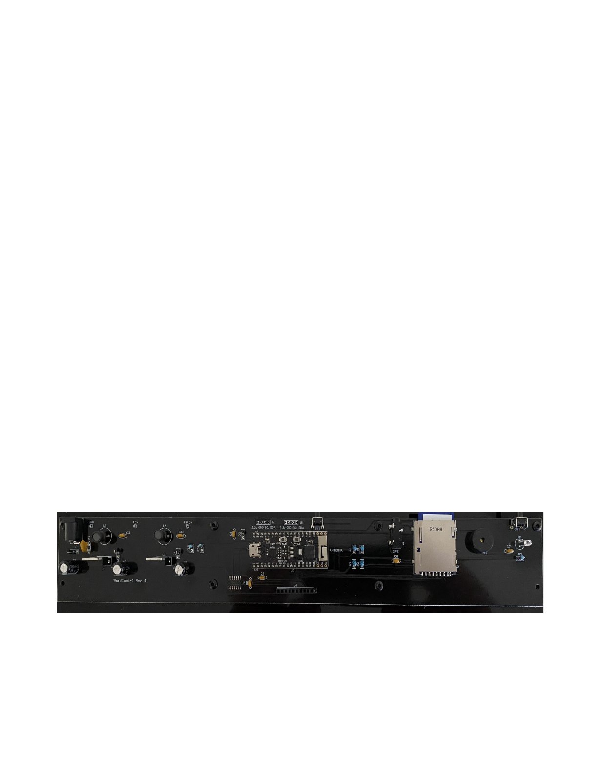
• Build the power 5v supply on the main board. Install J1, F1, C1, C2, C3, D1, D2, L1, and
U1. Note that C1, C2, D1, and D2 must be installed in the direction noted on the board.
• Connect a 12v-18v power supply with a center positive, 2.1mm connector to J1, and
check the test point for 5v. Do not continue assembly if 5v is not present at the test point.
• Build the 10.5v power supply on the main board. Install C9, C10, D4, R29, R30, L2, and
U8. Note that C9 and D4 must be installed in the direction noted on the board.
• Connect the power supply, and check the test point for approximately 10.5v. Do not
continue assembly if approximately 10.5v is not present at the test point.
• Install the remaining components on the main board. Save Q1, the ambient light sensor,
for last. Start with U3, the 74AHC125D, 14-SOHC chip. The line or dot on one side of
the chip must be installed toward the cutout on one side of the silkscreened pattern. The
best way to install a surface mount chip is to add a very small amount of solder to one
of the corner pads on the board. Then quickly and carefully solder the corresponding pin
to the pad. Check the alignment of all 14 pins and if correct, solder the opposite corner
pin. Check the alignment again, then solder the remaining pins quickly and carefully.
Always use a magnifier to check for solder bridges and bad solder joints. Note that the
LM2576 marked ‘ADJ’ must be installed at U8. These two parts are not interchangeable.
• Install the SD card connector next. It is not necessary to solder the three small leads on
the side of the board closest to SW1. Solder quickly and carefully. Plastic parts can be
damaged by too much heat. Then install J3, the GPS connector.
• The ambient light sensor, Q1, should be installed about 10mm above the board. The
shorter lead goes toward the back of the board.
• Cut the 40 pin female header into two, 17 pin pieces. Install at the U2 location.
DO NOT solder the microcontroller to the board!
• Install the remaining parts to the main board. J6 and J7 are not used.
• Insert the microcontroller, U2, into the headers, aligning the direction of the USB
connector and the antenna with the marks on the board.

WordClock-2 Assembly Guide 4/20/20 Version 1.3
Page 4
Step 2 – Build the Display Board
All parts are installed on the back of the board (silk screen side) except for the
background lighting LEDs, and the alphanumeric displays.
For ease of assembly, parts should be installed in the order noted here.
• Install LED11-LED34 (LED11-LED42). Follow the same procedure noted above to install
surface mount parts. The LEDs must be soldered quickly and carefully. Note the
direction. Align the angled corner with the mark on the upper-left corner of the silkscreen.
If an LED must be removed, be careful not to damage the board. The best way to do this
is to cut the LED horizontally with diagonal cutters, exposing the pins. Then lift each pin
to unsolder individually.
• Install surface mount resistors at R6-R9 (Not Used). The exact value depends on the
color of the display. The correct value is supplied with the displays. These resistors are
used to equalize the brightness between the display and colons. See the bill of materials
for the correct value.
• Install C11-C14 (C11-C15), the surface mount capacitors, and C15 for the eight-digit
version. They are usually unmarked, tan colored components.
• Install J5, the 90-degree male connector, to the back of the display board. Solder one
pin first, then check the alignment to verify that the pins are parallel to the board.
• Cut the pin headers to size, and fit them to display LED1-LED6 (LED1-LED8). Each LED
uses a 9-pin header on top, and a 10 pin header on the bottom. Use masking tape to
hold the headers in place. Position the display board upside down on a flat surface, and
solder one pin on each header. Check that the headers are perpendicular to the display
board and adjust if necessary. Then solder the remaining pins.
If individual pins are provided, install them on each display before soldering. Use
masking tape to hold the displays. Then solder all pins.
• Solder U4-U9 (U4-U10) to the back of the display board. Note the direction. Pin one is
up on all ICs except U6. Again, follow the above procedure to install surface mount

WordClock-2 Assembly Guide 4/20/20 Version 1.3
Page 5
parts.
• Solder resistor arrays R10-R12, to the back of the board. Note the polarity. The mark on
the arrays must be aligned with the square side of the silk screen. Pin 1 is up on R10-
R11, down on R12.
• Install LED7-LED10 (skip this step), the colon LEDs. Don’t solder yet. The short pin goes
toward the top of the display board. Turn the display board over so it is face down. Make
sure the LEDs are touching the work surface, and solder one lead on each LED. Check
the alignment and adjust as necessary. Solder the second lead of each LED.
Step 3 – Final Assembly
• Install four, 10mm standoffs into the holes on the bottom of the main board on the side
with the buttons, using four screws.
• Install two standoffs into the holes on the bottom of the main board on the front side, on
each outer edge, with 90-degree brackets. Put the screws through the short side of the
bracket, then the board, and screw into the standoffs. Install screws and standoffs only,
onto the six remaining holes.
• Plug the display board into the main board. The brackets should be behind the display
board. Install two screws and nuts to secure it to the brackets
• Remove protective film from the alphanumeric displays.
This completes WordClock-2 assembly. Refer to the User Manual for setup and operation.

WordClock-2 Assembly Guide 4/20/20 Version 1.3
Page 6
Bill of Materials
Reference
Qty
Part
Value
Note
C1-C2, C9
3
Capacitor
330uf 25v-
50v
electrolytic
C3-C8, C10
7
Capacitor
100nf
through hole
C11-C14
4
Capacitor
100nf
surface mount
D1
1
Diode
1N4001-
1N4007
supplied value may vary
D2-D4
3
Zener Diode
1N5819
zener diode
F1
1
Poly Fuse
.5A – 1A
J1
1
Power Jack
2.1mm power jack
J2
1
SD Card
Connector
DM1AA-SF-PEJ SD card jack
J3
1
GPS Jack
3.5mm SMD GPS jack
J4
1
Header
HDR-1x10 female
J5
1
Header
HDR-1x10 male
J6, J7
Not used
L1, L2
2
Inductor
100uh
LED1-LED6
(LED1-
LED8)
6(8)
Display
16 SEGMENT LED 2.3” CC
LED7-
LED10(Not
Used)
4
Colon
5mm LED color matched to display
LED11-
LED34
(LED11-
LED43)
24
(32)
Backlight
APA102 LED
PZ1
1
Buzzer
buzzer
Q1
1
Sensor
TEPT4400
light sensor
R1-R2
2
Resistor
4.7k ¼ watt
yellow-violet-red-gold or
Yellow-violet-black-brown-gold

WordClock-2 Assembly Guide 4/20/20 Version 1.3
Page 7
R3-R4
2
Resistor
10k
brown-black-orange-gold or
Brown-black-black-red-gold
R5
1
Resistor
120k
brown-red-yellow-gold or brown-red-black-
orange-gold
R6-R9 (Not
Used)
4 (0)
Resistor SMD
230R or
315R
Orange and Super Red – 315R, Others
230R (supplied value may vary slightly)
R10-R12
3
Resistor
4.7k
Resistor array
R13, R14,
R17, R18,
R24, R28
6
Resistor SMD
270R or
180R
Orange and Super Red – 270R, Others
180R (supplied value may vary slightly)
R15, R16,
R19, R20,
R21, R22,
R23, R25,
R26, R27
10
Resistor SMD
150R or
90.9R
Orange and Super Red – 150R, Others
90.9R (supplied value may vary slightly)
R29
1
Resistor
9k
white-black-red-brown or white-black-
black-brown-brown
R30
1
Resistor
1.2k
brown-red-red-brown or brown-red-black-
brown-brown
SW1-SW2
2
Button
90 degree pushbutton
U1
1
IC
LM2576T5.0
Not interchangeable with U8!
U2
1
Microcontroller
ESP32-
PICO-KIT
Programmed with WordClock firmware
U3
1
IC
74AHC125D
U4
1
IC
HT16K33
U5-U6
2
IC
TBD62783
U7
1
IC
ULN2803
U8
1
IC
LM2576ADJ
Not interchangeable with U1!
U9 (U9-
U10)
1 (2)
IC
74HC04D
1
Header
40 pins. Cut to 2x17 for microcontroller
3 or
120
(4 or
160)
Pin Header
3 (4) Headers with 40 pins each, or
individual pins
2
Bracket
Keystone 4326

WordClock-2 Assembly Guide 4/20/20 Version 1.3
Page 8
8
Standoff
Threaded 10mm
10
Screw
M3 8mm
2
Nut
M3
1
SD Card
Programmed with WordClock language
database

WordClock-2 Assembly Guide 4/20/20 Version 1.3
Page 9
Schematic

WordClock-2 Assembly Guide 4/20/20 Version 1.3
Page 10

WordClock-2 Assembly Guide 4/20/20 Version 1.3
Page 11
Warranty Terms and Conditions
This software and hardware product is Copyright (C) 2019 by Mitchell Feig. It is exclusively
distributed by StocksClocks LLC. All Rights Reserved. StocksClocks warrants that for a period
of 90 days following delivery, kit parts will (a) perform in accordance with published
specifications, and (b) will be free from defects in materials and workmanship. In the event a kit
part does not meet this warranty, subject to the conditions set forth in these terms and
conditions, StocksClocks sole obligation will be, at its election, to repair or replace the kit part
in question. We may require return of the part for examination and replacement. Replacement
will be completed at the sole discretion of StocksClocks, after examining the returned part.
Correct assembly is the responsibility of the builder.
StocksClocks MAKES NO OTHER WARRANTIES, EXPRESS OR IMPLIED, AND ALL
IMPLIED WARRANTIES OF MERCHANTABILITY, NON-INFRINGEMENT, AND FITNESS
FOR A PARTICULAR PURPOSE ARE HEREBY DISCLAIMED. IN NO EVENT WILL
Stocksclocks BE LIABLE FOR PUNITIVE, SPECIAL OR CONSEQUENTIAL DAMAGES, OR
FOR AN AMOUNT IN EXCESS OF THE PURCHASE PRICE OF THE DEFECTIVE
Stocksclocks PART OR PRODUCT.
This manual suits for next models
1
Table of contents
Other Angry Electrons Clock manuals
Popular Clock manuals by other brands

Renesas
Renesas VersaClock 6E Series Register Descriptions and Programming Guide

Lowrance
Lowrance LDT-3003 Installation and operation instructions

GREENHURST
GREENHURST 4372 quick start guide

Thermo
Thermo SH-TM-247 instruction manual

Kings Power
Kings Power KP-210 Operation manual

Blumfeldt
Blumfeldt Paddington Early Bird manual

LIELONGREN
LIELONGREN LLR010B user manual

Dakota Digital
Dakota Digital HLC-69F-MUS installation manual

Learning Resources
Learning Resources Time Tracker LER6999 Use and care instructions

Marathon
Marathon CL030055 Series manual

RGB
RGB 301-05-02 Operation and maintenance manual

Bodet
Bodet Style Mondiale Installation and operation manual