Simoco SDB680 User manual

Simoco Wireless Solutions Simoco Wireless Solutions
Field House,
Uttoxeter Old Road,
Derby.
DE1 1NH.
Tel: +44 (0) 1332 375500
Fax: +44 (0) 1332 375501
www.simocowirelesssolutions.com
1270 Ferntree Gully Road,
Scoresby Victoria,
3179
Australia.
Tel: +61 (0)3 9730 3999
Fax: +61 (0)3 9730 3988
www.simocowirelesssolutions.com
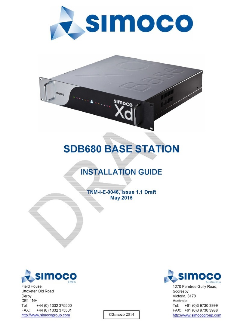
SDB680 BASE STATION
INSTALLATION GUIDE
ISSUE 1.2
Document Number: TNM-I-E-0046
Unrestricted
Date: October 2018
© Simoco Wireless Solutions 2018

This page has been intentionally left blank.
Doc Number: TNM-I-E-0046 ISSUE 1.2 Page 2

PREFACE
Before installation, commissioning or operation, this document should
be read in full. In addition, user should also read the Simoco Digital
Management Terminal (SDMT) User Manual [2], as the SDMT software
application is used extensively in the configuration procedures con-
tained within this installation guide.
DECLARATION
This Installation Guide covers the SDB680 50W Base Station for installation in Wall
Mount and Rack Mount variants.
Any performance figures quoted are subject to normal manufacturing and service
tolerances. The right is reserved to alter the equipment described in this manual in the
light of future technical development.
Changes or modifications not expressly approved by the party responsible for
compliance could void the user’s authority to operate the equipment.
COPYRIGHT
All information contained in this document is the property of Simoco. All rights are
reserved. This document may not, in whole or in part, be copied, photocopied,
reproduced, translated, stored, or reduced to any electronic medium or machine-
readable form, without prior written permission from Simoco.
COMPUTER SOFTWARE COPYRIGHTS
The AMBE+2TM voice coding Technology embodied in this product is protected by
intellectual property rights including patent rights, copyrights and trade secrets of
Digital Voice Systems, Inc. This voice coding Technology is licensed solely for use
within this Communications Equipment. The user of this Technology is explicitly
prohibited from attempting to extract, remove, decompile, reverse engineer, or
disassemble the Object Code, or in any other way convert the Object Code into a
human-readable form. U.S. Patent Nos. #6,912,495 B2, #6,199,037 B1, #5,870,405,
#5,826,222, #5,754,974, #5,701,390, #5,715,365, #5,649,050, #5,630,011,
#5,581,656, #5,517,511, #5,491,772, #5,247,579, #5,226,084 and #5,195,166.
DISCLAIMER
There are no warranties extended or granted by this document. Simoco accepts no
responsibility for damage arising from use of the information contained in the
document or of the equipment and software it describes. It is the responsibility of the
Doc Number: TNM-I-E-0046 ISSUE 1.2 Page 3

user to ensure that use of such information, equipment and software complies with
the laws, rules and regulations of the applicable jurisdictions.
EQUIPMENT AND MANUAL UPDATES
In the interests of improving the performance, reliability or servicing of the equipment,
Simoco reserves the right to update the equipment or this document or both without
prior notice.
ERRORS AND OMISSIONS
The usefulness of this publication depends upon the accuracy and completeness of the
information contained within it. Whilst every endeavour has been made to eliminate
any errors, some may still exist. It is requested that any errors or omissions noted
should be reported to Simoco Wireless Solutions:
Doc Number: TNM-I-E-0046 ISSUE 1.2 Page 4

DOCUMENT HISTORY
This section provides you with details about the changes that are in each version of
this document.
Ver
No Comments Technical
Author Reviewer Approver
1.0 Initial Issue Peter
Jones
1.1
FCC Exposure and Compliance
Warnings added to WARNINGS
page and minor changes to Sup-
port Page and Electrical Con-
nections.
Peter
Jones
1.2 Minor Updates Mark
Preston
RELATED DOCUMENTS
1. TNM-M-E-0047. SDB680 Base Station – Service Manual.
2. TNM-U-E-0112. Simoco Digital Management Terminal – User Manual.
3. TNM-U-E-0120. Simoco IP Configuration Tool – User Manual.
To order printed copies of this or any of the above publications, please contact
Simoco. See the Support page for contact information.
A comprehensive list of documentation is available for download on the Simoco
website www.simocowirelesssolutions.com via the Partner Portal.
Doc Number: TNM-I-E-0046 ISSUE 1.2 Page 5

TABLE OF CONTENTS
PREFACE 3
DECLARATION 3
COPYRIGHT 3
COMPUTER SOFTWARE COPYRIGHTS 3
DISCLAIMER 3
EQUIPMENT AND MANUAL UPDATES 4
ERRORS AND OMISSIONS 4
DOCUMENT HISTORY 5
RELATED DOCUMENTS 5
LIST OF FIGURES 9
PERSONAL SAFETY 11
SAFETY PRECAUTIONS 11
HAZARDOUS SUBSTANCES 11
WARNINGS 12
HEAVY EQUIPMENT 12
RADIO FREQUENCY RADIATION (EU) 12
DANGEROUS VOLTAGES 12
HUMAN EXPOSURE TO RADIO FREQUENCY RADIATION (FCC) 12
FCC PART 15 COMPLIANCE 13
EQUIPMENT SAFETY 14
INSTALLATION AND MAINTENANCE 14
CAUTIONS 14
MAINTENANCE PRECAUTIONS 14
WASTE ELECTRICAL AND ELECTRONIC EQUIPMENT (WEEE) NOTICE 15
SIMOCO SUPPORT 16
ABBREVIATIONS 18
RECOMMENDED TOOLS & TEST EQUIPMENT 23
TOOLS 23
TEST EQUIPMENT 23
CABLES 23
MATERIALS 23
SOFTWARE 23
1 ENVIRONMENTAL CONDITIONS 24
OPERATING TEMPERATURE RANGE 24
HUMIDITY 24
DUST AND DIRT 24
VENTILATION 24
MOUNTING LOCATION 25
2 POWER SUPPLIES 27
2.1. POWER SUPPLY OPTIONS 27
2.2. PSU TRAY 27
2.3. AC POWER CORD 27
Doc Number: TNM-I-E-0046 ISSUE 1.2 Page 6

2.4. DC POWER CONNECTOR 28
3 ELECTRICAL CONNECTIONS 29
3.1. GENERAL 29
3.2. REAR PANEL CONNECTORS 29
3.2.1. Tx/Rx Connections 30
3.2.2. Power Connection 30
3.2.3. Earth Point 31
3.2.4. P3 USB A Dual 31
3.2.5. P4 USB B 31
3.2.6. P5 Ethernet 31
3.2.7. S2 Serial Port 32
3.2.8. S1 Facilities Connector 32
4 WALL MOUNT INSTALLATION 34
TOOLS, TEST EQUIPMENT AND MATERIALS REQUIRED 34
4.1. INSTALLATION OF THE WALL MOUNT UNIT 34
4.2. ELECTRICAL CONNECTIONS 36
5 RACK MOUNT INSTALLATION PROCEDURE 37
5.1. TOOLS, TEST EQUIPMENT AND MATERIALS REQUIRED 37
5.2. RACK PREPARATION 37
5.3. FITTING THE SDB680 BASE STATION 38
5.4. ELECTRICAL CONNECTIONS 38
6 CONFIGURATION OF NEW TIER II BASE STATION 39
TOOLS, TEST EQUIPMENT AND MATERIALS REQUIRED 39
6.1. SDB680 PREPARATION 39
6.2. SDMT INSTALLATION AND PREPARATION 40
6.3. INSTALLING THE SIMOCO IP CONFIGURATION SERVER 40
6.4. IP ADDRESS CONFIGURATION 40
6.5. CONFIGURING THE DMR BASE 41
7 CONFIGURATION OF NEW TIER III BASE STATION 43
TOOLS, TEST EQUIPMENT AND MATERIALS REQUIRED 43
7.1. 4.1 SOFTWARE LICENCES 43
7.2. SDB680 PREPARATION 44
7.3. SDMT INSTALLATION AND PREPARATION 44
7.4. INSTALLING THE SIMOCO IP CONFIGURATION SERVER 44
7.5. 4.5 IP ADDRESS CONFIGURATION 44
7.6. CONFIGURING THE DMR BASE 45
7.6.1. Platform and Application Software Update 45
7.6.2. Software Licence Update 47
7.6.3. Configuration Creation and Upload 47
7.6.4. 4.6.4 Enable Bases 48
8 BASE CONFIGURATION TIER II TO TIER III 49
TOOLS, TEST EQUIPMENT AND MATERIALS REQUIRED 49
8.1. TIER III BASE PREREQUISITES 49
8.2. SOFTWARE LICENCES 49
8.3. IP ADDRESS CONFIGURATION 50
8.4. CONFIGURING THE DMR BASE 50
Doc Number: TNM-I-E-0046 ISSUE 1.2 Page 7

8.4.1. Platform and Application Software Update 50
8.4.2. Tier III IP Address Configuration 51
8.4.3. Software Licence Update 52
8.4.4. Configuration Creation and Upload 53
8.4.5. Enable New Tier III Base 53
9 BASE CONFIGURATION TIER III TO TIER II 54
TOOLS, TEST EQUIPMENT AND MATERIALS REQUIRED 54
9.1. TIER II BASE PREREQUISITES 54
9.2. IP ADDRESS CONFIGURATION 54
9.3. CONFIGURING THE DMR BASE 55
9.3.1. Changing the Platform and Application Software 55
Doc Number: TNM-I-E-0046 ISSUE 1.2 Page 8

LIST OF FIGURES
Figure 1: Layout of Rear Panel. 29
Figure 2: 2-pin IP67 DC Power Connector. 30
Figure 3: Mounting holes drilling template (dimensions in mm). 35
Figure 4: Wall Mount Assembly. 35
Figure 5: Keyhole Standoff mounting locations. 36
Figure 6: Base Station secured to Wall Mount. 36
Figure 7: Interface Selection screen. 40
Figure 8: IP Configuration Tool main screen 41
Figure 9: Base configuration page – Base Settings tab. 41
Figure 10: Write Base(s) page. 42
Figure 11: Interface Selection screen. 45
Figure 12: IP Configuration Tool main screen. 45
Doc Number: TNM-I-E-0046 ISSUE 1.2 Page 9

LIST OF TABLES
Table 1: Rear Panel Connections. 29
Table 2: DC Power Connector Pin-outs. 30
Table 3: USB Type A Connector Pin-outs. 31
Table 4: USB Type B Connector Pin-outs. 31
Table 5: Ethernet RJ45 Connector Pin-outs. 31
Table 6: S2 Serial Port Connector Pin-outs. 32
Table 7: Facilities Connector Pin-outs. 33
Doc Number: TNM-I-E-0046 ISSUE 1.2 Page 10

PERSONAL SAFETY
SAFETY PRECAUTIONS
These Safety Precautions, Warnings and Cautions advise personnel of specific hazards
which may be encountered during the procedures contained in this document and that
control measures may be required to prevent injury to personnel, and damage to
equipment and/or the environment.
Before commencing the installation or any maintenance of the equipment covered in
this manual, personnel are to acquaint themselves with all risk assessments relevant
to the work site and the task. They must then comply with the control measures
detailed in those risk assessments.
References covering safety regulations, health hazards and hazardous substances are
detailed under the WARNINGS section below. These are referred to in the tasks, when
encountered.
Adequate precautions must be taken to ensure that other personnel do not activate
any equipment that has been switched off for maintenance. Refer to the relevant
Electrical Safety Regulations appropriate to the country of operation.
Where dangerous voltages are exposed during a task, safety personnel are to be
provided as detailed in the relevant Electrical Safety Regulations. Where safety
personnel are required for any other reason, management are to ensure that the
personnel detailed are aware of the hazard and are fully briefed on the action to be
taken in an emergency.
Where equipment contains heavy components or units that require lifting, lowering,
pulling or pushing operations to be performed on them during maintenance tasks, all
managers and tradesmen are to be conversant with the Manual Handling Operations
Regulations.
HAZARDOUS SUBSTANCES
Before using any hazardous substance or material, the user must be conversant with
the safety precautions and first aid instructions:
• On the label of the container in which it was supplied.
• On the material Safety Data Sheet.
• In any local Safety Orders and Regulations.
Doc Number: TNM-I-E-0046 ISSUE 1.2 Page 11

WARNINGS
HEAVY EQUIPMENT
WARNING
HEAVY EQUIPMENT. THE WEIGHT OF A FULLY ASSEMBLED SDB680 BASE
STATION IN THE WALL MOUNT IS APPROX 10 KG (2 MEN TO LIFT). REFER
TO THE MANUAL HANDLING OPERATIONS REGULATIONS 1992.
RADIO FREQUENCY RADIATION (EU)
WARNING
RADIO FREQUENCY (RF) RADIATION. A RF RADIATION HAZARD EXISTS IN
THIS EQUIPMENT. TO AVOID RF INJURY, DO NOT TOUCH THE ANTENNA
WHEN THE TRANSMITTER IS IN USE. DO NOT OPERATE TRANSMITTER
WITH ANTENNA DISCONNECTED. REFER TO EU DIRECTIVE 2004/40/EC
DATED 29 APRIL 2004.
DANGEROUS VOLTAGES
Dangerous voltages exist in this equipment, for the appropriate Safety precautions,
refer to the relevant Electrical Safety Regulations appropriate to the country of
operation.
WARNING
THIS EQUIPMENT MUST TO BE CONNECTED TO A MAINS POWER SUPPLY
THAT HAS A SAFETY EARTH CONNECTION.
WARNINGS
DO NOT CONNECT THE ELECTRICITY SUPPLY UNTIL THE INSTALLATION IS
COMPLETE
DISCONNECT THE MAINS ELECTRICITY SUPPLY BEFORE WORKING ON AN
OPEN WALL MOUNT OR POWER SUPPLY UNIT TRAY
HUMAN EXPOSURE TO RADIO FREQUENCY RADIATION
(FCC)
WARNING
TO COMPLY WITH THE MAXIMUM PERMISSIBLE EXPOSURE (MPE) LIMITS
REFERENCED IN 47 CFR 1.1310 TABLE 1, THE FOLLOWING MINIMUM SAFE
Doc Number: TNM-I-E-0046 ISSUE 1.2 Page 12

OPERATING DISTANCES MUST BE OBSERVED:
150 MHz to 174 MHz: 1.8 m
406.1 MHz to 480.0 MHz: 1.52 m
480 MHz to 512 MHz: 1.49 m
FCC PART 15 COMPLIANCE
THIS DEVICE COMPLIES WITH PART 15 OF THE FCC RULES. OPERATION IS
SUBJECT TO THE FOLLOWING TWO CONDITIONS: (1) THIS DEVICE MAY
NOT CAUSE HARMFUL INTERFERENCE; AND (2) THIS DEVICE MUST
ACCEPT ANY INTERFERENCE RECEIVED, INCLUDING INTERFERENCE THAT
MAY CAUSE UNDESIRED OPERATION.
Doc Number: TNM-I-E-0046 ISSUE 1.2 Page 13

EQUIPMENT SAFETY
INSTALLATION AND MAINTENANCE
The SDB600 Series Base Stations should only be installed and maintained by qualified
personnel.
CAUTIONS
CAUTION
Before drilling any walls, first check for any buried cables or pipes.
CAUTION EQUIPMENT DAMAGE.
When the SDB680 Base Station is installed into a rack, DO NOT use the
front panel attachment points to support the full weight of the
equipment or damage to the equipment may result. Suitable shelves or
supports MUST be provided to support the body of the base station
along the length of each side.
MAINTENANCE PRECAUTIONS
CAUTION
Electrostatic Discharge Sensitive Devices (ESDS Devices). This equipment
contains ESDS Devices, the handling procedures detailed in BS EN
61340-5-1:2007 or ANSI/ESD S20.20-1999 are to be observed.
Doc Number: TNM-I-E-0046 ISSUE 1.2 Page 14

WASTE ELECTRICAL AND ELECTRONIC
EQUIPMENT (WEEE) NOTICE
The Waste Electrical and Electronic Equipment (WEEE) Directive
became law in most EU countries during 2005. The directive
applies to the disposal of waste electrical and electronic equipment
within the member states of the European Union.
As part of the legislation, electrical and electronic equipment will
feature the crossed out wheeled bin symbol (see image at left) on
the product or in the documentation to show that these products
must be disposed of in accordance with the WEEE Directive.
In the European Union, this label indicates that this product should not be disposed of
with domestic or “ordinary” waste. It should be deposited at an appropriate facility to
enable recovery and recycling.
Doc Number: TNM-I-E-0046 ISSUE 1.2 Page 15

SIMOCO SUPPORT
At Simoco we welcome your comments, feedback, and suggestions. Departmental
contacts have been provided for your quick reference below.
UK Customer Services
Email: customer.service@simocowirelesssolutions.com
Telephone Numbers:
UK: 08717 411 050
International: +44 (0) 1332 375 671
Fax:
UK: 08717 411 049
International: +44 (0) 1332 376 672
Sales
Email: sales@simocowirelesssolutions.com
Marketing
Email: marketing@simocowirelesssolutions.com
Australian Customer Services
Email: inquiry.aus@simocowirelesssolutions.com
Telephone Numbers:
Australia: 1300 363 607
International: +61 3 9730 3999
US Customer Services
Email:customer.service@simocowirelesssolutions.com
Technical Support
In order to streamline support requests and better serve our customers, at Simoco we
utilize a support ticket system. Every support request is assigned a unique ticket
number, which customers can use to track the progress and responses online. For
reference, Simoco provide complete archives and history of all customer support
requests. In order to use the support ticket system, a valid email address is required.
Doc Number: TNM-I-E-0046 ISSUE 1.2 Page 16

A link to the online Simoco Wirless Solutions Support Centre Ticket Tracking system is
provided www.simocowirelesssolutions.com/support
If you still require further technical assistance after raising a support ticket, please
contact us via the email addresses or via the Technical Support Helpline numbers
below.
Technical Support Email Addresses
Simoco
EMEA: technical.support@simocowirelesssolutions.com
Simoco Aus-
tralasia: inquiry.aus@simocowirelesssolutions.com
Simoco
Americas: technical.support@simocowirelesssolutions.com
Technical Support Helplines
Simoco UK and US
UK: 08717 411 040
International: +44 (0) 1332 375 671
Australia
Australia: 1300 363 607
International: +61 3 9730 3999
Doc Number: TNM-I-E-0046 ISSUE 1.2 Page 17

ABBREVIATIONS
A
ACK
Acknowledgement
AES
Advanced Encryption Standard
ATM
Automated Teller Machine
B
BER
Bit Error Rate
C
CLI
Command Line Interface
CRC
Cyclic Redundancy Check
CTS
Clear To Send
D
dBc
decibel relative to the carrier
dBi
decibel relative to the isotropic
dBm
decibel relative to the milliwat
DCE
Data Communication Equipment
Doc Number: TNM-I-E-0046 ISSUE 1.2 Page 18

DHCP
Dynamic Host Configuration Protocol
DNS
Domain Name Server
DTE
Data Terminal Equipment
E
EMC
Electro-Magnetic Compatibility
F
FCC
Federal Communications Commission
FEC
Forward Error Correction
FEP
Front End Processor
G
GPL
General Public License
H
HTTPS
Hypertext Transfer Protocol Secure
I
IP
Internet Protocol
Doc Number: TNM-I-E-0046 ISSUE 1.2 Page 19

K
kbps
kilobit per second
L
LAN
Local Area Network
LOS
Line-of-Sight
M
MAC
Media Access Control
MDIX
Medium Dependant Interface Crossover
MIB
Management Information Base
MRU
Maximum Recption Unit
MTU
Maximum Transmission Unit
N
NC
Normally Closed
NMS
Network Management System
NO
Normally Open
NTP
Network Time Protocol
Doc Number: TNM-I-E-0046 ISSUE 1.2 Page 20
Other manuals for SDB680
1
Table of contents
Other Simoco Accessories manuals
Popular Accessories manuals by other brands

Cumberland
Cumberland 300 Installation and operation manual
Vega
Vega SMART-SS0102 user manual
LSI
LSI GS320 Installer's/user's manual
Minebea Intec
Minebea Intec Pendeo PR 6204 Series installation manual
HB Products
HB Products HBX Vapor Quality sensor Installation and configuration guide

Garland
Garland GIU 3.5 KW parts list
