SimPark Easymatic-E User manual

1
Keep this installation manual in your caravan!
Easymatic-E
1. List of parts 2
2. Connection bar 2
3. Mounting clamps 3
4. Chassis profiles and dimensions 4
5. Electric connections 5 / 6
6. Users manual 7 / 8
7. Safety precautions 9
8. Warranty conditions 11
INSTALLATION
MANUAL
2
1 x Left and right mover unit
1 x Connection bar, 2 x mounting clamps including fitings
1 x Remote control with 2 x AA batteries, 1 x HD Controller, antenna and green connector set
1 x 1.5 meter red cable 10 mm2 / 1x 1 meter black cable 10 mm2
18 x Screws 4 x 20 mm
4 x Yellow electrical terminals for the motor cables
6 x Black Tie wraps
1 x 5 meter black flexible protection hose
1 x Caution sticker "Release rollers"
1 x 1 meter red cable 1 mm2
1 x Power main switch with 3 x solder terminals
1 x Socket screw driver
1 x 4 meter purple cable 1 mm2
1 x 4 meter brown cable 1 mm2
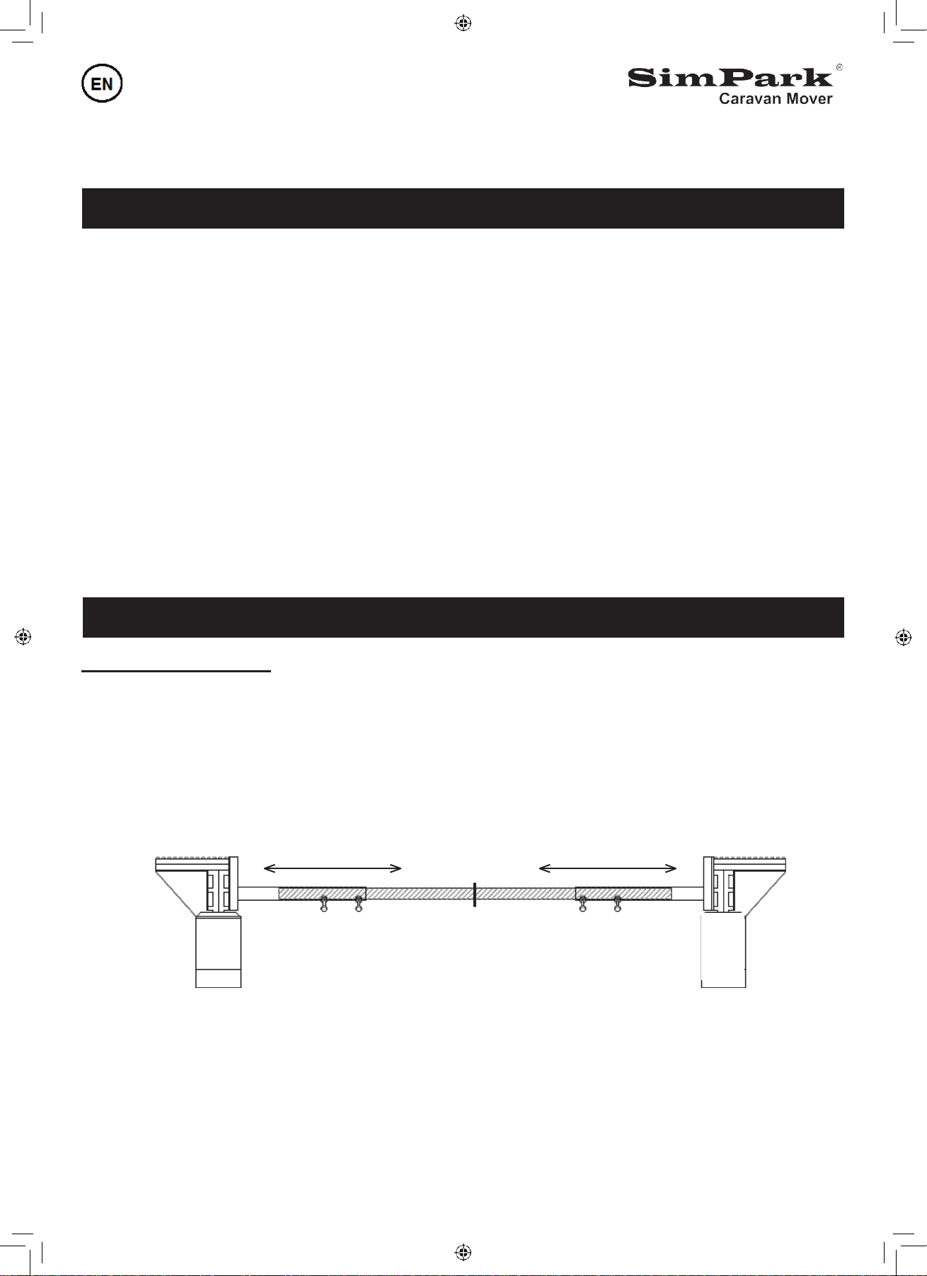
Installation instructions
•Measure the length of the connection bar and mark the center of the connection bar (75 cm)
•Measure the track width of the caravan
•Connect the left and rightmover unit together by means of the connection bar and make sure that the marked
point on the connection bar is located in the middle. (See fg.1)
•Set the mover units on the measured track width
Fig. 1
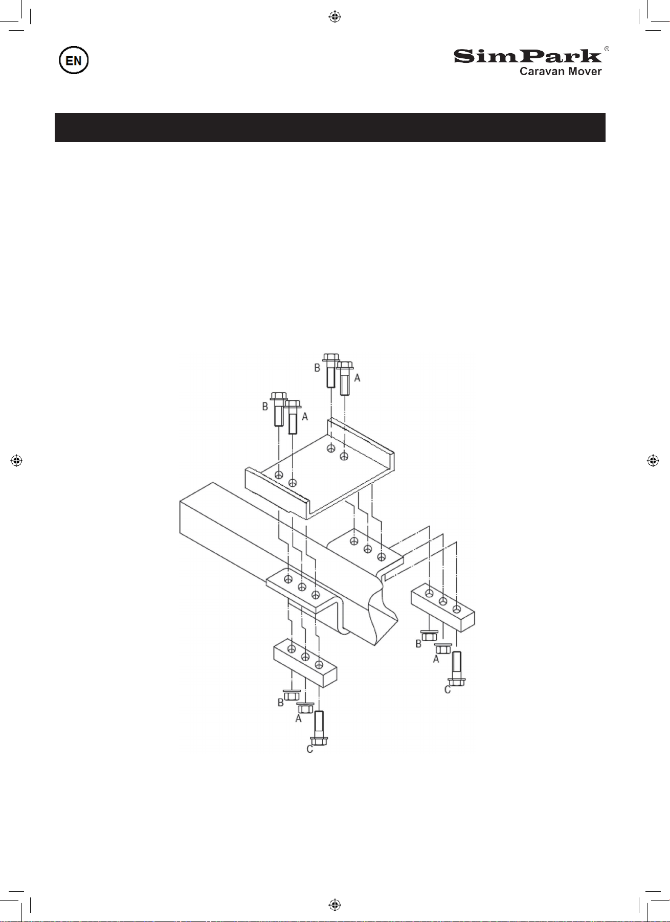
•Place the mounting clamps (see fg. 2 ) on the sub-frame and add the top plate.
•Use a support to press the movers to the chassis of the caravan.
•Slide the mounting clamps aside to the caravan chassis and tighten the clamps as per instructions
If necessary, SimPark has several mounting plates for different types of chassis in stock
2. CONNECTION BAR
1.PARTS LIST
L. max = 2450 mm
Mark
L. min = 1870 mm
D
D
SimPark
SimPark
3
N
AND
TIN
•Be sure that the distance between the drive-rollers and the caravan tyres is 20 mm.
•When the system isinonestraightlineandthedistancebetweenthe drive-rollersandtyresis still 20 mm,
you can tighten the bolts A and B using a torque of 70 Nm.
Note: the distance between the drive-rollers and tyres may change when the caravan is placed on the
ground again, please check if the distance is still 20 mm.
•When the distance is OK, tighten the bolts C using a torque of 70Nm, these bolts ensure that the system
cannot slide backwards.
•Tighten the bolts D of the Connection Bar (see Fig.1) with a torque of 25 Nm.
Fig. 2
3.MOUNTING CLAMPS

4
4. CHASSIS
PROFILES
AND
DIMENSIONS
Fig. 3
Vario III
chassis
Vario IV plate
Fig. 4
Hobby I chassis
Fig. 5
L en U profile
caravan chassis
Fig. 6
Dimensions
SimPark® caravan
mover
5
☞
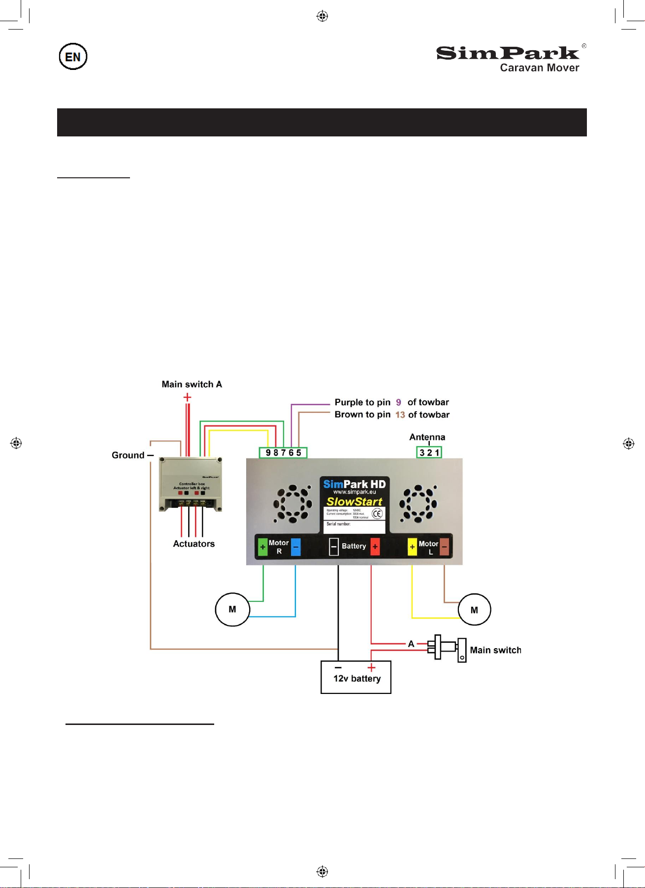
5.ELECTRIC CONNECTIONS
IMPORTANT!
•To prevent short circuits during installation, make sure that the battery is not connected.
•
Place the Controller in the caravan as close as possible near the battery. Place the antenna in a vertical
position. The connection points on the Controller are clearly marked, (see fg.13)
The Battery positive cable is RED and the negative cable is BLACK. The green and yellow cables are
the positive connections of the motors, brown and blue cables are the negative connections of the motors.
•Lead the cables through the supplied black flexible protective tube and tie them up firmly against the
chassis, use the supplied Tie wraps
•The 12 volt main power cables for the Controller are clearly marked with RED + and BLACK -
Attention, shorten the motor cables is only allowed, if the length of both cables are the same.
The colors of the motor cables are paired, do not change them.
If the main power cables are wrongly connected, the Controller will be destroyed immediately
Fi
g.
7
Easymatic-E safety function
•The brown and purple cable goes to the Caravan plug no.13 (brown) & no.9 (purple) of the towbar socket
•This safety function prevents driving away with the drive-rollers pressed on the tires
☞
6
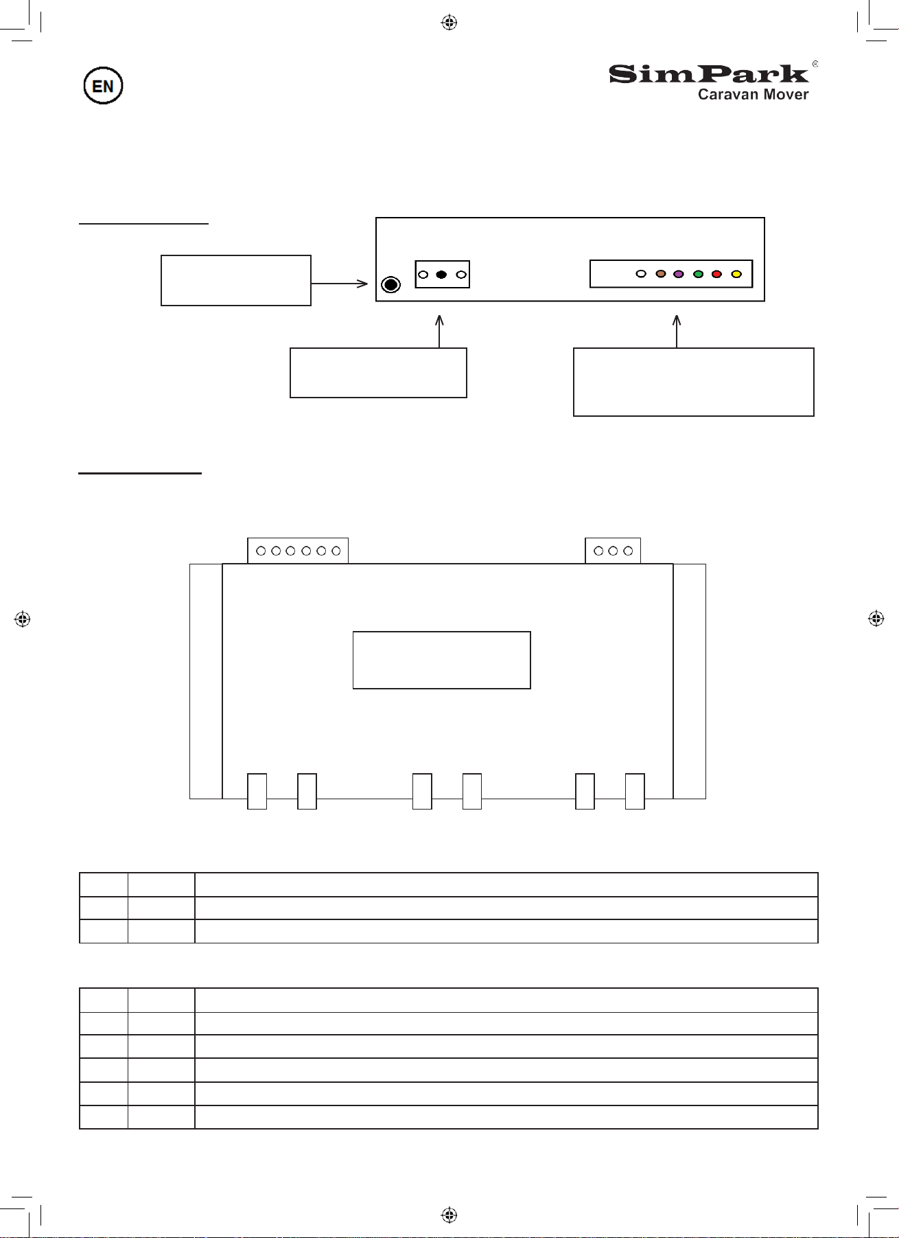
Multi connector safety function
Pin 6 of controller to pin 9 of
towbar socket (12 volt)
Antenna:
Pin no.2 is the antenna
Pair button for the
remote controller
Rear
view
receiver
Fig. 8
Top view receiver
Fig. 9
Pinnumber
9 8 7 6 5 4
Pinnumber
3 2 1
Antenna connections
(see fig. 9)
Pin 1
Not in use
Pin 2
Signal Antenna: black supplied copper wire or flying lead of maximum 52.5 cm.
Pin 3
Not in use
Pin connections
(see
fig.
9)
Pin 4
Not in use
Pin 5
GND
Brown cable: to pin 13 of the towbar socket (ground)
Pin 6
12 volt
Purple cable: to pin 9 of the towbar socket (safety function)
Pin 7
Impuls
Green cable: retract the drive-rollers from the tyres
Pin 8
12 volt
Red cable: to 12 volt + of battery
Pin 9
Impuls
Yellow cable: pressing the drive-rollers on the tyres
Motor
L
-
+
Battery
-
+
Motor
R
-
+
Controller

6.USERS MANUAL
7
☞
If you use a caravan mover for the first time, we recommend you to read the following
instructions carefully to ensure an optimal and safely use of the caravan mover.
Fig.10
Functions remote control
Direction of travel
Forwards
Right forwards
Left backwards
Left forwards
Right backwards
Backwards
Enable drive-rollers Retract drive-rollers
On/Off
Drive-rollers enable
Switch on the remote control, the red light starts to blink. Press the button "arrow up" and after 3 warning
beeps the drive-rollers will be pressed on the tires.
Drive-rollers disabled
Press the button "arrow down" and after 3 warning beeps the drive-rollers will be retracted of the tires.
Simultaneously operation of the commands
Simultaneously operation is possible with the SimPark mover.
While driving forwards it is possible to change the direction by pressing the button left or right without
releasing the forward or backward button.
It is also possible to make a 360 degree turn by pressing the buttons forwards/backwards simultaneously.

6.USERS MANUAL
8
☞
Switch on the Controller
When the remote control has been recognized by the main Controller, it will be activated.
After one beep the cooling fans start to run, the system is now ready to use.
The Controller and remote control switch off automatically after 60 seconds after the last given command.
Safety features of the Controller
Temperature protection
The Controller goes into "safety" mode when the PCB has reached a temperatureof +/- 75 degrees Celsius.
The Controller will return automatically to its program when the temperature has been decreased with 15
degrees Celsius.
Low
voltage
protection
The Controller goes into the "safety" mode when the voltage drops under 8,5 volt.
After 30 seconds the Controller will return automatically to its program when the voltage becomes
higher than 8,5 volt.
Emergency function to retract the drive-rollers
If the drive-rollers are pressed to the tyres and an electrical failure occurs, please read the next instructions.
Remove the rubber cap on the backside of the protective cover. Insert the screw-driver socket in the hole and
turn it clockwise to retract the drive-rollers from the tyres.
Status legend
Status
Number of beeps
Cooling fan
Activation of Controller
1 x
Off
Recognizing of remote controller
1 x
On
Towbar detection
1 x
Off
(Pair button is next to the antenna)
--
Error
Number of beeps
Maximum current per motor is reached
Rapid beep salvo
Motor error or bad motor cable connection
3 x
Mosfet or Driver error
4 x
Temperature PCB above 75 degrees Celsius
5 x
Battery voltage lower than 8,5V
6 x

9
7. SAFETY PRECAUTIONS
•
Practice in an area which is free from parked cars and/or other obstacles.
•Be sure that there are no children playing near the caravan during practicing.
•Before you enable the drive-rollers to the tires, be sure that no little stones or other sharp objectsare stuck
between the drive-rollers and the tires.
•Do not stay too far from the caravan, so you are always able to intervene if necessary.
A distance of 4 meters is suffcient. In the event of a malfunction, immediately switch off the system by
pressing the on/off button on the remote control or turn off the main power switch and apply the hand brake.
•If the caravan is moved down hill, please note that the drawbar of the caravan is pointed down.
This enhance the stability of the caravan during movement and prevents swaying or tippingof the caravan.
•Once the caravan is parked, pull the handbrake, only then retract the drive-rollers from the tires
•Store the remote controlin a safe and dry location out of reach of small children.
•The caravan must never be towed while the drive-rollers are pressed on the tyres, this can cause severe
damage to the drive-rollers, tyres or caravan chassis.
•Never store personal electronic equipment such as a camera, a laptop, a computer or any digital playback
devices in the same compartment as the electronic receiver or near electric cables.
•The magnetic field generated by the electrical system may damage your equipment.
•When the caravan will be stored for a long period, we recommend you to remove the two AA batteries
from the remote control. This prevents damage to the remote controlas a result of leaking batteries.
Also turn off the main power switch during storing the caravan.
•Dispose of discharged or leaking batteries in the chemical waste container intended for this purpose.
When stowing the caravan for two months or longer, we advice yo to remove the caravan battery and
charge it every 2-3 months in order to avoid a deep discharge of the battery.
•Make sure the battery is fully charged before using the mover.
•Check the pressure of your caravan tires, contact your dealer for the right tire pressure.
10
☞
Safety feature of the Easymatic-E
If you accidently forget to disable the drive-rollers from the caravan tires, the safety function ensures you that
the drive-rollers retract automatically once the caravan connector is plugged into the twobar socket.
ThisuniqueSimPark safety functionmakesitimpossibletodriveawaywith thedrive-rollers enabled.
Keep
the
drive-rollers
clean
Keep your SimPark caravan mover and in particular the drive-rollers, free of grit, sharp objects, bits of
wood,grease, mud and other contaminants. Use water and a brush to clean the drive-rollers.
Do not use a high pressure water cleaner to avoid damage to the bearings.
Technical details
Subject to technical changes
Motors
12 volt DC with gear box
Torque
25-45 Nm
Speed
18 cm per sec
Weight
35 kg
Battery
Recommended: 105 Ampere semi-traction or Enduro LI1230 Lithium Battery
Max. weight
Caravans up to 3300 kilogram on a paved underground
☞

11
8.WARRANTY CONDITIONS
The warranty period for caravan application is 4 years and for professional applications 2 years.
The warranty applies to all SimPark parts as long as the claim comes with a guranteed warranty form issued
and signed by your caravan dealer.
The warranty provides the purchaser with extra security in the event that the system does not functions properly.
It does not limit the rights of the purchaser but rather expands them. SimPark is not liable for any damage that
may result from a partial or complete malfunction of the parking assistance device.
The warranty only applies to parts that are submitted with the original purchase invoice. The warranty
becomes effective on the date of purchase. From that date the purchaser is entitled to repairs and/or
replacement under the terms of warranty.
This warranty only provides compensation for complaints resulting from deficiencies in the materials and/or
construction. Such compensation is limited tothe replacement of those parts required to complete the repair.
Under no circumstances does it provide the right to reduction of the sale price, annulment of the purchase
agreement or damage compensation for failure to comply with the terms.
A repair performed under the warranty does not extend the warranty period, nor does it entitle the owner to a
new warranty period. Warranty repairs are only performed upon submission of a dated purchase receipt.
Warranty repairs may only be performed by authorized SimPark dealers. For a list of dealers please select
"Dealers and sales points" from the menu on the website: www.simpark.eu.
The warranty provides no coverage for the following:
•The normal wear of parts, such as the drive-rollers, which occurs during normal use.
This is not applicable for drive-rollers that have been damaged during production or assembling.
•Poor functioning of the system due contamination and/or poor maintenance.
•Transport risk and damage costs.
•Electronics with serial numbers that have been removed and/or made illegible.
Damage caused by:
•Use of the system for non-standard purposes, inexpert use of the system, use contrary to the user’s manual,
Functional changes made to the system by the purchaser and/or third parties.
•Attempted repair by the purchaser and/or third parties.
•Accidents, force majeure or other risks that are uninsurable by SimPark.
Table of contents


