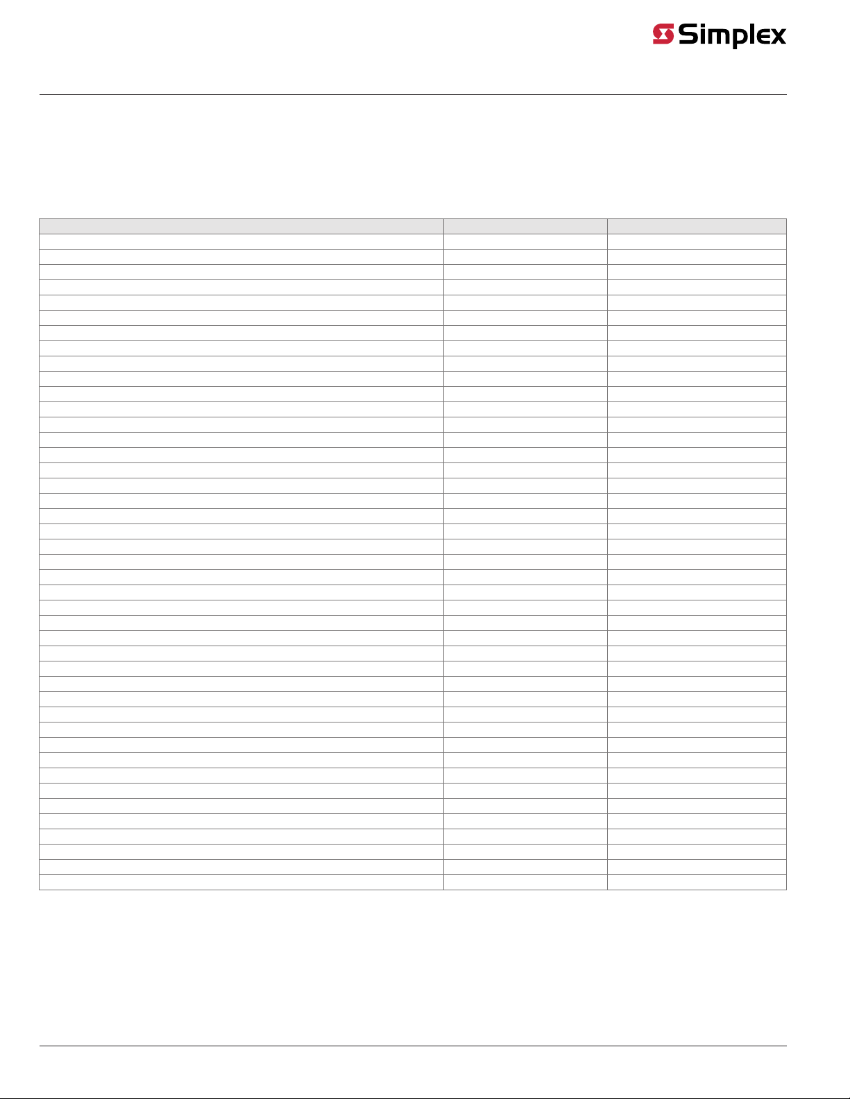
Compatible TrueAlert Devices
The following table lists compatible TrueAlert devices. All devices are rated one unit load, with the exception of the Isolator Module (4905-9929) that is
rated three unit loads.
Note:
If you are connecting devices to the 4100-5121 (Canadian) TPS, you must only attach TrueAlert compatible, ULC listed devices.
Table 3: Compatible TrueAlert Devices
Device PID Installation Document #
Horn -- Red 4901-9850 574-764
Horn – White 4901-9853 574-764
Strobe (15 cd) – Red 4904-9350 574-767
Strobe (15 cd) – White 4904-9353 574-767
Strobe (75 cd) – Red 4904-9351 574-767
Strobe (75 cd) – White 4904-9354 574-767
Strobe (110 cd) – Red 4904-9352 574-767
Strobe (110 cd) – White 4904-9355 574-767
Strobe (15 cd), Ceiling – Red 4904-9356 574-928
Strobe (15 cd), Ceiling – White 4904-9359 574-928
Strobe (75 cd), Ceiling – Red 4904-9357 574-928
Strobe (75 cd), Ceiling – White 4904-9360 574-928
Strobe (110 cd), Ceiling – Red 4904-9358 574-928
Strobe (110 cd), Ceiling – White 4904-9361 574-928
A/V (15 cd) – Red 4903-9450 574-768
A/V (15 cd) – White 4903-9453 574-768
A/V (75 cd) – Red 4903-9451 574-768
A/V (75 cd) – White 4903-9454 574-768
A/V (110 cd) – Red 4903-9452 574-768
A/V (110 cd) – White 4903-9455 574-768
A/V (15 cd), Ceiling – White 4903-9459 574-929
A/V (75 cd), Ceiling – White 4903-9460 574-929
A/V (110 cd), Ceiling – White 4903-9461 574-929
Isolator Module 4905-9929 574-769
25V/70V Speaker /V (15 cd) – Red 4903-9350 574-766
25V/70V Speaker /V (15 cd) – White 4903-9353 574-766
25V/70V Speaker /V (75 cd) – Red 4903-9351 574-766
25V/70V Speaker /V (75 cd) – White 4903-9354 574-766
25V/70V Speaker /V (110 cd) – Red 4903-9352 574-766
25V/70V Speaker /V (110 cd) -- White 4903-9355 574-766
Strobe Multi-Candela (15, 30, 75, 110) – Red 4906-9201 579-808
Strobe Multi-Candela (15, 30, 75, 110) – White 4906-9203 579-808
Strobe Multi-Candela (15, 30, 75, 110) Ceiling– White 4906-9204 579-808
A/V Multi-Candela (15, 30, 75, 110)– Red 4906-9227 579-808
A/V Multi-Candela (15, 30, 75, 110) – White 4906-9229 579-808
A/V Multi-Candela (15, 30, 75, 110) Ceiling– Red 4906-9228 579-808
A/V Multi-Candela (15, 30, 75, 110) Ceiling– White 4906-9230 579-808
Speaker/V Multi-Candela (15, 30, 75, 110) – Red 4906-9251 579-808
Speaker/V Multi-Candela (15, 30, 75, 110) – White 4906-9253 579-808
Speaker/V Multi-Candela (15, 30, 75, 110) Ceiling– White 4906-9254 579-808
Amber Strobe Multi-Candela (15, 30, 75, 110) – Red 4906-9205 579-828
Amber Strobe Multi-Candela (15, 30, 75, 110) – White 4906-9206 579-828
Amber Strobe Multi-Candela (15, 30, 75, 110) Ceiling– White 4906-9207 579-828
page 8 579-336 Rev. M
4100-5120, 4100-5121, 4100-5122 TrueAlert Power Supply Installation Instructions