S8VK-X
6
Standards
• EMI (radiated emissions) conform to Class B when this Power Supply is installed in a control panel.
• EN/IEC 61558-2-16
The S8VK-X was designed based on EN/IEC 61558-2-16.
Currently, IEC 61558-2-17 has been replaced by IEC 61558-2-16.
When certification was received for EN/IEC 60204-1 (Machinery Safety), it was necessary to go through a control transformer to the control
circuits. However, a control transformer is not always necessary for product that have been certified for the safety standard for OVCIII or for
product that use a transformer that conforms to EN/IEC 61558-2-16.
• Safety Standards for a DC Input
When DC is used, UL 60950-1, UL 62368-1, cUR (CSA 22.2 No. 60950-1), cUR (CSA C22.2 No. 62368-1), EN/IEC 60950-1, EN/IEC 62368-
1, EN 50178 and EN/IEC 61558-2-16 are applicable to safety standards.
Safety standard compliance is achievable by connecting a UL-certified fuse as specified below.
Select an external fuse that satisfies the following conditions:
S8VK-X03005-EIP, S8VK-X06012-EIP, S8VK-X06024-EIP (350 VDC or more, 6 A)
S8VK-X09024@-EIP, S8VK-X12024@-EIP, S8VK-X24024@-EIP (350 VDC or more, 8 A)
S8VK-X48024@-EIP (350 VDC or more, 12 A)
• To comply with PELV output requirements for EN/IEC 60204-1, ground the negative side of the output (-V) to a protective earth (PE).
Definitions of the Terms Under Ratings, Characteristics, and Functions
Standards
Harmonic current
emissions Conforms to EN 61000-3-2
EMI
Conducted
emissions Conforms to EN 61204-3 Class B, EN 55011 Class B
Radiated
emissions Conforms to EN 61204-3 Class B, EN 55011 Class B
EMS Conforms to EN 61204-3 high severity levels
Safety standards
UL 508, ANSI/ISA 12.12.01 (Listing) (For 30 W, 60 W, and 90 W only Class 2 Output: Per UL 1310)
CSA C22.2 No. 107.1, CSA C22.2 No. 213 (cUL) (For 30 W, 60 W, and 90 W only Class 2 Output: Per CSA C22.2 No. 223)
UL 60950-1, UL 62368-1 (Recognition) OVC II (≤3000 m) Pol2 (For 30 W, 60 W, and 90 W only LPS)
CSA C22.2 No. 60950-1, No. 62368-1 (cUR) OVC II (≤3000 m) Pol2 (For 30 W, 60 W, and 90 W only LPS)
EN 50178 OVC III (≤2000 m) OVC II (2000 m < and ≤3000 m) Pol2
EN 60950-1, EN 62368-1 OVC II (≤3000 m) Pol2 (For 30 W, 60 W, and 90 W only LPS)
EAC (TR CU 004 / 2011, TR CU 020 / 2011)
RCM (EN61000-6-4)
Korea Radio Waves Act (Law No. 10564)
Conforms to PELV (EN/IEC 60204-1)
Conforms to EN/IEC 61558-2-16
SEMI Conforms to F47-0706 (200 to 240 VAC input)
Input
conditions
Efficiency The value is when both rated output voltage and rated output current are satisfied.
Voltage range Do not use an inverter output for the product. Inverters with an output frequency of 50/60 Hz are available, but the
rise in the internal temperature of the product may result in smoking or burning. If the input is connected to a UPS,
do not connect a UPS with a square-wave output. Doing so will cause the internal temperature of the product to
increase, possibly causing smoking or burning.
Frequency
Input current The value is when both rated output voltage and rated output current are satisfied.
Leakage current The value is determined according to the Electrical Appliances and Material Safety Act.
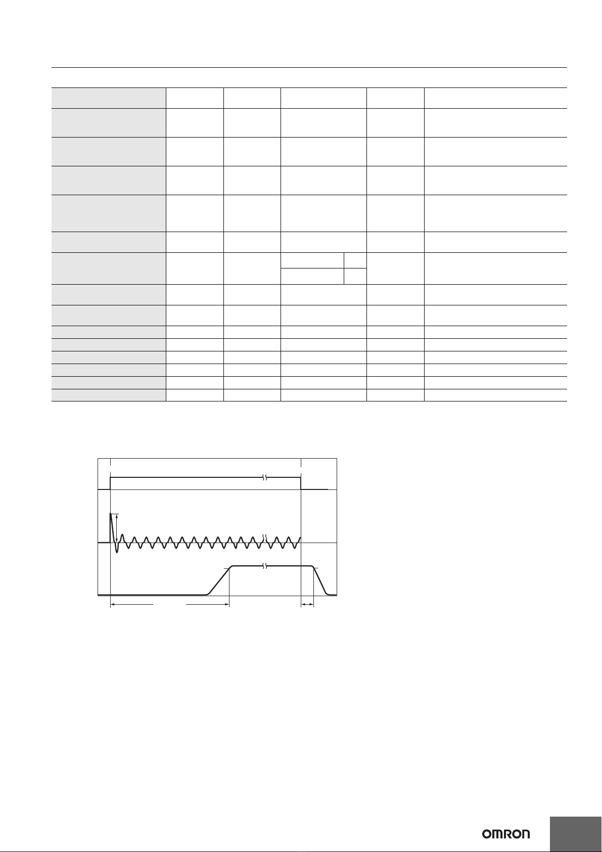
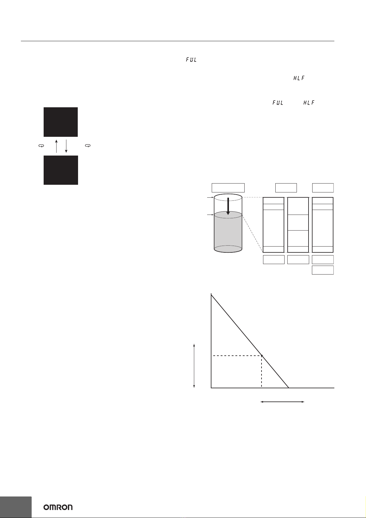
Inrush current Values for a cold start at 25°C.
Refer to Inrush Current, Startup Time, and Output Hold Time on page 7 for details.
Output
characteristics
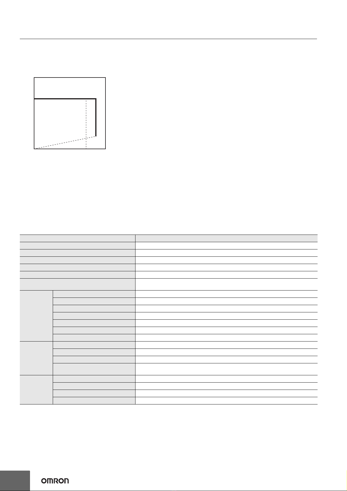
Voltage adjustment range
If the output voltage adjuster (V. ADJ) is turned, the voltage will increase by more than of the voltage adjustment
range.
When adjusting the output voltage, confirm the actual output voltage from the product and be sure that the load is
not damaged.
Ripple noise voltage The value is when both rated output voltage and rated output current are satisfied.
A characteristic when the ambient operating temperature is 25°C.
Static input variation
influence
This is the maximum variation in the output voltage when the input voltage is gradually changed within the allowable
input voltage range at the rated output voltage and rated output current.
Load variation influence 100 to 240 VAC input, in the range of 0 A to the rated output current.
Startup time
The value is when both rated output voltage and rated output current are satisfied and at room temperature (25°C).
Refer to Inrush Current, Startup Time, and Output Hold Time on page 7 for details.
Hold time
The value is when both rated output voltage and rated output current are satisfied and at room temperature (25°C).
Refer to Inrush Current, Startup Time, and Output Hold Time on page 7 for details.
Environment Ambient operating
temperature
At -40 to -25°C, time will be required before the rated output voltage is output after the input voltage is input. Also,
the ripple noise value may exceed the value shown in the above table.
Reliability MTBF
MTBF is calculated according to JEITA RCR-9102.
MTBF stands for Mean Time Between Failures, which is calculated according to the probability of accidental device
failures, and indicates reliability of devices.
Therefore, it does not necessarily represent a life of the product.
Life expectancy
Refer to Recommended Replacement Periods and Periodic Replacement for Preventive Maintenance on page 27 for details.