Simplicity DTA6SY2B User manual


1
2
3
min 650 mm
A
FB
C
F
E
H
90°
335
205
600 / 900
G

o 150
4
a
b
5
K
C
B
M

7
250
95
349
420
600 / 900
270
min 580
150
8
max 1050
6
0
AAL
1
2
3
3L
2L
1L
L

EN 1
OPERATION AND MAINTENANCE
MANUAL
Dear customer,
You have purchased a product of our new series of
cooker hoods. We hope that our product will serve
you well and for long time. We recommend you to
study these instructions and to operate this product
according to them.
IMPORTANT INFORMATION AND
RECOMMENDATIONS
The cooker hood should not be connected to
smoke flue, which is used for combustion exhaust
The appliance can be used in exhaust mode (the
exhaustion of exhalations into waste air stack) or,
after additional buying of carbon filter and
recirculation set in recirculation mode (circulation
through carbon filter).
If there is in operation simultaneously with the
cooker hood (in exhaustion mode) appliance of
type B in the same room - heat source (for
instance with gas, oil, diesel fuel or with solid
fuel), which draw combustion air directly from the
room, then it should be taken into account, that
these appliances create at combustion a certain
level of under-pressure. Therefore it is necessary
to provide a sufficient inflow of air (from the
outside environment).
Do not handle with open flame under the cooker
hood (for instance at flambéing etc.)!
The big fat deposits from roasting on the grease
filter should be regularly removed.
Follow the below determined instructions at
replacing of filters.
This appliance should be operated with adults
only.
This appliance is designed for normal household
use.
This appliance is not designed for use with
persons (including children), their physical,
sensual or mental disability or lack of experience
and knowledge hinders the safe use of appliance,
except when they are under supervision or they
were introduced concerning use of appliance with
the person responsible for their safety. The
children should be supervised for ensure, that
they would not play with the appliance.
The accessible parts could be hot at using of
cooking devices.
The cooker hood is an electric appliance with Y –
type connection. If the power cord is damaged, it
should be replaced with the producer, his/her
service technician or with similarly qualified
person, for to prevent the creation of dangerous
situation.
The producer is not responsible for damages
caused with faulty installation or faulty using of
appliance.
ATTENTION
Plug in cooker hood to the net before fixing on the
wall and check function of motor (all speeds) and
function of lights.
Check whether motor is not too noisy, whether
have regular running.
Do not remove protection foil from cooker hood
and decoration chimney.
Check if carton box is not demaged, check
sufrace of cooker hood if there are not scratches
or dishing.
IN CASE OF FAILS DO NOT FIX COOKER
HOOD ON THE WALL AND CLAIMED IT AT
YOUR SALER!!!
Fix the cooker hood on the wall with protection
foil. After fixing and setting right height
of decoration chimney remove protection foil.
Do not move with decoration chimney without
protection foil. In other case there will be
scratches on surface.
Following these instructions you avoid useless
claiming.
DESCRIPTION (FIG.1)
A - Cooker hood
B - Lower part of decoration chimney
C - Upper part of decoration chimney
E - Carbon filter (for recirculation only)
F - Grease filter –metal cassette
M - Cover of decorative chimney
H - Switch
ELECTRIC CONNECTION
Check before installation of appliance that the
voltage in your power net corresponds to data
given on the production sheet inside of the
appliance.
The appliance is provided with a power cord is
ended with a plug –class I. of protection against
electric shock.
Connect the appliance to a socket corresponding
to valid national standards.
INSTALLATION
The distance between the cooker hood and the
hotplate should not be less as 650mm (fig.2).
ATTENTION
The attached dowels and screws are designed for
fastening of cooker hood on a wall from concrete
or full bricks. For other wall material a
corresponding type and size of dowels and
screws should be used.
Leave the fastening of cooker hood to a
specialist!

EN 2
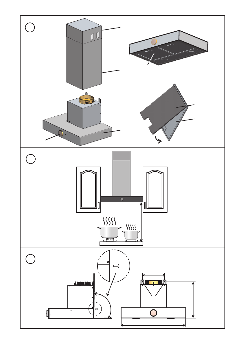
MOUNTING OF COOKER HOOD
Unpack the appliance from packaging.
Drill holes for fasteners according the drawing 3.
Tap the fasteners to drilled holes.
Fix the appliance with provided screws throu
holes “G”
IMPORTANT
The horizontal location of cooker hood should
be observed.
THE EXHAUSTION VERSION
At use of exhaustion version (see fig. 4) the
exhalations are led into the exhaustion opening
with the exhaustion hose, which is connected to
the cooker hood with a flange. The exhaustion
hose and the fastening clips should be bought
additionally.
The exhaustion is provided through the upper
outlet of the cooker hood, on which the
exhaustion hose should be connected and the
other end of hose should be connected into the
exhaustion opening. The diameter of exhaustion
hose should be the same as the diameter of
connecting flange –e.g. Ø150mm, or Ø 120mm
with a reduction piece (if you use connection hose
Ø 120mm, you will decrease exhaust capacity
and increase noise level).
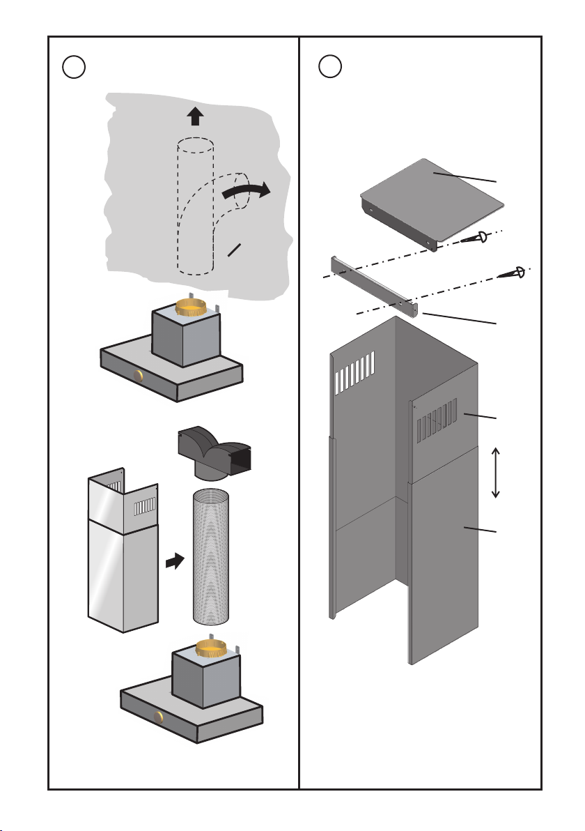
MOUNTING OF EXHAUSTION VERSION
AND OF DECORATION CHIMNEY
Fasten with help of a hose clip on the hinged on
cooker hood the one end of exhaustion hose,
fasten the other end into the exhaustion opening.
Both parts (the upper C and lower B) of
decoration chimney, shifted one to the other,
place on the hinged on cooker hood.
Shift the upper part C into the required height,
mark the upper location and mark the fastening
openings of console (K).
Remove the decoration chimney and bore the
marked openings for the dowels.
Screw on the console (K) together with cover of
decoration chimney (M).
Fasten once more the both parts of decoration
chimney, shift out its upper part and fasten to the
console with two screws.
IMPORTANT
Remove protection foil from decoration chimney
not untill last assembly of decoration chimney!
IMPORTANT!
The carbon filter should not be installed in the
cooker hood at exhaustion version.
RECIRCULATION VERSION
A carbon filter and recirculation set should be
bought for the cooker hood in recirculation
version (fig. 9). The exhalations are exhausted
through the carbon filter.(fig. 1 (E)) The circulation
air with removed smell is led with exhausted hose
through air spreader to the ventilation openings in
upper part of decorative chimney to the room.
This version is used in cases, when there is no
waste air stack at disposal.
It is necessary to count with a longer reaction time
at recirculation in automatic regime.
CAUTION!
The carbon filter should be installed in the
cooker hood at recirculation.
SETTING UP OF CAPACITY LEVEL FOR
THE COOKER HOOD
The cooker hood can work in two regimes:
Manual
Automatic
SETTING UP OF COOKER HOOD
CAPACITY LEVEL IN MANUAL MODE
Power level 1, 2, 3 is set by turning the control
knob.
If the control knob is set on 1L, 2L, 3L ventilation
and light is powered together.
SETTING UP OF COOKER HOOD
CAPACITY LEVEL IN AUTOMATIC MODE
The automatic regime can be switched on with
setting of switch button to position „A“ or „AL“. The
cooker hood is running on the capacity level 1 during
60 seconds, the sensor is heated up during this
period. The sensor is ready for operation after
heating up. The sensor thereafter measures
continuously the pollution level of air and according
to the measured value regulates the capacity levels
between 0 and 3.
TURNING ON THE LIGHTS
Light is ON when the control knob is in position “L”.
TURNING OFF THE HOOD
The hood is OFF when the control knob is in position
“0”.
THE COOKER HOOD IS EQUIPPED WITH
THE SAFETY SWITCHING OFF FUNCTION
When the switch button is in a position different to
„A“ or „AL“ and this setting will be not changed
during a period of one week, then the electronic
control of hood will be switched off automatically.
The cooker hood is then in a condition
corresponding to switch button position 0.
REMARK
The cooker hood electronics regulates the capacity
levels corresponding to gas and vapor concentration
level measured with the sensor. This regulation can
differ from expectations derived from visual
monitoring of vapor occurrence.
At recirculation mode the air in the room is not
exchanged, so the humidity and pollution of air is not

EN 3
decreased. So the cooker hood in automatic regime
and in extreme cases can constantly measure a
higher level of air pollution and the hood will be not
switched off. The best use of this function can be
achieved with selecting the automatic regime at the
beginning of cooking and with it switching off after
finishing of cooking.
MAINTENANCE AND CLEANING
At cleaning or maintenance switch the appliance
off from the power and this with disconnecting
from the socket or with switching off of
corresponding circuit breaker.
The regular maintenance and cleaning ensure the
efficiency, reliability and longer lifetime of cooker
hood.
Pay special attention to grease filter and to
carbon filter.
For cleaning of cooker hood do not use cleaning
articles containing aggressive substances mainly
chlorine and dissolvents.
GREASE METAL FILTER
The grease metal filter (F) catches the fat
particles.
The metal filter should be cleaned manually or in
dishwasher (at 65C) with use of appropriate
detergents.
The filter can slightly change its color when
washed in dishwasher; nevertheless this fact has
no influence to its functionality.
Let the filter thoroughly dry after washing and
return it to cooker hood in dry state only.
CASSETTE CARBON FILTER
The carbon filter (E) absorbs the kitchen smell.
The carbon filter should be never washed!
INSTALLATION OF CASSETTE CARBON
FILTER
Disconnect the appliance from the power net.
Take out the grease filter (F) and fasten the
cassette carbon filter (E) to its internal side –see
the picture.
NOTICE!
The caught fat in the filter has influence not only to
the effectiveness of cooker hood but at neglected
maintenance could cause also a fire! Therefore we
recommend the observation of instructions for
cleaning and changing of filters.
LIQUIDATION OF CARBON FILTERS
AFTER FINISHED LIFETIME
The used filters can be put to normal household
waste.
The liquidation should be provided in
concordance with the corresponding national
standards and regulations.
LIGHTING
The cooker hood has halogen bulbs 2 x 20 W
(type 12V/20W - G4).
REPLACING OF HALOGEN BULB (FIG. 7)
Disconnect the cooker hood from the power net.
Shift a flat piece (a small screwdriver or flat knife)
carefully between the rings of halogen lighting.
With slight lever action make free the internal ring
with the glass cover of lighting.
Provide the replacement of halogen bulb.
Return back the ring with the glass cover of
lighting to original location.
CAUTION!
Do not touch the halogen bulbs with your naked
fingers
CLEANING
Clean regularly the internal and external parts of
cooker hood with soft cleaning agents.
Never use abrasive cleaning means.
Clean the glass surfaces with special means for
glass, mirrors and windows.
METHOD OF USE AND LIQUIDATION OF
PACKAGING
Grooved cardboard, packaging paper
- sale to waste collecting company
- to collecting vessels for used paper
- other reuse
Polystyrene
- to corresponding collecting vessels
Packaging foil and PE backs
- to collecting vessels for plastic
LIQUIDATION OF APPLIANCE AFTER
FINISHING OF USE
This appliance is marked in accordance with
Directive 2012/19/EU on manipulation with waste
from electric and electronic equipment –WEEE.
This directive determines the unified European (EU)
frame for collection and recycling of used
equipment.
The appliance contains valuable materials which
should be reused after finishing of their use. Please
give your used appliance to waste processing
company.
CLAIMS
If there is any defect on the appliance within the
guarantee period, do not repair itself. Apply a claim
in the shop in which you bought the appliance or at
service representatives, mentioned in the Guarantee
conditions.

EN 4
At applying of claim observe the text of Guarantee
sheet and Guarantee conditions.
REMARK
The producer reserves the right for providing of
minor changes, resulting from innovations or from
technologic modifications of the product.
BASIC TECHNICAL DATA
Type
DTA6SY2B
DTA6SY2W
Quantity of motors
1
Max. motor capacity
200W
Lighting - halogen
2 x 20W
Total power consumption of
cooker hood
240W
Electric voltage
230V ~
Protection class against
electric shock
I.
Dimensions (mm):
w x d x h (Fig. 8)
600 x 420 x 352
Noise level
66 dBA
Color –version
Inox –glass
Grease filter
2 pc –metal
Control
SWITCH
Number of capacity levels
3
Exhaustion
Exhaustion with reduction
150mm
120mm
Exhaustion
- UPPER
-RECIRCULATION
ACCESSORIES OF COOKER HOOD
Dowels and screws for mounting of cooker hood on
a wall and screws for fastening of decoration
chimney
Screws 5 x 50mm (4 pieces)
Screw 3,9 x 8mm (2pc)
Dowels H 8 (4 pieces)
Upper cover of decoration chimney for recirculation
Console for fastening of decoration chimney
Decoration chimney (2 pieces)
Backflow valve –is integral part of ventilator motor
Reduction 150 / 120mm
BASIC TECHNICAL DATA
Type
DTA9SY2B
DTA9SY2W
Quantity of motors
1
Max. motor capacity
200W
Lighting - halogen
2 x 20W
Total power consumption of
cooker hood
240W
Electric voltage
230V ~
Protection class against
electric shock
I.
Dimensions (mm):
w x d x h (Fig. 8)
900 x 420 x 352
Noise level
66 dBA
Color –version
Inox –glass
Grease filter
3 pc –metal
Control
SWITCH
Number of capacity levels
3
Exhaustion
Exhaustion with reduction
150mm
120mm
Exhaustion
- UPPER
-RECIRCULATION
*The declared noise emission level of this appliance
is 66 dB(A), what represents the A level of acoustic
power in comparison to reference acoustic power
1pW.
ACCESSORIES OF COOKER HOOD FOR
ORDERING
Carbon filter –set - SAP 428642
Exhaustion hose
120 or150 mm + fastening clip
Recirculation set - SAP 431926
447062en

FICHE
Symbol
Unit
Value
Value
Supplier’s name or trade mark
GORENJE
GORENJE
Model identification
DTA6SY2B
DTA6SY2W
DTA9SY2B
DTA9SY2W
Annual energy consumption
AEChood
kWh/annum
143,8
141,3
Energy Efficiency class
E
E
Fluid dynamic efficiency
FDEhood
%
15,3
16
Fluid Dynamic Efficiency class
D
D
Lighting efficiency
LEhood
Lux/W
13,6
8,7
Lighting Efficiency class
D
E
Grease filtering efficiency
GFEhood
%
85
85
Grease Filtering Efficiency class
C
C
Air flow - at minimum speed in
normal use
m3/h
201
198
Air flow - at maximum speed in
normal use
m3/h
618
630
Air flow - at intensive or boost
setting
m3/h
-
-
Sound power, at minimum speed
available in normal use
A
dB
46
46
Sound power, at maximum speed
available in normal use
A
dB
66
66
Sound power, at intensive or
boost setting
A
dB
-
-
Measured power consumption off
mode
Po
W
0,36
0,36
Measured power consumption in
standby mode
Ps
W
3,9
3,9
Time increase factor
f
1,5
1,4
Energy efficiency index
EEIhood
%
104,1
102,8
Measured air flow rate at best
efficiency point
QBEP
m3/h
346
350
Measured air pressure at best
efficiency point
PBEP
Pa
291
300
Maximum air flow
Qmax
m3/h
617
630
Measured electric power input at
best efficiency point
WBEP
W
183
182
Nominal power of the lighting
system
WL
W
40
40
Average illumination of the
lighting system on the cooking
surface
Emiddle
Lux
545
347
Sound power level
LWA
dB
66
66
en

Other manuals for DTA6SY2B
1
This manual suits for next models
3
Table of contents
Other Simplicity Ventilation Hood manuals
Popular Ventilation Hood manuals by other brands

Electrolux
Electrolux EFB70550BX user manual

Ancona
Ancona GLC636 User's manual & installation instructions

FALMEC
FALMEC Zeus Pro Instruction booklet

Maico
Maico ER-A Installation and operating instructions

Siemens
Siemens LI97SA531 User manual and assembly instructions

Faber
Faber Ostro 30 SS 400 cfm Installation instructions; use and care information