SimpliPhi Power Sol-Ark-8K Quick setup guide


SimpliPhi Power, Inc. |3100 Camino Del Sol |Oxnard, CA 93030, USA |(805) 640-6700 | info@simpliphipower.com |SimpliPhiPower.com
|
2
|
REV202008141736
© SIMPLIPHI POWER
SimpliPhi Your Energy Security
and Independence
and gain control of your own power.
SimpliPhi Power helps you manage your power as a personal resource. Anytime.
Anywhere. SimpliPhi energy storage optimizes integration of any power
generation source – solar, wind, generator – on or off grid, and protects your
home and mission-critical business functions from power outages and
intermittency. SimpliPhi storage technology reduces operating temperature
constraints, the risk of thermal runaway and eliminates toxic coolants. Safe
lithium ferrous phosphate (LFP). No cobalt. No toxic hazards.
SimpliPhi’s battery technology utilizes the industry’s most environmentally
benign chemistry (LFP) combined with proprietary architecture and power
electronics (BMS) to create a portfolio of high performance, scalable and
enduring energy storage solutions that provide power security, resilience and
daily cycling for savings on your utility bill – all with a 98% efficiency rate.
SimpliPhi Power offers proprietary, commercially availableenergy storage and management systems that are
safe, non-toxic, reliable, durable, efficient, highly scalable, and economical over the lifetime of the PHI Battery.

SimpliPhi Power, Inc. |3100 Camino Del Sol |Oxnard, CA 93030, USA |(805) 640-6700 | info@simpliphipower.com |SimpliPhiPower.com
|
3
|
REV202008141736
© SIMPLIPHI POWER
Table of Contents
1.0 – Introduction.......................................................................................................................... 4
2.0 – Battery Bank-to-Inverter Connection ................................................................................ 4
3.0 – Battery Bank Sizing .............................................................................................................. 7
3.1 – All Systems ...................................................................................................................................... 7
4.0 – Program Settings for PHI Batteries .................................................................................... 9
4.1 – Depth of Discharge ........................................................................................................................ 9
4.2 – Inverter and Charger Settings ....................................................................................................... 9
4.3 – Grid Setup ..................................................................................................................................... 14
5.0 – Use Cases & Application Notes......................................................................................... 16
5.1 – AC Coupled................................................................................................................................... 17
5.2 – Grid Sell / Grid-Tied with Battery Backup .................................................................................. 17
5.3 – Limited to Home ........................................................................................................................... 18
5.4 – Limited to Load ............................................................................................................................. 18
5.5 – Time of Use Selling / Energy Arbitrage ....................................................................................... 19
5.6 – Off-Grid......................................................................................................................................... 20
5.7 – Generators.................................................................................................................................... 20
5.6 – Smart Load .................................................................................................................................... 21
6.0 – Specifications & Warranty................................................................................................. 22
7.0 – SimpliPhi Power Technical Support .................................................................................. 22
SimpliPhi Power, Inc. |3100 Camino Del Sol |Oxnard, CA 93030, USA |(805) 640-6700 | info@simpliphipower.com |SimpliPhiPower.com
|
4
|
REV202008141736
© SIMPLIPHI POWER
1.0 –Introduction
This integration guide covers the recommended set up and configuration of Sol-Ark equipment for optimizing
performance with SimpliPhi’s AmpliPHI batteries.
CAUTION: THIS INTEGRATION GUIDE IS RELEVANT TO AMPLIPHI BATTERIES ONLY.
REFER TO THE SOL-ARK INTEGRATION GUIDE FOR SIMPLIPHI POWER PHI BATTERIES,
LINKED HERE, FOR APPLICATIONS USING CORE POWER PHI BATTERIES THAT DO
NOT INCLUDE A NETWORKING COMMUNICATIONS PORT.
More information on SimpliPhi products can be found on our website at https://simpliphipower.com/. All
SimpliPhi Product Documentation can be found at https://simpliphipower.com/product-documentation/. More
information regarding Sol-Ark’s products can be found at https://www.sol-ark.com.
The Sol-Ark products covered in this guide are the Sol-Ark-8K and the Sol-Ark-12K-P. Limiter sensors
referenced in this Guide are included with a purchase of Sol-Ark equipment. Sol-Ark equipment includes a built-
in transfer switch but not a critical loads panel.
Contact SimpliPhi Power Technical Support (805-640-6700; techsupport@simpliphipower.com) regarding any
compatibility questions for products not listed in this guide.
2.0 –Battery Bank-to-Inverter Connection
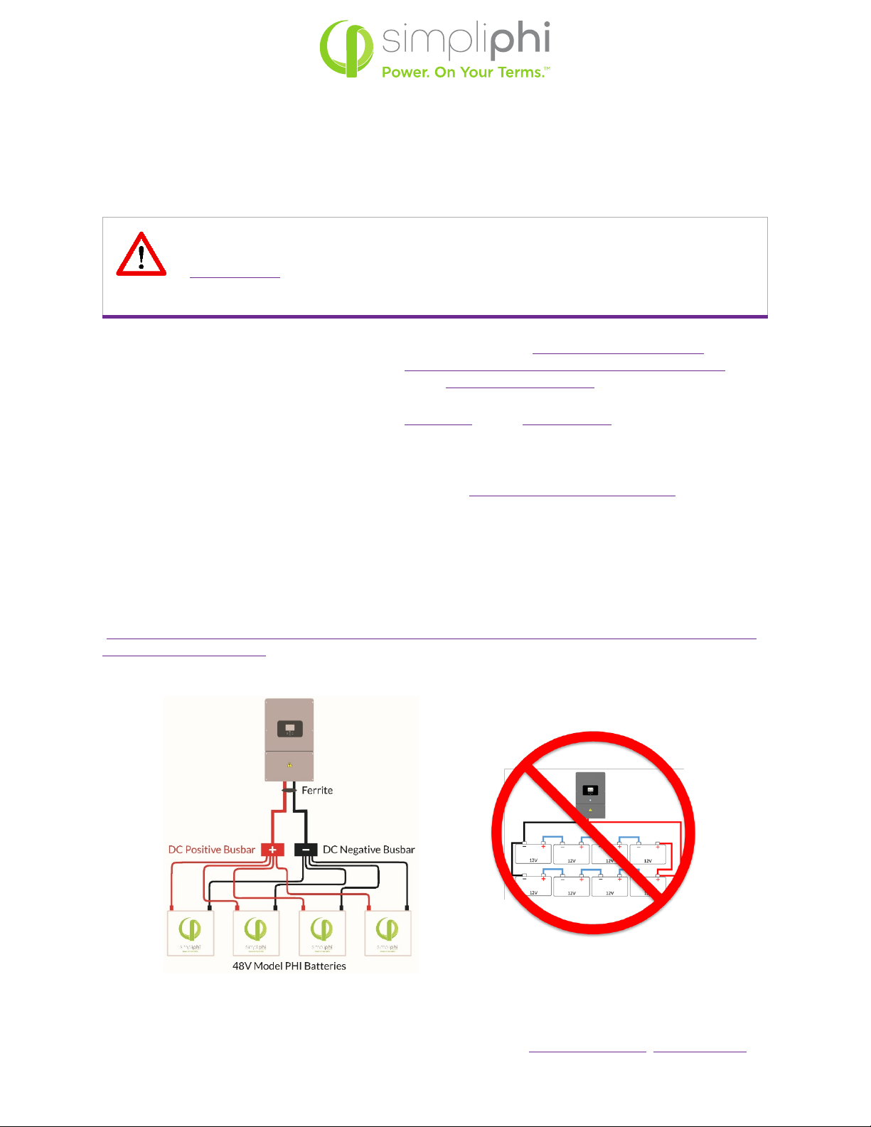
Wire the AmpliPHI Battery bank to the Sol-Ark according to the AmpliPHI Battery Installation Manual
[https://simpliphipower.com/wp-content/uploads/documentation/ampliphi-series/simpliphi-power-ampliphi-
3-8-installation-manual.pdf], not according to the Sol-Ark Manual:
Figure 1: Solar-Ark to Battery Connection

SimpliPhi Power, Inc. |3100 Camino Del Sol |Oxnard, CA 93030, USA |(805) 640-6700 | info@simpliphipower.com |SimpliPhiPower.com
|
5
|
REV202008141736
© SIMPLIPHI POWER
It is acceptable but not required to use the ferrite choke on the positive and negative DC busbar-to-inverter
leads (see Figure 1 above).
SimpliPhi and Sol-Ark recommend against using the 100 Ohm resistor included with the Sol-Ark equipment to
charge the Sol-Ark’s capacitors when connecting the SimpliPhi Batteries for the first time (as described in the
Sol-Ark Install Guide Owner’s Manual).
Do not install the Battery Temperature Sensor. The SimpliPhi Batteries require no temperature compensation.
AmpliPHI batteries are networked together in a daisy chain using CAT5 or greater cabling and utilizing the two
battery ports that that are in closer proximity to each other (identified in Figure 2 below). The maximum
number of AmpliPHI batteries that can be connected in a single system is 30, with a maximum total connected
distance of 40m (131 feet) from the first AmpliPHI battery module to the last AmpliPHI battery module in the
chain.
Figure 2: AmpliPHI’s Networking Communications Ports
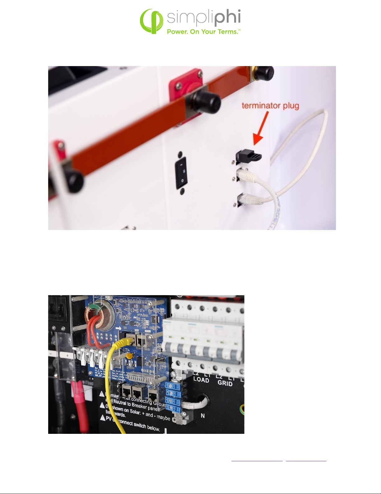
In a string of batteries, the two batteries at the ends of the communication chain will have one of their RJ45
“daisy-chaining” ports (indicated in Figure 2 above) remaining un-utilized. On each of these two batteries, the
communication port that is not occupied by a cable will have a 120Ohm terminator plug installed in the open
port (see Figures 3 and 5 below).
RJ45 ports used for daisy chaining networking
connections between AmpliPHI batteries
SimpliPhi Power, Inc. |3100 Camino Del Sol |Oxnard, CA 93030, USA |(805) 640-6700 | info@simpliphipower.com |SimpliPhiPower.com
|
6
|
REV202008141736
© SIMPLIPHI POWER
Figure 3: AmpliPHI’s Terminator Plug
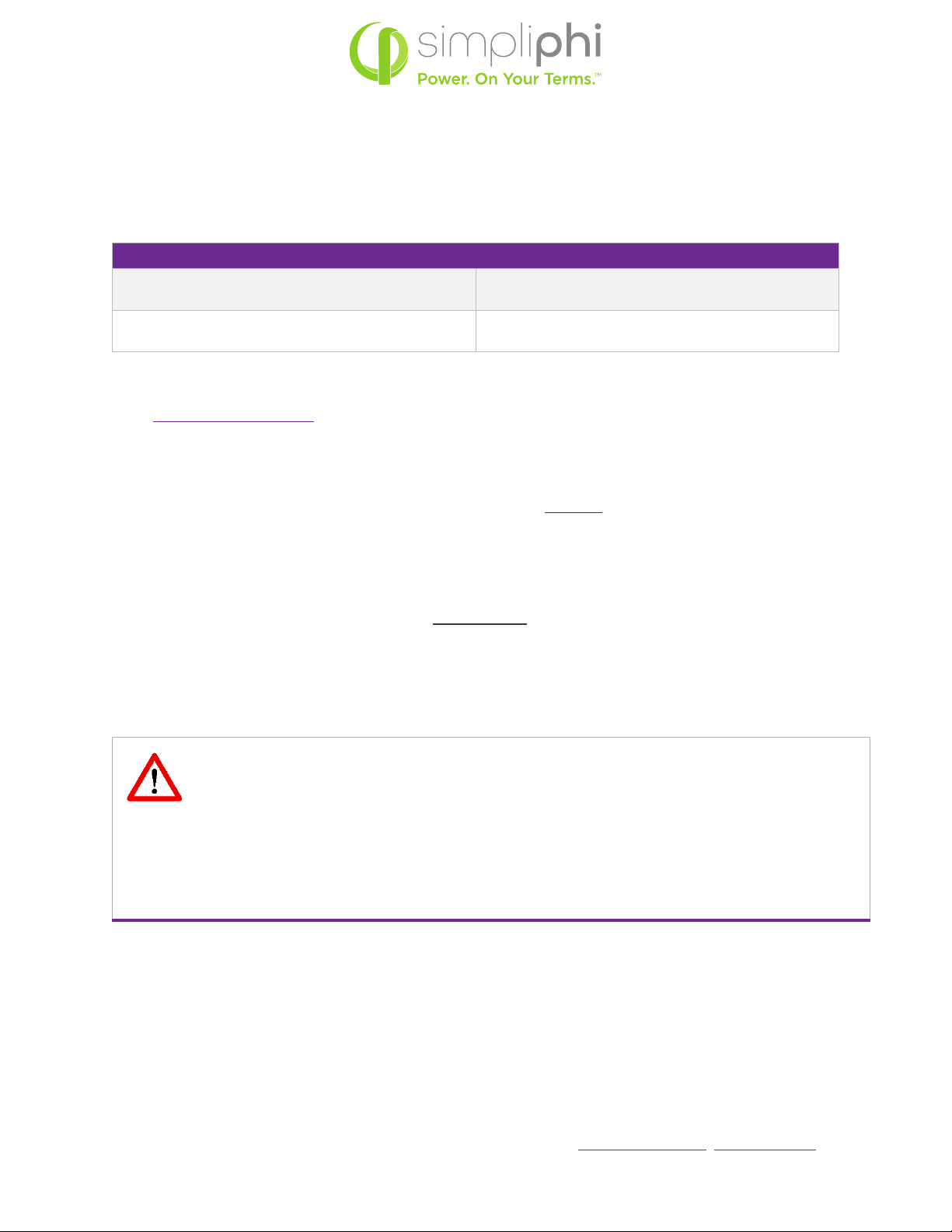
Utilizing the closest battery to the inverter, create the closed loop communications bridge between the
AmpliPHI Battery and the Communication Input Port (labeled “CAN”) in the Sol-Ark Inverter utilizing CAT5 or
greater cable. The cable length from the last AmpliPHI Battery in the chain to the Inverter cannot exceed 40m
(131 feet).
Figure 4: Sol-Ark’s Battery Networking Connection Port

SimpliPhi Power, Inc. |3100 Camino Del Sol |Oxnard, CA 93030, USA |(805) 640-6700 | info@simpliphipower.com |SimpliPhiPower.com
|
7
|
REV202008141736
© SIMPLIPHI POWER
Figure 5: AmpliPHI’s Networking Connections to Sol-Ark Equipment
3.0 –Battery Bank Sizing
3.1 – All Systems
AmpliPHI batteries in DC Coupled or AC Coupled systems should be sized according to the connected loads’
energy (kWh) and power (kW) requirements. While as few as one AmpliPHI battery may be paired with either
Sol-Ark-8K or Sol-Ark-12K equipment without voiding the battery warranty, consider that the AmpliPHI
battery is rated according to the specifications in the table below, and that without a backup AC power source,
loads that exceed the battery bank’s total capacity or power rating will result in the entire system shutting
down. Specifically, when operating in off-grid mode, the Sol-Ark shuts down when the current discharged from
the battery bank to the loads exceeds 120% of the Sol-Ark’s Max A Discharge parameter value for 10 seconds.
Battery bank-to-inverter
networking connection
Terminator plugs at
either end of the
battery “daisy-chain”
bank-to-inverter
networking connection
SimpliPhi Power, Inc. |3100 Camino Del Sol |Oxnard, CA 93030, USA |(805) 640-6700 | info@simpliphipower.com |SimpliPhiPower.com
|
8
|
REV202008141736
© SIMPLIPHI POWER
For example, one AmpliPHI battery has a maximum continuous discharge rate of 37.5 Amps DC. The AmpliPHI
battery communicates this value to the Sol-Ark and auto-populates the Sol-Ark’s Max A Discharge parameter
to this value. When 45 Amps DC (120% of 37.5 ADC) are discharged from the battery to the loads (equivalent
to a ~9 Amps at 240 VAC load), then the system will shut down.
AmpliPHI 3.8 Battery
Rated kWh Capacity per Battery
3.8 kWh DC @ 100% DoD
3.04 kWh DC @ 80% DoD (recommended)
MAX Continuous Discharge Rate
37.5 Amps DC (1.9 kW DC)
*Multiply by the number of AmpliPHI batteries in the battery bank for total capacity and power ratings.
Note: In a DC Coupled system, the AmpliPHI battery’s maximum charge rate (37.5 Amps DC, or 1.9 kW DC)
need not be considered when sizing the AmpliPHI battery bank. DC coupled photovoltaic (PV) connected
via the Sol-Ark’s charge controllers will limit charging current based on the Sol-Ark’s Max A Charge setting
without issue.
Charge Example: # ≥
.×
•AC Coupled Solar PV Array is rated at 8 kW
•PHI 3.8 kWh-51.2Vnom battery has a maximum continuous charge rate of 1.92 kWDC
# ≥
.×.
=.
A properly sized PHI battery bank based on the maximum charge from the AC Coupled solar PV array has a
minimum of 6 batteries. This helps ensure that the battery bank receives as much charge as possible from the
AC Coupled solar PV.
CAUTION: USING FEWER THAN THE CALCULATED NUMBER OF PHI BATTERIES IN THIS
AC COUPLED CHARGE CALCULATION MAY RESULT IN LIMITEDLY EFFECTIVE CHARGING
FROM AC COUPLED PV IN OFF-GRID OR GRID-OUTAGE CONDITIONS. WHEN THE
OUTPUT OF THE AC COUPLED SOLAR PV ARRAY EXCEEDS THE MAX A CHARGE
PARAMETER, AND FREQUENCY SHIFT IS UNABLE TO MITIGATE THE OUTPUT, THE
BATTERY CHARGING WILL BE INTERRUPTED. TO AVOID THIS, PV ARRAY SIZING NEEDS
TO BE ADJUSTED TO ACCOMMODATE THE MAX A CHARGE PARAMETER FOR THE
OVERALL SYSTEM.

SimpliPhi Power, Inc. |3100 Camino Del Sol |Oxnard, CA 93030, USA |(805) 640-6700 | info@simpliphipower.com |SimpliPhiPower.com
|
9
|
REV202008141736
© SIMPLIPHI POWER
Homeowners with little to no loads on during the day (while solar power production is at its peak) might
consider sizing a larger PHI battery bank to take advantage of the entire solar PV output potential for battery
charging. Homeowners that consistently power loads during peak solar power production times may require a
smaller sized battery bank.
4.0 –Program Settings for PHI Batteries
The AmpliPHI battery is capable of automatically communicating many of the battery’s operating parameters
to the Sol-Ark equipment. Parameters that must be manually programmed into the Sol-Ark are in red in Table 1
on page 12.
4.1 – Depth of Discharge
To optimize the PHI batteries’ and overall system’s performance and life, SimpliPhi Power highly recommends
programming the equipment settings for an 80% maximum Depth of Discharge (DoD). Maintaining the PHI
battery at this DoD ensures the greatest level of SimpliPhi battery health. This affects the “Start %” parameter
in the Charge menu and the “Shutdown”, “Low Batt”, and “Restart” parameters in the Discharge menu, marked
in red in Table 1 on page 12.
CAUTION: IF A FIRMWARE UPDATE IS EXECUTED ON THE SOL-ARK EQUIPMENT, ALL
THE SETTINGS MUST BE REVERIFIED. THE PROGRAMMED SETTINGS SHOWN IN THE
FOLLOWING TABLES MUST BE APPLIED BASED ON DESIRED WARRANTY/CYCLE LIFE.
THE RECOMMENDED IS 80% DEPTH OF DISCHARGE.
4.2 – Inverter and Charger Settings
Refer to Sol-Ark’s Menus and Programming online video
(https://www.youtube.com/watch?v=mcXXzgfRT90&t=1497s) for guidance on programming the settings
outlined in Table 1 below.
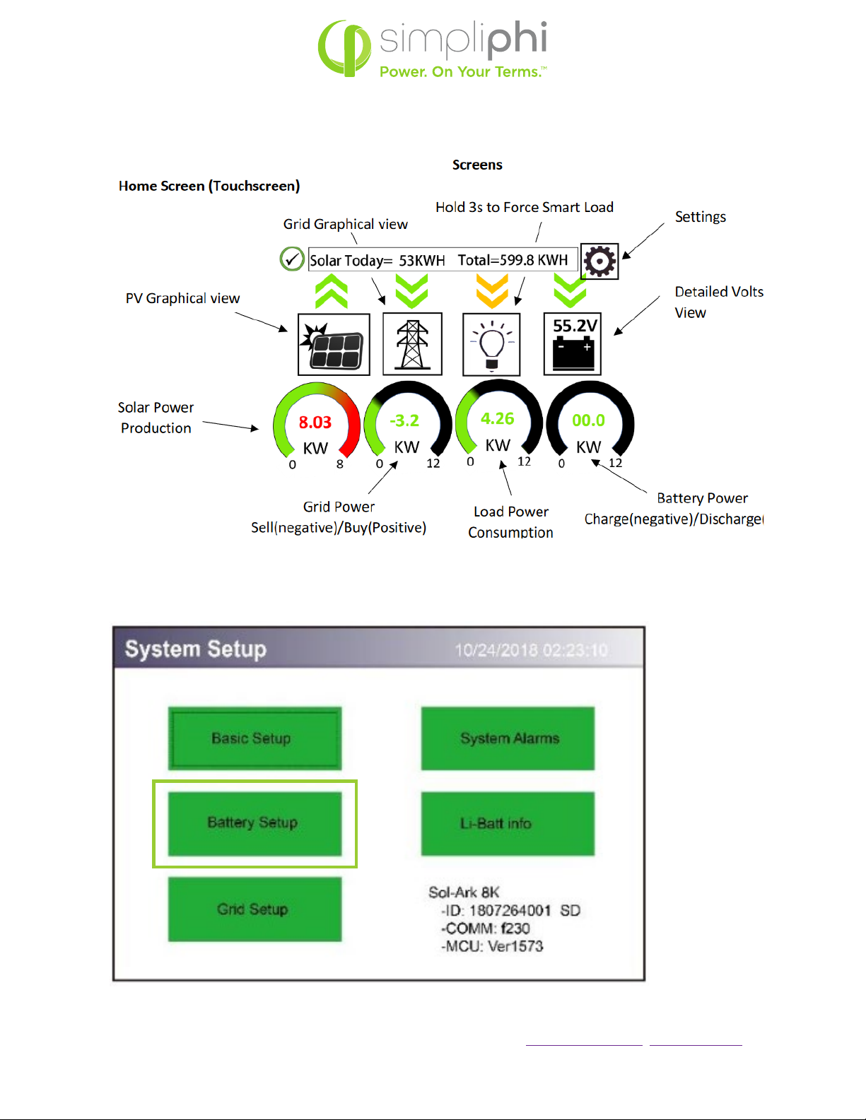
Press the gear icon to get to the Settings menu (Figure 6), then press Battery Setup (Figure 7) to program the
parameters in Figure 6 and 7 below.
SimpliPhi Power, Inc. |3100 Camino Del Sol |Oxnard, CA 93030, USA |(805) 640-6700 | info@simpliphipower.com |SimpliPhiPower.com
|
10
|
REV202008141736
© SIMPLIPHI POWER
Figure 6: Sol-Ark Home Screen (Touchscreen), from the Sol-Ark Installation Manual
Figure 7: Sol-Ark System Setup Screen, from the Sol-Ark Installation Manual
SimpliPhi Power, Inc. |3100 Camino Del Sol |Oxnard, CA 93030, USA |(805) 640-6700 | info@simpliphipower.com |SimpliPhiPower.com
|
11
|
REV202008141736
© SIMPLIPHI POWER
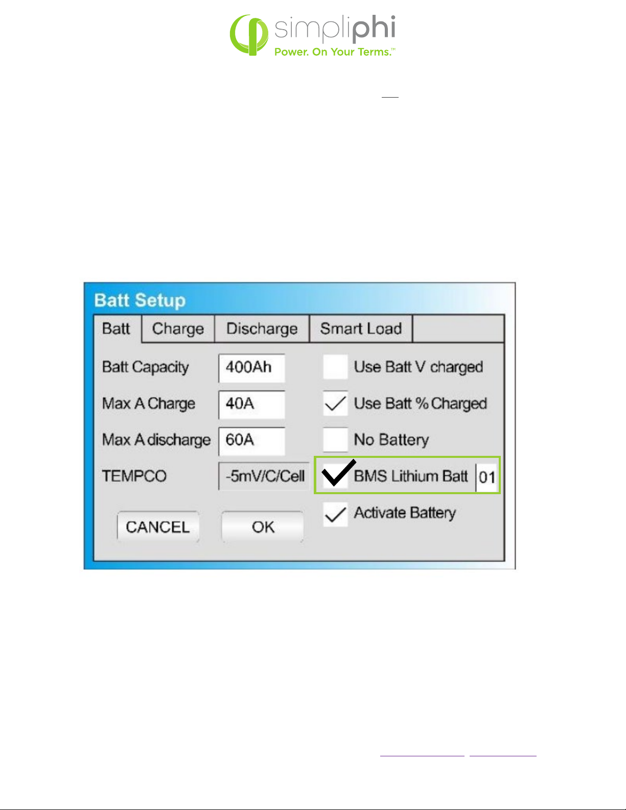
Checking the BMS Lithium Batt box in the Batt Setup menu’s “Batt” tab first will auto-populate all values
communicated from the AmpliPHI batteries to the Sol-Ark (see Figure 8 below). These auto-populated
parameters will include:
•Batt Capacity (Battery Setup Batt menu)
•Max A Charge (Battery Setup Batt menu)
•Max A Discharge (Battery Setup Batt menu)
•TEMPCO (Battery Setup Batt menu)
•A (referring to Gen/Grid Charge Amps in the Battery Setup Charge menu)
•Float V (Battery Setup Charge menu)
•Absorption V (Battery Setup Charge menu)
•Equalization V / days / hours (Battery Setup Charge menu)
Figure 8: BMS Lithium Batt Box to be Checked First
SimpliPhi Power, Inc. |3100 Camino Del Sol |Oxnard, CA 93030, USA |(805) 640-6700 | info@simpliphipower.com |SimpliPhiPower.com
|
12
|
REV202008141736
© SIMPLIPHI POWER
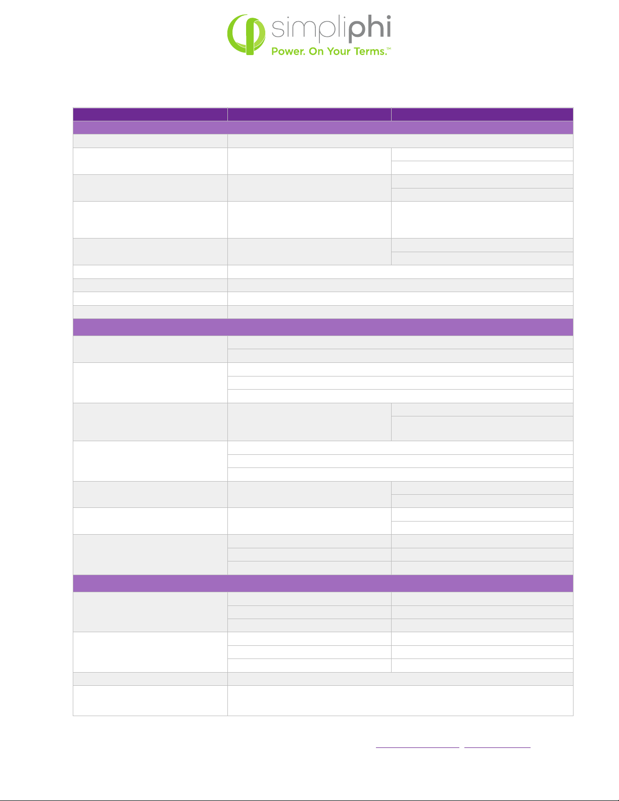
Table 1 – Sol-Ark Battery Settings for AmpliPHI Battery Models
System Setup > Battery Setup
for your reference
AmpliPHI
> Batt Tab
BMS Lithium Batt Manually check this box
Batt Capacity 75 Ah per AmpliPHI 3.8 battery BMS handles SOC determination.
No manual programming needed
Max A Charge1,2 ≤37.5 ADC per PHI 3.8 battery (Lower
charge rates improve battery life)
BMS auto-populates Max A Charge.
No manual programming needed.
Max A Discharge1≤37.5 ADC per PHI 3.8 battery BMS auto-populates Max A Discharge. No
manual programming needed.
TEMPCO 0 mv/C/Cell (disabled) BMS auto-populates TEMPCO.
No manual programming needed.
Use Batt V Charged not checked
Use Batt % Charged Manually check this box
No Battery not checked
Activate Battery do not check this box
> Charge Tab
Start V Use Start % instead of Start V when using
Batt % Charged instead of Batt V Charged (in the Batt tab)
Start %3
80% DoD – 21%
90% DoD – 11%
100% DoD – 1%
A1,4 ≤37.5 ADC per AmpliPHI 3.8 battery
BMS auto-populates Charge A.
Lower charge rates improve battery life,
which can be manually set)
Gen Charge / Grid Charge5
Check the Gen Charge box when a generator is connected to the Gen Input breaker.
Check the Grid Charge box when a generator is connected to the Grid Input breaker,
or when a grid connection is utilized to charge the batteries.
Float V 54 V BMS auto-populates this setting.
No manual programming is needed.
Absorption V656 V BMS auto-populates this setting.
No manual programming is needed.
Equalization V7
56 V BMS auto-populates this setting.
30 days No manual programming is needed.
2 hours
> Discharge Tab
Shutdown
80% DoD – 20% (50.2 V) 80% DoD – 20%
90% DoD – 10% (49.5 V) 90% DoD – 10%
100% DoD – 0% (48 V) 100% DoD – 0%
Low Batt
80% DoD – 30% (50.5 V) 80% DoD – 30 %
90% DoD – 20% (50.2 V) 90% DoD – 20%
100% DoD – 10% (49.5 V) 100% DoD – 10%
Restart >1% Greater than the programmed Low Batt Value
Batt Resistance Resistance mOhms = 24 ÷ (PHI 3.8 battery quantity)

SimpliPhi Power, Inc. |3100 Camino Del Sol |Oxnard, CA 93030, USA |(805) 640-6700 | info@simpliphipower.com |SimpliPhiPower.com
|
13
|
REV202008141736
© SIMPLIPHI POWER
Batt Charge Efficiency 99% BMS handles SOC determination
> Smart Load Tab
Use Gen input as load output check this box if the Smart Load feature applies (refer to Section 5 of this Guide)
Smart Load OFF Batt895% (51.7 V)
Smart Load ON Batt9
100% (52.5 V)
Wattage value is used in grid-connected systems only. This value represents the minimum
power required of the solar array before the Smart Loads are powered.
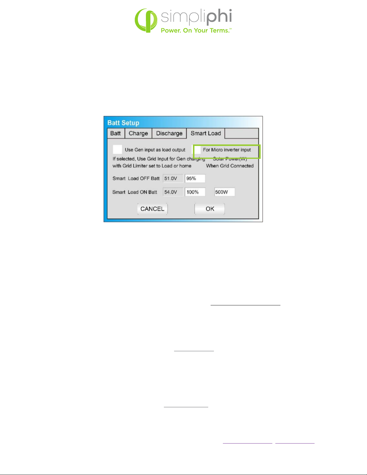
For Micro inverter input check this box for AC coupled systems
Smart Load OFF Batt10 100% (52.5 V)
Smart Load ON Batt11 30 – 95%
Notes:
1. These settings are calculated by multiplying the per-battery value by the number of batteries in the
connected battery bank.
2. Max A Charge refers to the maximum charge rate from the solar PV array. Programming this value to
the maximum value versus the reduced-stress value does not impact the AmpliPHI Battery Warranty.
3. If the Auto Generator Start is utilized, the AGS is triggered when the batteries reach this set State of
Charge (SoC) percentage. Once triggered, the generator charges the batteries until they reach
approximately 95% SoC, at which point the generator turns off. This 95% SoC parameter is not
programmable.
4. Arefers to the maximum charge rate from the grid or the generator. If the Sol-Ark is connected to
both the grid and a standby generator, the Sol-Ark prioritizes the grid as the batteries’ charging
source. Programming the Avalue to the maximum value versus the reduced-stress value does not
impact the AmpliPHI Battery Warranty.
5. By default, battery charging from the solar PV array is prioritized over generator or grid charging.
6. When the battery has reached the Absorption voltage setpoint, the Sol-Ark utilizes constant-voltage
regulation to maintain the battery at the programmed Absorption voltage. The Absorption phase lasts
until the batteries charge at 2% of the programmed Ah size. For example, one AmpliPHI 3.8 battery
(rated at 75 Ah), will remain in the Absorption charging phase until the number of Amps used to
charge the battery decreases to 1.5 Amps DC (2% of 75Ah).
7. While the AmpliPHI Battery does not require an Equalization charge, programming Equalization to
the voltage, frequency and duration outlined in the table above ensures that the Sol-Ark’s internal
SoC meter re-sets to 100% SoC every 30 days.
8. Smart Loads are no longer powered via solar and/or batteries when the batteries’ SoC level drops
below this programmed Smart Load OFF Batt value.
9. Smart Loads are powered via solar and/or batteries when the batteries’ SoC level exceeds this
programmed Smart Load ON Batt value.
10. The Sol-Ark stops charging the batteries and powering the loads from the AC Coupled solar PV array
once the batteries’ SoC level reaches the Smart Load OFF Batt value.
11. The Sol-Ark triggers the AC Coupled solar PV array to produce power (powering the loads and
charging the batteries) when the batteries’ SoC level exceeds this programmed Smart Load ON Batt
value.
SimpliPhi Power, Inc. |3100 Camino Del Sol |Oxnard, CA 93030, USA |(805) 640-6700 | info@simpliphipower.com |SimpliPhiPower.com
|
14
|
REV202008141736
© SIMPLIPHI POWER
CAUTION: WHILE SOL-ARK SETTINGS MUST BE ADJUSTED WITH ANY CHANGE IN
THE PAIRED QUANTITY OF STANDARD (NON-COMMUNICATIONS) PHI BATTERIES,
AN INCREASE OR DECREASE IN THE NUMBER OF AMPLIPHI BATTERIES IN A BANK
RESULTS IN AUTOMATICALLY ADJUSTED CAPACITY AND CHARGE/DISCHARGE
CURRENT SETTINGS IN THE SOL-ARK EQUIPMENT. SIMPLIPHI ASKS THAT YOU CHECK
THE ADJUSTED PARAMETERS’ VALUES HAVE AUTOMATICALLY UPDATED
CORRECTLY.
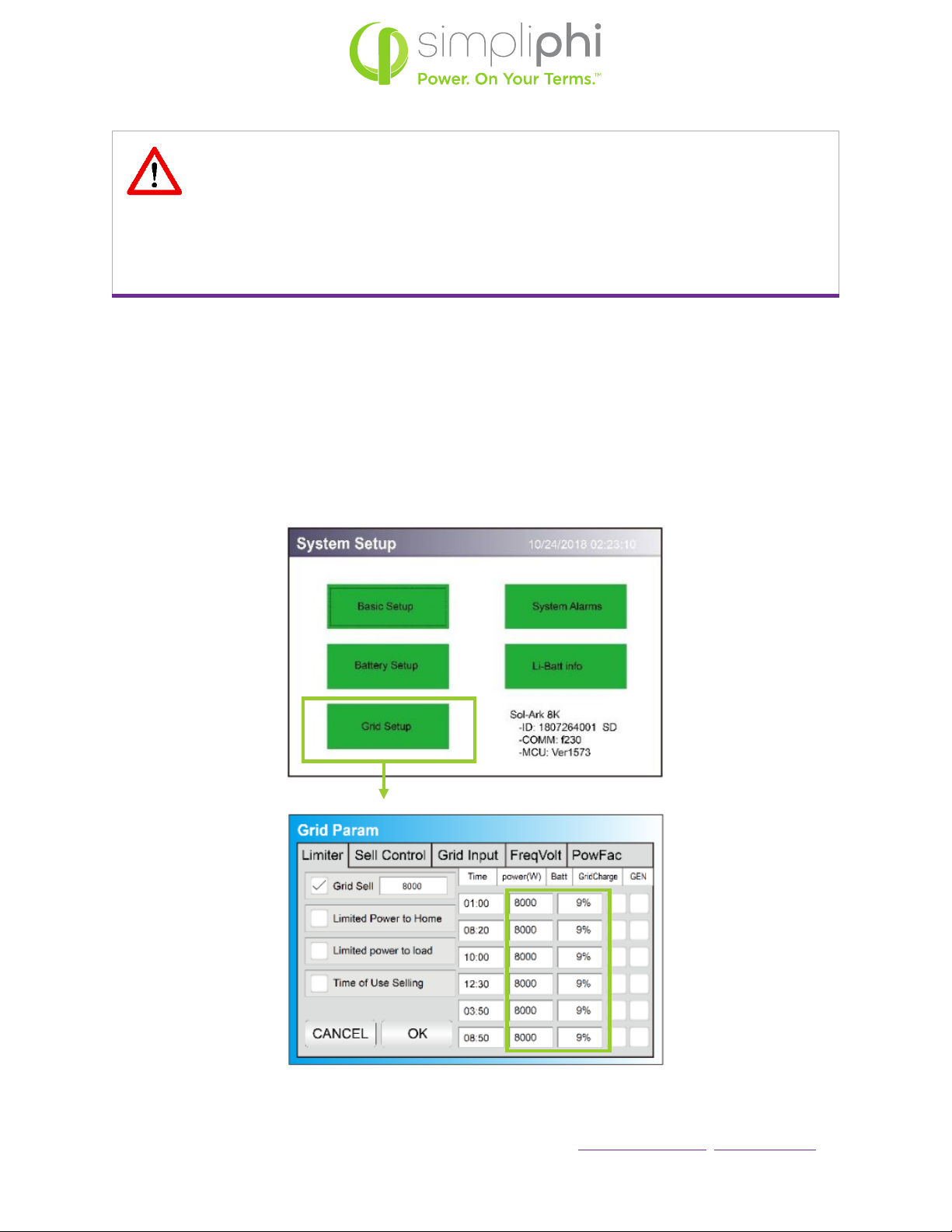
4.3 – Grid Setup
The Sol-Ark’s Grid Setup menu includes many advanced features (refer to Section 5 of this Guide). Regardless
of the features used, the AmpliPHI battery bank should never discharge more than its maximum continuous
discharge rate. Furthermore, to maintain the AmpliPHI batteries’ optimal (10,000-cycle level) life, also do not
discharge the battery bank to a State of Charge (SoC) level less than 20%. These details are controlled in the
Grid Setup menu’s Limiter tab. (Figure 9)
Figure 9: Limiter Tab in Grid Setup menu

SimpliPhi Power, Inc. |3100 Camino Del Sol |Oxnard, CA 93030, USA |(805) 640-6700 | info@simpliphipower.com |SimpliPhiPower.com
|
15
|
REV202008141736
© SIMPLIPHI POWER
The power (W) column in Figure 4 above dictates the maximum amount of power pulled from the batteries and
should be set to the AmpliPHI battery bank’s maximum discharge rate in AC Watts. To calculate the connected
AmpliPHI battery bank’s maximum discharge Watts (AC):
1. Multiply the number of batteries in the bank by the maximum discharge rate (ADC) per battery
a. AmpliPHI 3.8 battery max. discharge rate = 37.5 ADC per battery
2. Convert the battery bank’s DC discharge current to DC discharge watts.
3. Apply the discharge efficiency.
The following Tables 2 and 3 describe the continuous power output limitations of the AmpliPHI 3.8 model
batteries. Populate the power (W) column according to these tables.
Populate the Batt column to the right of the power (W) column according to the degree to which you wish to
discharge the battery bank. Again, to maintain the AmpliPHI batteries at the 10,000-cycle life level, do not
populate the Batt column with any value less than 20%.
Table 2 – Conversion from DC to AC Discharge Limit for 1 to 6 AmpliPHI 3.8 Batteries
A B C D E
# of Parallel Batteries DC Current Limit ADC X VDC (48) WDC X Discharge
Efficiency (95%)
MAX Battery Output
(WAC)
1 37.5 Amps DC 1,800 Watts DC 1,710 Watts AC 1,710 Watts AC
2 75 ADC 3,600 WDC 3,420 WAC 3,420 WAC
3 112.5 ADC 5,400 WDC 5,130 WAC 5,130 WAC
4 150 ADC 7,200 WDC 6,840 WAC 6,840 WAC
5 187.5 ADC 9,000 WDC 8,550 WAC 8,550 WAC*
6 225 ADC 10,800 WDC 10,260 WAC 10,260 WAC*
Note: Sol-Ark’s Manual shows these power (W) parameters programmed to 1,000 Watts × PHI Battery
Quantity. While there is no harm in using this approximation, the greater values outlined in the tables above
may be used.
SimpliPhi Power, Inc. |3100 Camino Del Sol |Oxnard, CA 93030, USA |(805) 640-6700 | info@simpliphipower.com |SimpliPhiPower.com
|
16
|
REV202008141736
© SIMPLIPHI POWER
5.0 –Use Cases & Application Notes
Sol-Ark equipment includes many advanced programming features and a variety of modes (more than one
mode can be used simultaneously). This section of the Guide will outline the system programming and setup
basics for common use cases. However, refer also to the Sol-Ark Manual for all installation requirements
relevant to the application at hand.
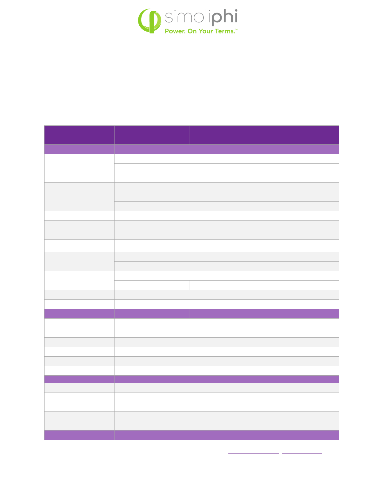
Table 3 – Sol-Ark Grid Settings
System Setup > Grid Setup 80% DoD 90% DoD 100% DoD
(10k cycle warranty) (5k cycle warranty) (3.5k cycle warranty)
> Limiter Tab
Grid Sell
check this box when exporting solar PV power to the grid
(Net Energy Metering agreement required)
set the numerical value to the maximum number of exporting Watts
Limited Power to Home
check this box when powering both the critical loads sub-panel and
the main house breaker panel using solar and/or battery,
without exporting energy to the grid (limiter sensors required)
Limited power to load check this box when powering the critical loads sub-panel using solar and/or battery
Time of Use Selling
check this box when discharging the batteries during set times
(either the Grid Sell or Limited Power to Home box must also be checked)
Time
sets the time at which the batteries discharge to power both the critical loads sub-panel and the main
house breaker panel (limiter sensors required)
power (W)
sets the maximum amount of power discharged from the batteries during the set time
do not exceed the Wattage values listed in Tables 2 or 3 above
Batt
the percentage SoC to which the batteries discharge during the set time
20% 10% 0%
Grid Charge check this box to allow for grid-to-battery charging during the set time
GEN check this box to allow for gen-to-battery charging during the set time
> Sell Control Tab 80% DoD 90% DoD 100% DoD
General Standard
check this box when a generator is wired to the Grid Input
or to use the Protect Param settings listed in the Grid Input tab
UL 1741 & IEEE 1547 check this box for grid sell compliant functionality (default)
CA Rule 21 check this box for compliance with CA Rule 21
UL 1741SA check this box for compliance with HECO Rule 14H and/or PREPA
GEN connect to Grid input check this box when a generator is wired to the Grid Input
> Grid Input Tab
Grid Frequency select 50 Hz or 60 Hz
Grid Type
select 120/240V split phase (North America),
or contact SimpliPhi to special-order 220V single phase or 120/208V 3 phase
Protect Param
leave as default values when UL 1741 & IEEE 1547 are enabled
frequency values may change when a generator is wired to the Grid Input
> FreqVolt tab refer to the Sol-Ark Manual for Puerto Rico or Kauai-specific settings
SimpliPhi Power, Inc. |3100 Camino Del Sol |Oxnard, CA 93030, USA |(805) 640-6700 | info@simpliphipower.com |SimpliPhiPower.com
|
17
|
REV202008141736
© SIMPLIPHI POWER
5.1 – AC Coupled
In an AC Coupled system setup, the grid-tie inverter(s) output – string or micro-inverters – is wired to the Sol-
Ark’s Generator Input (40A double-pole breaker) and the For Micro inverter input box in the Smart Load tab
of the Battery Setup menu must be checked:
Figure 10: Smart Load Tab in Batt Setup menu
The Sol-Ark-8K is limited to a maximum of 7 kW of AC Coupled solar PV, and the Sol-Ark-12K is limited to 7.6
kW of AC Coupled solar. AC Coupled systems can operate in Grid Sell / Grid-Tied with Battery Backup, Limited
to Home, Limited to Load, or Time of Use Selling modes.
5.2 – Grid Sell / Grid-Tied with Battery Backup
A net energy metering agreement with the utility company is required in order to sell energy from the solar PV
array to the grid. In this mode, the Sol-Ark prioritizes powering all loads (on both the critical loads sub-panel
and the main house breaker panel) from solar PV first (if available), then (2) grid, (3) generator, and (4)
batteries. In the event of a grid failure, the batteries will power the critical loads sub-panel only. Take care to
size the battery bank accordingly; in a grid failure scenario, the Sol-Ark does not limit the batteries’ maximum
current output. The maximum power draw (kW) on the critical loads sub-panel should not exceed the maximum
continuous discharge rate of the AmpliPHI battery bank. Refer to the Discharge Calculation in Section 3 of this
Guide:
# ≥ ÷
Discharge Example:
•Circuits on the critical loads sub-panel amount to a maximum potential power draw of 30 Amps at 240
VAC, or 7.2 KwAC
•Sol-Ark-8K inverter DC-to-AC efficiency is 95.5%
•AmpliPHI 3.8 battery has a maximum continuous discharge rate of 1.92 kWDC
# ≥7.2 ÷ 0.955
1.92
= 3.9
SimpliPhi Power, Inc. |3100 Camino Del Sol |Oxnard, CA 93030, USA |(805) 640-6700 | info@simpliphipower.com |SimpliPhiPower.com
|
18
|
REV202008141736
© SIMPLIPHI POWER
A properly sized AmpliPHI battery bank based on the maximum draw of the critical loads sub-panel has a
minimum of 4 batteries, even in this Grid-Tied with Battery Backup application. Note also that during a grid
failure, the critical loads’ maximum energy draw (kWh) is also limited by the battery bank’s capacity.
5.3 – Limited to Home
Checking the Limited power to Home box in the Limiter tab of the Sol-Ark’s Grid Setup / Grid Param menu
allows for all loads* (on both the critical loads sub-panel and the main house breaker panel) to be powered using
the connected solar PV and/or batteries. The Sol-Ark prioritizes powering these loads from solar PV first (if
available), then (2) grid, (3) generator, and (4) batteries. To prioritize the batteries’ use over the grid or
generator during specific set times, also use the Time of Use Selling mode.
*While the Limited to Home mode allows for all loads to be powered using solar PV and/or batteries, the Sol-
Ark prioritizes powering loads on the critical loads sub-panel first, and loads on the main house breaker panel
are offset by solar (and/or batteries, during Time of Use Selling mode times) as much as possible. If the loads’
draw exceeds the available power from the solar PV array and (with Time of Use Selling mode also in play) the
batteries have also discharged to their minimum programmed SoC percentage level, the Sol-Ark will then
resort to powering loads using grid power.
CAUTION: IN LIMITED TO HOME MODE, LIMITER SENSORS ARE REQUIRED TO
ENSURE THAT THE HOME’S MAIN BREAKER PANEL CIRCUITS ARE POWERED
WITHOUT EXPORTING ENERGY TO THE GRID.
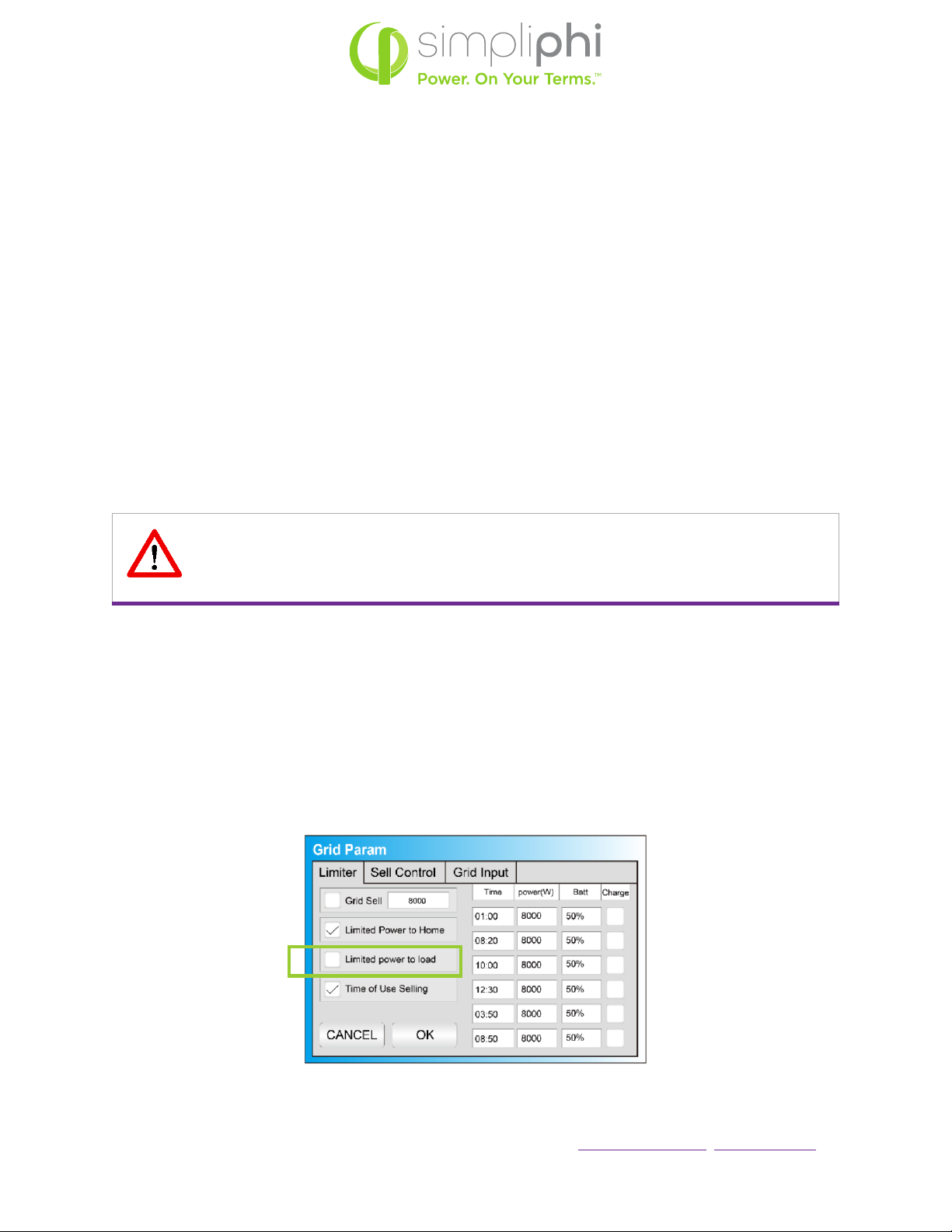
5.4 – Limited to Load
Checking the Limited power to load box in the Limiter tab of the Sol-Ark’s Grid Setup / Grid Param menu
discharges the battery to power the critical loads sub-panel’s loads. The Limited to Load mode does not allow
for any solar or battery energy to power the main house breaker panel and it does not allow for any solar or
battery energy to be exported to the grid.
Figure 11: Limiter Tab in Grid Setup Menu
SimpliPhi Power, Inc. |3100 Camino Del Sol |Oxnard, CA 93030, USA |(805) 640-6700 | info@simpliphipower.com |SimpliPhiPower.com
|
19
|
REV202008141736
© SIMPLIPHI POWER
5.5 – Time of Use Selling / Energy Arbitrage
Discharge batteries to power circuits during specific set times. Program these times to coincide with the utility
company’s peak pricing times to avoid high energy charges from the utility.
Homeowners who have a net energy metering agreement with the utility company can use both Grid Sell and
Time of Use Selling modes to sell solar PV and battery energy (until the minimum programmed SoC percentage
level) back to the grid during peak sun-hour times and then discharge the batteries during programmed times,
usually in the afternoon and evening. Depending on whether Limited power to load or Limited Power to Home
is enabled, the batteries will power either the critical loads sub-panel only (Limited to Load) or the critical loads
sub-panel and the main house breaker panel (Limited to Home) during the Time of Use Selling time period.
Make sure to size the battery accordingly. (Refer to the Discharge Example in the Grid Sell / Grid-Tied with
Battery Backup section of this Guide for battery bank sizing when batteries power the critical loads sub-panel
only. Refer to the Discharge Example in Section 3 of this Guide for battery bank sizing when the batteries
power both the critical loads sub-panel and the main house breaker panel.)
Homeowners who do not have a net energy metering agreement use both Limited Power to Home and Time of
Use Selling modes to prioritize powering all loads (circuits both on the critical loads sub-panel and the main
house breaker panel) from the solar and/or batteries during programmed times. Refer to the Discharge
Example in Section 3 of this Guide for battery bank sizing when the batteries power both the critical loads sub-
panel and the main house breaker panel.
CAUTION: EITHER THE GRID SELL OR THE LIMITED POWER TO HOME MODE (CHECK
THE APPROPRIATE BOX IN THE GRID SETUP / GRID PARAM MENU) MUST BE USED IN
CONJUNCTION WITH TIME OF USE SELLING.
During Time of Use Selling times, loads are powered from solar first (if available), batteries second, and the grid
third (if batteries have discharged to their programmed minimum SoC percentage level).
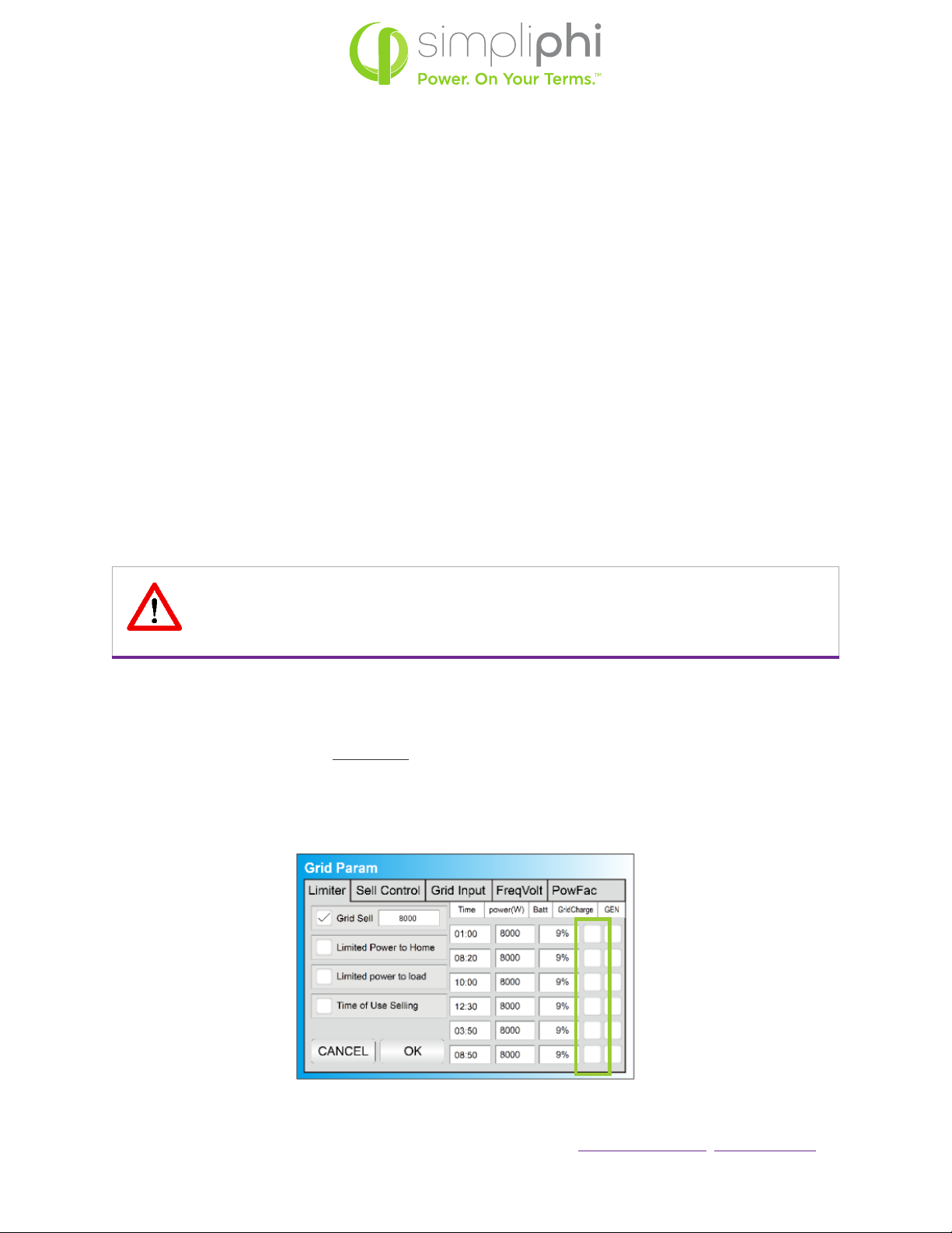
Make sure the GridCharge box is unchecked during peak pricing times so that the batteries do not charge
when energy from the utility company is most expensive (see Figure 12).
Figure 12 – Limiter Tab in Grid Setup menu
SimpliPhi Power, Inc. |3100 Camino Del Sol |Oxnard, CA 93030, USA |(805) 640-6700 | info@simpliphipower.com |SimpliPhiPower.com
|
20
|
REV202008141736
© SIMPLIPHI POWER
5.6 – Off-Grid
The Sol-Ark automatically operates in Off-Grid mode when it does not detect a grid connection.
In an Off-Grid system setup, all the home’s loads are connected to the Sol-Ark’s Load Output (50A double-pole
breaker).
Do not use the Sol-Ark’s Grid Sell and Limited to Home modes in an off-grid system setup.
Check the Limited power to load box in the Limiter tab of the Sol-Ark’s Grid Setup / Grid Param menu to allow
for the batteries’ power to discharge to the connected loads.
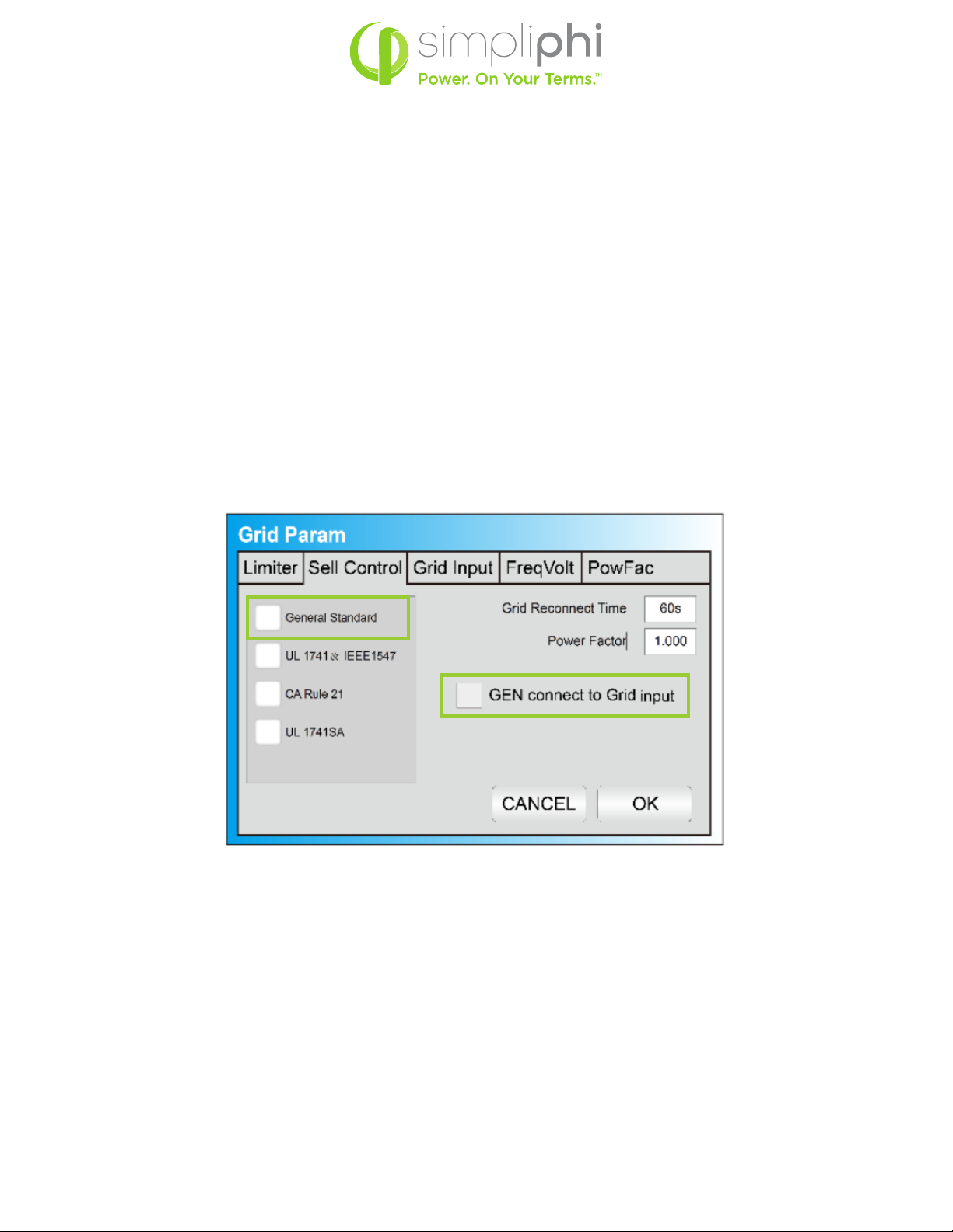
5.7 – Generators
The Sol-Ark’s built-in Auto Generator Start functions as a 2-wire automatic switch.
The Sol-Ark’s Grid Input breaker can be used as the generator’s input breaker. In this scenario, check the
General Standard box and the GEN connect to Grid input box in the Grid Param menu’s Sell Control tab:
Figure 13 – Sell Control Tab in Grid Setup menu
Due to the fact that many generators’ output frequency is usually less precise than the grid’s, the frequency
parameters in the Grid Param menu’s Grid Input tab may also need adjustment to accommodate a wider
frequency range:
This manual suits for next models
2
Table of contents
Popular Inverter manuals by other brands


Mastervolt
Mastervolt AC MASTER 12/200-230V user manual

Parkside
Parkside PSE 2800 B2 Operation manual

Mitsubishi Electric
Mitsubishi Electric FR-HEL-0.4K instruction manual

Salicru
Salicru EQUINOX EQX2 2001-S user manual

Winco
Winco ULPSS20B2W/A Installation and operator's manual

SolaX Power
SolaX Power X1-Hybrid user manual


-L1 quick guide")


