Parker 890SD Instruction manual

890 QuickStart Manual
890SD (Standalone) Drives
Frames E & F with STO SIL3/PLe
HA501030U000 Issue 4
aerospace
climate control
electromechanical
filtration
fluid & gas handling
hydraulics
pneumatics
process control
sealing & shielding
ENGINEERING YOUR SUCCESS.
The full Product Manual is available on line at www.parker.com/ssd

Page 1
890
Quickstart Manual
890SD (Standalone) Drive
Frames E & F with STO SIL3/PLe
HA501030U000 Issue 4
Copyright 2016 Parker Hannifin Manufacturing Ltd
All rights strictly reserved. No part of this document may be stored in a retrieval system, or transmitted in any form or by any means
to persons not employed by a Parker Hannifin Manufacturing Ltd., company without written permission from Parker Hannifin
Manufacturing Ltd. Although every effort has been taken to ensure the accuracy of this document it may be necessary, without notice,
to make amendments or correct omissions. Parker Hannifin Manufacturing Ltd., cannot accept responsibility for damage, injury, or
expenses resulting there from.
1) What is Safe Torque Off (STO)?
It is an electronic means of preventing the 890 drive from delivering torque and power to its
connected motor. The 890 drive contains this feature as standard. It is a two channel, hardware
implemented system. It has the highest possible safety rating for a variable speed drive. It is
certified by BGIA, the German Trades Association for Industrial Safety, to Performance Level e
(PLe) for a category 3 implementation to EN ISO 13849-1 with an equivalent Safety Integrity Level
3 (SIL 3).
All STO connections are made at terminal block X11.
2) Where Could STO be Used?
In safety control schemes for safety ratings up to category 3 PLe or SIL3. To replace expensive but
less reliable drive output contactors, including for emergency stop purposes. The 890 STO function
can also be used to implement Safe Stop 1 (SS1).
3) To Use the STO Function - What Should I Do Next?
Read and observe all the requirements in the STO chapter 6 of the Engineering Reference Manual,
use the appropriate standards and risk assessments.
4) Replacing a NON STO Drive OR the STO Function is Not Required - What Should I Do Next?
Simply disable the STO function by Linking –
X11/01 and X11/03 to X14/03 (24V) and separately link X11/02 OR X11/04 to X14/04 (0V).
The rest of this quick start manual then applies.
5) On Start Up the MMI Displays “***Tripped*** SAFE TORQUE OFF” or
on a 6511 MMI “ASTO ” . Why?
Because no connections to X11/01 OR X11/03, they are at 0V, the STO feature has been enabled
i.e. failed safe. Simply disable the STO feature by fitting the links described in item 4) above.

Page 2

Page 3
C o n t e n t s
Page
Safety...................................................................................................................................................................... 5
Hazards to Personnel 5
Application Risk 5
Risk Assessment 6
Accessibility 6
Protective Insulation 6
RCDs 6
Introduction........................................................................................................................................................... 7
About this QuickStart 7
Overview................................................................................................................................................................ 8
Installation............................................................................................................................................................. 9
Mounting Dimensions 10
890SD Frame E Power Connections..............................................................................................................11
890SD Frame F Power Connections..............................................................................................................12
890SD Control Connections............................................................................................................................13
890SD Feedback Connections........................................................................................................................14
Drive Start-up...................................................................................................................................................... 15
Before Applying Power: 15
Drive Set-up ........................................................................................................................................................15
Motor Data 15
Quick Setup Parameters 16
Autotune 16
Running in Local 17
Running in Remote 17
Appendix A: Using the 6901 Keypad .............................................................................................................18
The Menu Structure 19
Appendix B: Analog and Digital I/O................................................................................................................20
890SD Control Terminals 21
Appendix C: Electrical Ratings....................................................................................................................... 23
Appendix D: Compliance..................................................................................................................................27
EMC Emissions 27
EMC Connections 27
Planning Cable Runs 28

Page 4

Page 5
Safety
IMPORTANT
Please read this information BEFORE installing the equipment.
Hazards to Personnel
WARNING!
This equipment can endanger life through rotating machinery and high voltages. Failure
to observe the following will constitute an ELECTRICAL SHOCK HAZARD.
Metal parts may reach a temperature of 70 degrees Centigrade in operation.
Before working on the equipment, ensure isolation of the mains supply from terminals
L1, L2 and L3. The equipment contains high value capacitors which discharge slowly after
removal of the mains supply. Wait for at least 3 minutes for the dc link terminals (DC+ and
DC-) to discharge to safe voltage levels (<50V). Measure the DC+ and DC- terminal
voltage with a meter to confirm that the voltage is less than 50V.
Do not apply external voltage sources (mains supply or otherwise) to any of the braking
terminals (DBR+, DBR-, DC+, INT or EXT).
Application Risk
The specifications, processes and circuitry described herein are for guidance only
and may need to be adapted to the user's specific application.
Parker Hannifin Manufacturing Limited does not guarantee the suitability of the
equipment described in the Manual for individual applications.
This manual is for anyone
installing, operating and
servicing this unit.

Page 6
Risk Assessment
Under fault conditions, power loss or other operating conditions not intended, the
equipment may not operate as specified. In particular:
The motor speed may not be controlled
The direction of rotation of the motor may not be controlled
The motor may be energized
If the STO feature of the 890 drive is to be used, the user must undertake a risk
assessment for the application. The user must then verify that their design, which
includes the 890 drive, satisfies the Performance Level (PL) or Safety Integrity Level
(SIL) required by the risk assessment.
Under no circumstances must the STO feature be used without first reading and fully
understanding chapter 6 (Safe Torque Off) of the Engineering Reference Manual. All
safety warnings therein must be observed.
Accessibility
All live power terminals are IP20 rated only, since the equipment is intended to be
installed within a normally-closed cubicle or enclosure, which itself requires a tool to
open.
Protective Insulation
All control and signal terminals are SELV, i.e. protected by double insulation.
Ensure all wiring is rated for the highest system voltage.
NOTE Thermal sensors contained within the motor must be single/basic insulated.
All exposed metalwork in the Drive is protected by basic insulation and bonding to
a safety earth.
RCDs
Not recommended for use with this product. Where their use is mandatory, use only
Type B RCDs (EN61009).
Caution
This is a product of the restricted sales distribution class according to IEC 61800-3. It
is designated as “professional equipment” as defined in EN61000-3-2. Permission of
the supply authority shall be obtained before connection to the low voltage supply.

Page 7
Introduction
The 890SD Standalone Drive is designed for speed control of standard ac 3-phase motors.
Control it remotely using configurable analogue and digital inputs and outputs.
Control it locally using the 6901 Keypad.
Use the Design System Explorer Configuration Tool (DSE 890) to give access to parameters,
diagnostic messages, trip settings and application programming.
Fit Options to the unit to give serial communications and closed loop speed control.
IMPORTANT:
Motors used must be suitable for Inverter duty.
About this QuickStart
This QuickStart will:
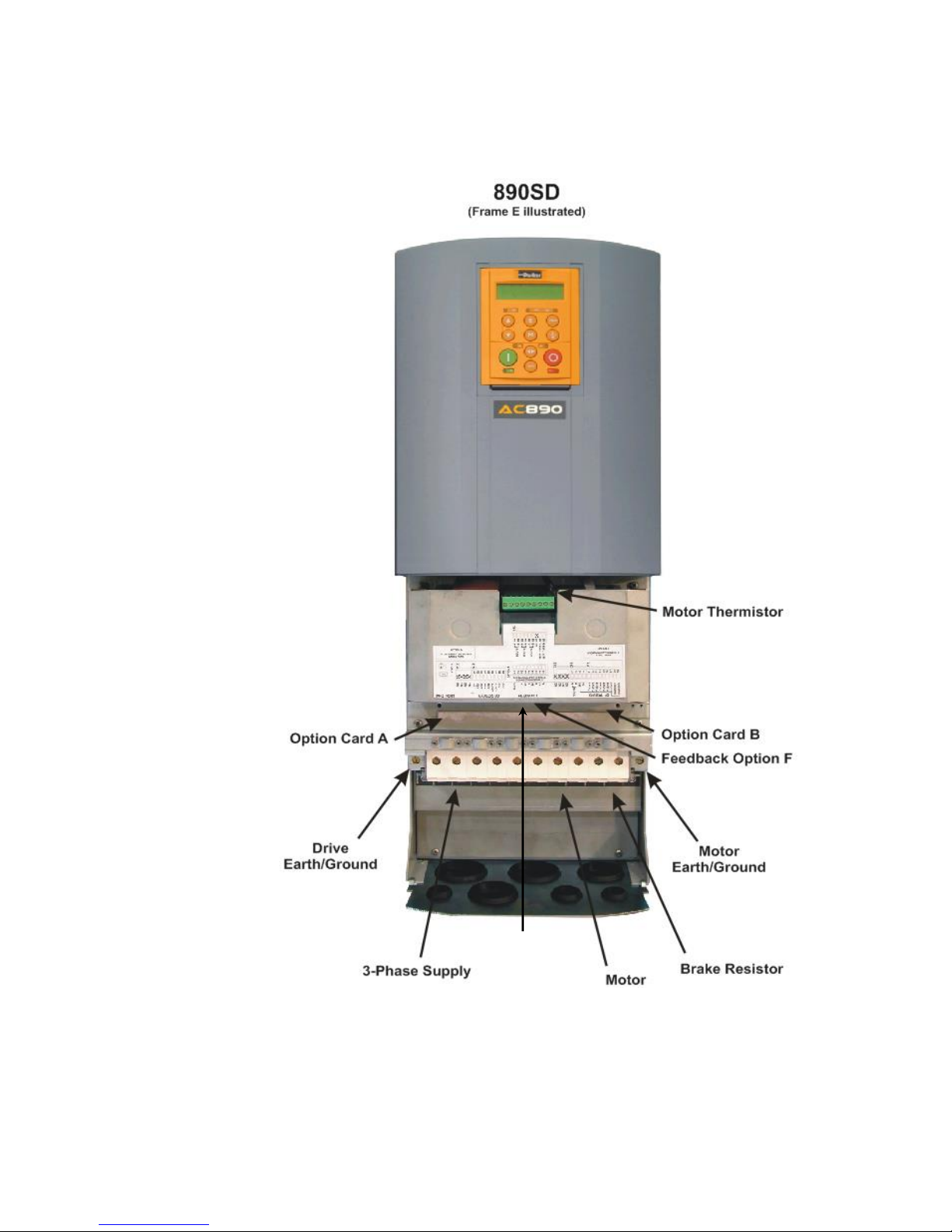
Familiarise you with the terminals and operation of the unit.
Provide *basic installation details and a quick set-up procedure.
Show you how to Autotune the drive and start the motor.
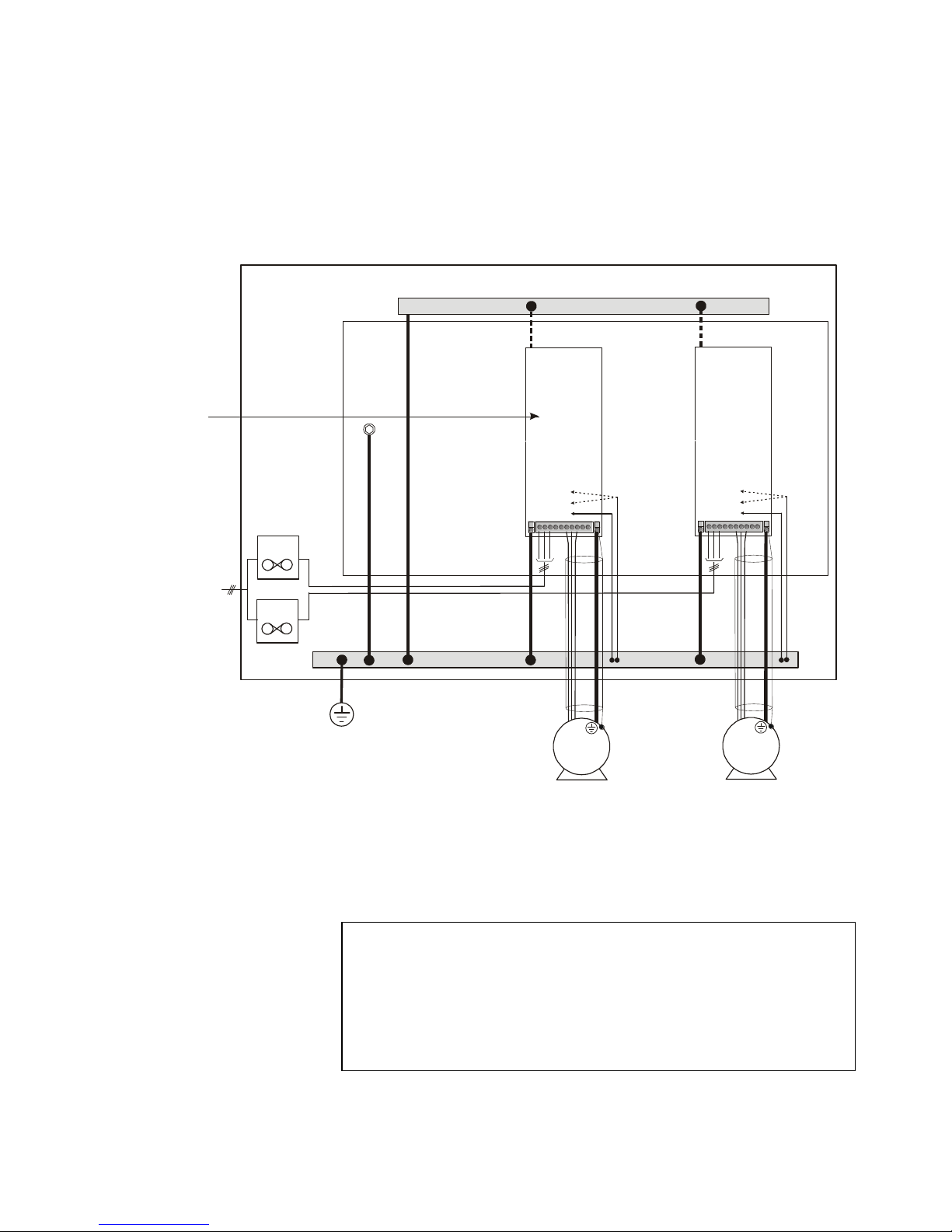
* Because the 890 is a system product and we have no knowledge of your application, we detail the
quickest way to power-up the drive using a simple earthing scheme with minimal control wiring.
Refer to the full Engineering Reference Manual for items not covered in this QuickStart.
Provided with every 890 unit is a :
Quickstart
890 Installation Kit and instruction leaflet
6901 Keypad
Customer-ordered Options
This QuickStart assumes that:
You are a qualified technician with experience of installing this type of equipment.
You are familiar with the relevant standards and Local Electric Codes (which take precedence).
You have read and understood the Safety information provided at the front of this QuickStart.
You realise that this guide contains only basic information and that you may need to refer to the
Engineering Reference Manual to complete your installation.
You are not using the Safe Torque Off (STO) feature of this product and that you will disable it as
instructed in this QuickStart manual.
Safety Note –Use of the STO feature requires full compliance with the STO chapter 6 of the
Engineering Reference Manual to which the user must first refer.

Page 8
Overview
Safe Torque Off

Page 9
Installation
A simplified installation is shown below. This installation is not EMC compliant. For European
installations and countries with EMC legislation refer to the 890 Engineering Reference Manual,
Appendix C.
KEY
B
Back-plate
C
Cubicle
D
Control Wiring
terminals
G
Supply
Protective
Earth/Ground
K
Motor
(M1, M2, M3)
L
3Power
Supply Cable
(L1, L2, L3)
P
Fuse or circuit
breaker
* Permanent Earthing
The unit must be permanently earthed according to EN 50178: For
permanent earthing, one conductor, PE1, of >10mm² cross-section is
required; or two individual incoming protective earth conductors, PE1 &
PE2, of <10mm² cross-section. Each earth conductor must be suitable for
the fault current according to EN 60204.
L1
L2
L3
L
C
D
G
24V
B
*
PE1
G
P
P
PE2
*
PE1
M1
M2
M3
K
0V
X12/01
X14/04
M1
M2
M3
K
0V
X12/01
X14/04
890SD 890SD
PE2

Page 10
Mounting Dimensions
W
H1
D
W1
H
J J K
L
M
The units must be installed in a cubicle. Mount the drive using the keyholes and slots.
Models
Maximum
Weight:
kg/lbs
H
H1
W
W1
D
Air Clearance
Fixings
J
K
L
M
Frame E
32.5/72
668.6
(26.3)
630.0
(24.8)
257.0
(10.1)
150.0
(5.9)
312
(12.3)
0
(zero)
25
(1)
70
(2.8)
70
(2.8)
Use M6
fixings
Frame F
41/90.4
720.0
(28.3)
700.0
(27.6)
257.0
(10.1)
150.0
(5.9)
355.0
(14.0)
0
(zero)
25
(1)
70
(2.8)
70
(2.8)
Use M6
fixings
All dimensions are in millimeters (inches)
Ventilation
The drive gives off heat during normal operation. Mount it to allow free flow of air through the
ventilation slots and heatsink. The mounting surface must be normally cool. Maintain the minimum air
clearances. Clearances are additive when mounting two 890 units together. Ensure heat from
adjacent equipment is not transmitted. Maintain the clearance requirements of other equipment.
Environmental Conditions
Operating ambient temperature 0°C to 45°C (32°F to 113°F)
Enclosure rating IP20 –UL(cUL) Open type
Atmosphere Dust free, non flammable, non-corrosive, <85% humidity,
non-condensing

Page 11
890SD Frame E Power Connections
Motor
5
PE1
All screens terminated using
a gland at the gland plate
3-Phase Supply
6
5
67
Brake
Resistor
8
Connect motor leads to M1/U, M2/V, M3/W.
Maximum wire sizes::
Frame E: 50mm2/1AWG (without crimp)
70mm2/ 1/0AWG (with crimp)
Connect the earth/ground wire from the terminal
box of the motor directly to the earth/ground
terminal.
Maximum wire sizes:
Frame E: 50mm2/1AWG (without crimp)
70mm2/ 1/0AWG (with crimp)
If not using shielded cable, run motor leads in an
enclosed metal conduit bonded to the drive at
one end and the motor at the other.
Connect the earth/ground wire to the
earth/ground terminal.
Maximum wire sizes:
Frame E: 50mm2/1AWG (without crimp)
70mm2/ 1/0AWG (with crimp)
5
Connect the 3-phase supply.
Maximum wire sizes:
Frame E: 50mm2/1AWG (without crimp)
70mm2/ 1/0AWG (with crimp)
6
7
Connect the brake resistor.
Maximum wire sizes:
Frame E: 50mm2/1AWG (without crimp)
70mm2/ 1/0AWG (with crimp)
An External Braking Resistor is optional.
Connect it between DBR+ and DBR- for
high inertial loads.
DO NOT apply external voltage sources
(mains supply or otherwise) to the braking
terminals.
We recommend using a thermal overload
switch to protect the braking circuit.
8

Page 12
890SD Frame F Power Connections
Connect motor leads to M1/U, M2/V, M3/W.
Maximum wire sizes::
Frame F: 95mm2/ 4/0AWG (without crimp)
95mm2/ 4/0AWG (with crimp)
Connect the earth/ground wire from the terminal
box of the motor directly to the earth/ground
terminal.
Maximum wire sizes:
Frame F: 95mm2/ 4/0AWG (without crimp)
95mm2/ 4/0AWG (with crimp)
If not using shielded cable, run motor leads in an
enclosed metal conduit bonded to the drive at
one end and the motor at the other.
Connect the earth/ground wire to the
earth/ground terminal.
Maximum wire sizes:
Frame F: 95mm2/ 4/0AWG (without crimp)
95mm2/ 4/0AWG (with crimp)
5
Connect the 3-phase supply.
Maximum wire sizes:
Frame F: 95mm2/ 4/0AWG (without crimp)
95mm2/ 4/0AWG (with crimp)
6
7
Connect the 115 or 220Vac auxiliary
supply for the internal fans to AUX 1 and
AUX 2 (in any order).
See block 5 of the Model Number:
1F = 115Vac, 2F = 220Vac.
8
Connect the brake resistor.
Maximum wire sizes:
Frame F: 95mm2/ 4/0AWG (without crimp)
95mm2/ 4/0AWG (with crimp)
An External Braking Resistor is optional.
Connect it between DBR+ and DBR- for
high inertial loads.
DO NOT apply external voltage sources
(mains supply or otherwise) to the braking
terminals.
We recommend using a thermal overload
switch to protect the braking circuit.
9
56
5
67
Bond the motor cable
screen to the drive and
motor, as close as
possible to both terminals
PE1
Terminate all
control cable screens
using a gland at the
gland plate
auxiliary
supply
terminals
(fan)
M1/U M2/V M3/W
3-Phase Supply
Motor
8
L1 L2 L3
9
brake
resistor
terminals

Page 13
890SD Control Connections
This is a basic connection diagram.
For more detailed information on control connections, refer to Appendix B.
The control terminals will accept a single wire of
size 1.5mm2/16AWG. For two wires per terminal,
use smaller gauge wire such as 0.5mm2/22AWG.
Connect volt-free
contacts as required
RUN (maintained contact)
terminal X14/03 and
terminal X15/02
B
Sequencing
Connect a 10kΩ potentiometer at
terminal block X12 (Analog I/P 3)
High (CW): terminal X12/08
Wiper: terminal X12/04
Low (CCW): terminal X12/01
Connect the shield to earth/ground
A
Speed Reference
OR
External 2-wire speed reference
between
terminals X12/01(-) and X12/04(+)
Connect the shield to earth ground
SPEED FEEDBACK
10V = ±100% speed at
terminal X12/0 6
TORQUE FEEDBACK
10V = ±200% torque
at terminal X12/07
ANALOG COMMON
0V at terminal X12/0 1
Analog
Outputs
DRIVE HEALTH
Relay dry contact
(24V rated) at
terminal X14/01 and
terminal X14/02
RUNNING
24V sourcing output
at terminal X15/08
ZERO SPEED
24V sourcing output
at terminal X15/09
DIGITAL COMMON
0V at terminal X14/04
Digital
Outputs
Connect motor thermal
switch or thermistor to
terminals X16/08 &
X16/09. Drive will trip
when the thermal switch
opens, or when the
thermistor resistance
exceeds 4kmaximum
(PTC Type A : IEC 34-11
Part 2)
If the motor does not
have a protective device
(thermistor), jumper
these terminals. The
drive needs the
thermistor inputs
connected for it to run.
C
Thermistor
To disable STO:
Connect X14/03 to X11/01 and
X11/03
Connect X14/04 to X11/04
To use the STO feature the user
must read and fully understand
chapter 6 of the Engineering
Reference Manual.
D
Safe Torque Off
(disabled)
X11

Page 14
890SD Feedback Connections
Incremental Pulse Encoders
The default settings for the drive are for 2048 line,
quadrature, incremental pulse encoders with differential
outputs operating from a 10VDC supply.
Z channel (Marker pulse) connections are not
necessary for running the drive, but inputs are
provided for positioning and servo applications. The
supply voltage to the encoder is set in the Quick
Setup menu. Range 10 VDC to 20 VDC
Use the Keypad to set the following options:
Supply Voltage - PULSE ENC VOLTS
Number of lines per revolution - ENCODER LINES parameter
* Encoder direction - ENCODER INVERT
* Used to match the encoder direction to the motor direction. When TRUE, changes the sign of the
measured speed and the direction of the position count. It is necessary to set up this parameter when
in CLOSED-LOOP VEC mode, as the encoder direction must be correct for this mode to operate.
Using other types of encoders requires the 890 DSE Configuration Tool and the setting of other
parameters. Refer to the 890 Engineering Reference Manual for details of these parameters.
This section is only for closed loop vector and induction servo applications.
Skip this page if there is no encoder or resolver mounted on the motor.
Use 3-pair or 4-pair,
individually shielded encoder
cable, Belden model 8777 or
equivalent.
OPTION F
OPTION F Terminal Block
01 Shield
02 Supply –
03 Supply +
04 Channel Z/
05 Channel Z
06 Channel B/
07 Channel B
08 Channel A/
09 Channel A

Page 15
Drive Start-up
Before Applying Power:
Read the Safety section at the front of the QuickStart.
Ensure that all local electric codes are met.
Check for damage to equipment.
Check for loose ends, clippings, filings, drilling swarf etc. lodged in the drive and
system.
Check all external wiring circuits of the system - power, control, motor and earth
connections.
Ensure that unexpected rotation of the motor in either direction will not result in
damage, bodily harm or injury. Disconnect the load from the motor shaft, if
possible.
Check the state of the Motor Thermistor and Brake Resistor connectors. Check
external run contacts are open. Check external speed setpoints are all at zero.
Ensure that nobody is working on another part of the system which will be
affected by powering up.
Ensure that other equipment will not be adversely affected by powering up.
Check motor stator connections are correctly wired for Star or Delta as necessary
for drive output voltage.
Check that the STO feature has been disabled. See page 11 of this Quickstart
Manual.
DANGER: some motors are not suitable for use with STO. Refer to chapter 6 of
the Engineering Reference Manual for full details.
Drive Set-up
Appendix A contains information about the 6901 keypad menus and parameter names.
Motor Data
Before attempting to set up the drive, you will need some motor information. This is found on the
motor nameplate. The information you will need is listed below:
Base Volts
Base frequency
Base RPM
Full load amps
No load amps (mag current)
Connection (star or delta)
If all connections have been checked, it is time to POWER-UP the drive

Page 16
This section is only for operating in Sensorless or Closed-loop Vector modes.
If the drive is in V/Hz mode, Autotune is unnecessary and will not Enable.
Quick Setup Parameters
The following is a list of the Quick Setup parameters you must check before starting the drive. Set
only the ones marked with “x” in the table below, under the intended mode of operation.
V/Hz SV Vector
Control Mode Select the intended operating mode x x x
Max Speed Motor RPM at full process speed x x x
V/F shape Usually Linear. Choose fan curve only for fans x
Motor Current Motor full load current from motor nameplate x x x
Motor Base Freq Motor nameplate frequency x x x
Motor Voltage Motor nameplate voltage x x x
Nameplate RPM Motor nameplate RPM x x x
Motor Poles See Note x x
Pulse Enc Volts Set between 10-20V to match encoder x
Encoder Lines Pulses per Revolution of encoder x
Encoder Invert Changes polarity of encoder feedback x
Autotune Enable Drive will Autotune if started x x
Mag Current Enter the No-Load Amps from the motor nameplate x x* x*
* if perfoming a Stationary Autotune.
NOTE Some of the parameters are product code dependent, that is, they are different for each
frame size and power rating. For example, the unit will be set for either 50Hz or 60Hz
operation:
Motor Poles for 60Hz 2 poles = 3600 rpm, 4 poles = 1800 rpm, 6 poles = 1200 rpm
Motor Poles for 50Hz 2 poles = 3000 rpm, 4 poles = 1500 rpm, 6 poles = 1000 rpm
Autotune
Ensure that MAX SPEED is greater than NAMEPLATE RPM for a successful autotune.
In the QUICK SETUP menu, set AUTOTUNE ENABLE to TRUE.
On the 890CD keypad select LOCAL mode. Set SETPOINT (LOCAL) to 0.0%.
Press the green RUN button. The drive will begin autotuning. The drive will stop without errors if
autotune is successful.
Go to SYSTEM::SAVE CONFIG::APPLICATION and UP arrow to save your settings.
ROTATING AUTOTUNE
STATIONARY AUTOTUNE
Under Quick setup, set AUTOTUNE MODE to STATIONARY
Is the motor uncoupled
from the load and free
to rotate without causing
problems?
YES
NO
Under QUICK SETUP, enter the exact MAG
CURRENT in Amps (from motor data)

Page 17
Running in Local
On the keypad select LOCAL mode. The display will show the Local Setpoint : 0.0%
Use the UP arrow to set a Local Setpoint, say 20%.
Press the green RUN button. The motor will accelerate to the desired speed and maintain it. Adjust
RAMP ACCEL TIME in Quick Setup to the desired level.
Press the red STOP button. The motor will decelerate to a stop. Adjust RAMP DECEL TIME in
Quick Setup to desired level. If the drive trips on Overvoltage, extend the RAMP DECEL TIME or
connect a braking resistor. Refer to the 890 Engineering Reference Manual.
Go to SYSTEM::SAVE CONFIG::APPLICATION and UP arrow to save your settings Values are
stored during power-down.
Running in Remote
On the keypad select REMOTE mode. The display will show the remote Setpoint : ?.?% (The value
displayed depends on the external speed reference).
Dial in a speed setpoint using the Speed potentiometer until the display reads 20%.
Start the drive by closing the Start contact between terminal X14/03 and terminal X15/02. The
motor will accelerate to the desired speed and maintain it. Adjust RAMP ACCEL TIME in Quick
Setup to the desired level.
Open the Start contact. The motor will decelerate to a stop. Adjust RAMP DECEL TIME in Quick
Setup to desired level. If the drive trips on Overvoltage, extend the RAMP DECEL TIME or connect
a braking resistor. Refer to the 890 Engineering Reference Manual.
Go to SYSTEM::SAVE CONFIG::APPLICATION and UP arrow to save your settings Values are
stored during power-down.
SAVE CONFIG
M
for example
M
"UP" TO CONFIRM
PROG
SETPOINT REMOTE
0.0 %
=PROG
(NORMAL ACTION OF PROG KEY)
DISPLAYS OPERATOR MENU
SAVE CONFIG
menu at level 2
SAVE CONFIG
APPLICATION
SAVE CONFIG
SAVE CONFIG
SAVE CONFIG
menu at level 2

Page 18
Appendix A: Using the 6901 Keypad
The 6901 keypad has a two-line backlit LCD display with units and
symbols. It can be used to setup and configure the 890 in plain
language. It can also be used to operate the drive in Local mode
from its Start and Stop buttons, Jog and reverse.
Menus :
exit a menu
sub-menu or
parameter
scroll up
scroll down
Parameters :
exit
parameter
make writable
previous
parameter
next
parameter
Edit
stop editing
show PREF
(hold)
increment
value
decrement
value
To change Operating Mode:
From power-up, the keypad displays the Software Version, and then times-out to show the Remote
Setpoint.
Mode
Action
Remote to Local
Toggle between modes using the L/R key
SEQ and REF LEDs are On when in Local
Local to Remote
Toggle between modes using the L/R key
SEQ and REF LEDs are Off when in Remote
SEQ and REF LEDs are On
when in Local mode
To display the Software Version and
Voltage Rating:
Press repeatedly to display the
Welcome Screen
Press to return to the Menus
To Stop in
Local Mode:
Press
To Start in
Local Mode:
Press

Page 19
The Menu Structure
The main menus are shown below. Each menu contains parameters.
NOTE Refer to the Engineering Reference Manual for a list of available parameters.
M
OPERATOR
menu at level 1
DIAGNOSTICS
menu at level 1
QUICK SETUP
menu at level 1
SETUP
menu at level 1
SYSTEM
menu at level 1
ACMOTORDRIVE
15kW400V1.x
DOWN arrow to get to the SETUP menu -
contains all the parameters
DOWN arrow to get to the SYSTEM menu
DOWN arrow to get to the DIAGNOSTICS menu
DOWN arrow to get to the QUICK SETUP menu
This is the power-up welcome screen. If a different screen
appears, press E a few times to return to this screen.
Press the M key to get to the OPERATOR menu
Other manuals for 890SD
1
This manual suits for next models
1
Table of contents
Other Parker Inverter manuals

Parker
Parker LCMS-5000 User manual

Parker
Parker MIDIGAS 2 User manual

Parker
Parker AC30V Series User manual

Parker
Parker 890GTR Instruction manual

Parker
Parker AC10 series User manual

Parker
Parker GVI Series User manual

Parker
Parker NitroFlow Lab User manual

Parker
Parker MA3 Series User manual

Parker
Parker NitroFlow Lab User manual

Parker
Parker LINKnet AC30P Assembly instructions