manuals.online logo
Brands
  1. Home
  2. •
  3. Brands
  4. •
  5. Winco
  6. •
  7. Inverter
  8. •
  9. Winco ULPSS20B2W/A Setup guide

Winco ULPSS20B2W/A Setup guide

1
12270-00 60706-229
INSTALLATION AND
OPERATORS’ MANUAL
PACKAGED STANDBY
SYSTEM
ULPSS20B2W/A
12270-00 260706-229
SAVE THESE INSTRUCTIONS
This manual contains important instructions that
should be followed during installation and main-
tenance of the generator and batteries. Read
and understand all instructions in the manual
before starting and operating the generator set.
USING THE MANUAL
Congratulations on your choice of a Winco genera-
tor set. You have selected a high-quality, precision
engineered generator set designed and tested to
give you years of satisfactory service.
To get the best performance from your new engine
generator set, it is important that you carefully read
and follow the operating instructions in this manual.
Should you experience a problem, please follow
the “Troubleshooting Tables” near the end of this
manual. The warranty listed in the manual describes
what you can expect from WINCO should you need
service assistance in the future.
TABLE OF CONTENTS
INTRODUCTION 2
GUIDE TO PRODUCT SAFETY 3
BASIC INFORMATION
Description 4
Specifications 5
PREPARING THE UNIT
Unpacking the Unit 5
ENGINE GENERATOR INSTALLATION
Installation 5
Fuel Installation 6,7
Vapor Fuel Pressure Tables 8
Fuel Conversions 8
Battery Installation 9
Connecting Battery Charger 11
TRANSFER SWITCH INSTALLATION
AC Electrical Connections 11,12
DC Electrical Connections 13
INITIAL START UP 13,15,16
DSE 3110 ENGINE CONTROL 14
ASCO 185 SEQUENCE OF OPERATION 18
FRONT PANEL CONFIGURATION 19
DSE 3110 FAULT CODES 20
MAINTENANCE 21
GENERATOR SET OUTLINE 22
GENERATOR SET PAD LAYOUT 23
TROUBLESHOOTING TABLES 24
AC & DC SCHEMATIC 25
AC SCHEMATICS 26,27
12 MONTH WARRANTY 28
PROPER USE AND
INSTALLATION
You must be sure your new engine generator set is:
* Properly serviced before starting.
* Operated in a well ventilated area.
* Properly exhausted and gases safely
dispersed.
* Wired by a qualified electrician.
* Operated only for its designed purposes.
* Used only by operators who understand
its operation.
* Properly maintained.
COPY YOUR MODEL AND
SERIAL NUMBER HERE
No other WINCO generator has the same serial
number as yours. It is important that you record
the number and other vital information here. If you
should ever need to contact us on this unit it will help
us to respond to your needs faster.
MODEL__________________________________
SERIAL NUMBER_________________________
PURCHASE DATE_________________________
DEALER_________________________________
DEALER PHONE # ________________________
3
12270-00 60706-229
SAFETY INFORMATION
This engine generator set has been designed and
manufactured to allow safe, reliable performance.
Poor maintenance, improper or careless use can
result in potential deadly hazards; from electrical
shock, exhaust gas asphyxiation, or fire. Please
read all safety instructions carefully before installa-
tion or use. Keep these instructions handy for future
reference. Take special note and follow all warnings
on the unit labels and in the manuals.
ANSI SAFETY DEFINITIONS
***********************************************************
DANGER:
DANGER indicates an imminently hazardous situ-
ation which, if not avoided, will result in death or
serious injury. This signal word is to be limited to the
most extreme situations.
***********************************************************
***********************************************************
WARNING:
WARNING indIcates a potentially hazardous situ-
ation which, if not avoided, could result in death or
serious injury.
***********************************************************
***********************************************************
CAUTION:
CAUTION indicates a potentially hazardous situ-
ation which, if not avoided, may result in minor or
moderate injury. It may also be used to alert against
unsafe practices.
***********************************************************
NOTE:
CAUTION is also used on the unit labels and in this
manual to indicate a situation that could result in
serious damage or destruction of the equipment and
possible personal injury.
1. ELECTRICAL SHOCK The output voltage
present in this equipment can cause fatal electric
shock. This equipment must be operated by a re-
sponsible person.
a. Do not allow anyone to operate the generator
without proper instruction.
b. Guard against electric shock.
c. Avoid contact with live terminals or receptacles.
d. Use extreme care if operating this unit in rain
or snow.
e. Use only three-pronged grounded receptacles
and extension cords.
f. Be sure the unit is properly grounded to an
external ground rod driven into the earth.
2. FIRE HAZARD Natural gas and L.P. present a
hazard of possible explosion and/or fire.
a. Keep fuel containers out of reach of children.
b. Do not smoke or use open flame near the gen-
erator set or fuel tank.
c. Keep a fire extinguisher nearby and know its
proper use. Fire extinguishers rated ABC by
NFPA are appropriate.
d. Store fuel only in an approved container, and
only in a well ventilated area.
e. Follow local codes for closeness to combust-
ible material.
3. DEADLY EXHAUST GAS Exhaust fumes from
any gasoline engine contain carbon monoxide, an in-
visible, odorless and deadly gas that must be mixed
with fresh air.
a. Operate only in well ventilated areas.
b. Never operate indoors.
c. Never operate the unit in such a way as to
allow exhaust gases to seep back into closed
rooms (i.e. through windows, walls, floors).
4. NOISE HAZARD Excessive noise is not only
tiring, but continual exposure can lead to loss of
hearing.
a. Use hearing protection when working around
this equipment for long periods of time.
b. Keep your neighbors in mind when permanent-
ly installing this equipment.
5. CLEANLINESS Keep the generator and sur-
rounding area clean.
a. Remove all grease, ice, snow or materials that
create slippery conditions around the unit.
b. Remove any rags or other materials that could
create a potential fire hazard.
c. Carefully clean up any gas or oil spills before
starting the unit.
6. SERVICING EQUIPMENT All service, includ-
ing the installation or replacement of service parts,
should be preformed only by a qualified technician.
a. Use only factory approved repair parts.
b. Do not work on this equipment when fatigued.
c. Never remove the protective guards, covers, or
receptacle panels while the engine is running.
d. Use extreme caution when working on electri-
cal components. High output voltage from this
equipment can cause serious injury or death.
12270-00 460706-229
e. Always avoid hot mufflers, exhaust manifolds,
and engine parts. They can cause severe
burns instantly.
f. Installing a generator set is not a “Do-it-your-
self” project. Consult a qualified, licensed elec-
trician or contractor. The installation must com-
ply with all national, state, and local codes.
TESTING POLICY
Before any generator is shipped from the factory, it
is fully checked for performance. The generator is
loaded to its full capacity, and the voltage, current
and frequency are carefully checked.
Rated output of generator is based on engineering
tests of typical units, and is subject to, and limited
by, the temperature, altitude, fuel, and other condi-
tions specified by the manufacturer of the applicable
engines.
INTRODUCTION AND
DESCRIPTION
The package standby system is designed to au-
tomatically provide standby power to unattended
loads during electrical outages. Upon interruption
of normal electrical service, the packaged standby
system electrical control circuits will automatically
start the engine. The generator will produce electri-
cal power and the Automatic Transfer Switch (ATS)
will automatically transfer the electrical loads to the
engine-generator set. Upon restoration of normal
electrical service the emergency transfer switch will
sense return of the normal commercial power. The
Automatic Transfer Switch will transfer the load back
to the normal commercial power source. The engine
control circuits will begin a cool-down cycle, after
which the fuel supply will be shut off and the engine
ignition system disabled.
These packaged standby systems consist of two
major components:
1. AUTOMATIC TRANSFER SWITCH
A wall mounted ASCO 185 Automatic Transfer
Switch (ATS) designed for inside or outside instal-
lation. The transfer switch is UL1008 approved. A
seven day electronic exerciser circuit is installed
in the ATS as standard equipment. The ATS also
contains the power failure sensing circuitry neces-
sary to start and stop the engine generator set. The
transfer switch is also equipped standard with a 3
second start delay, and a 10 second transfer delay
to allow the engine to warm up before transferring
the load to the generator. When the line power is
restored the ATS has a 5 minute transfer delay to
allow the incoming utility to stabilize before trans-
ferring back to line power and then an additional 2
minute engine cool down delay before the engine
shuts down. Read and understand the ATS owners
manual before installing, servicing or operating the
transfer switch.
UL Automatic Transfer Switch Sizes
UNIT LINE SIDE GENERATOR
CONTACTOR SIDE CONTACTOR
ULPSS15B2W 100 AMPS 100 AMPS
200 AMPS 200 AMPS
Both the 100 amp and the 200 amp UL Switches are
available in single phase only.
2. ENGINE / GENERATOR
The engine generator set consists of a Briggs and
Stratton, twin cylinder, four cycle air cooled en-
gine, model 613277-0161-B1. The engine is fac-
tory equipped to run on LP or NG fuel. The engine
operates at 3600 rpm and frequency regulation is
maintained by the engine governor within 4 cycles
variation (62.5 Hz - 58.5 Hz) from no load to rated
load. The generator is a brushless, single bearing,
direct drive, rotating field design. The generator is
connected to the engine’s tapered (quill) crankshaft
extension. The engine generator is mounted in a
drip-proof enclosure for outside installation. Con-
nection boxes and terminal blocks are provided for
all customer connections (both AC output and DC
control). A customer supplied 12 volt 500 CCA (BCI
group 26) battery is required to complete the instal-
lation.
** NOTICE **
This unit will automatically transfer if a power outage
occurs while running in an exercise mode.
5
12270-00 60706-229
“Concealed Damage” is understood to mean dam-
age to the contents of a package which is not
evident at the time of delivery by the carrier, but
which is discovered later. The carrier or carriers are
responsible for merchandise lost or damaged in tran-
sit. The title to goods rests with the consignee when
generators are shipped F.O.B. factory, and only the
consignee can legally file a claim. Please note, most
carriers have a time limit for filing concealed damage
claims.
**** CAUTION ****
These units are shipped with oil. Be sure to check
oil levels before operating. See engine manufactur-
er’s instruction manual for recommended oil require-
ments before initial starting.
UNPACKING
1. Carefully remove the carton.
2. After inspecting the engine-generator and trans-
fer switch for external physical damage, check
for the following items packed inside the carton.
a. Owner’s manual.
b. Engine manufacturer’s instruction manual.
3. Remove main frame hold down bolts. (4)
4. Unit can now be lifted from shipping pallet.
INSTALLATION
General Information
******************
***** WARNING *****
******************
Before proceeding with the installation be sure the
operation selector switch is in the stop position.
These engine generator sets are designed to be
mounted on a concrete pad outdoors only. As an
option, a prefab pad may be used as long as proper
attention is paid to site preparation to ensure the unit
will not move after installation. The transfer switch is
mounted next to your electrical entrance or distribu-
tion panel inside or outside the building. Consult a
qualified, licensed electrician or contractor to install
and wire the transfer switch. The installation must
comply with all national, state and local codes.
Before beginning the installation process check the
rating of the generator set and its transfer switch
rating. Be certain they can handle the intended load
and are compatible with the entrance voltage, phase
and current ratings. Plans for installation should be
prepared with proper attention to mechanical and
electrical engineering detail to assure a satisfactory
system installation. The information in this manual is
offered only as a guide to finalizing your installation
plans.
SPECIFICATIONS
GENERATOR
FUEL WATTS* VOLTS AMPS HZ PH RPM
LP 17000 120/240 70.8 60 1 3600
NG 15000 120/240 62.5 60 1 3600
* Continuous Rating.
* Derate 3.5% per 1000 feet elevation above sea
level.
FUEL CONSUMPTION
NATURAL GAS
1000 BTU/CU FT
LP VAPOR
2520 BTU/CU FT
CF/HR* 328 130.5
BTU/HR* 328,000 329,000
GAL/HR* N/A 3.61
* Based on full load operation.
LP TANK SIZING
Required LP tank size for LP Vapor withdrawal
operating at various outside temperatures given in
degrees Fahrenheit (Celsius).
TANK TEMPERATURE TANK SIZE
60° F (16° C) 150 GALLON
32° F (0° C) 250 GALLON
0° F (18° C) 500 GALLON
-20° F (-29° C) 1000 GALLON
ENGINE SPECIFICATIONS
Refer to engine operating and maintenance instruc-
tions.
** NOTICE **
When unpacking the generator set, be sure to in-
spect it carefully for freight loss or damage. If loss or
damage is noted at the time of delivery, require that
the person making the delivery make note of the loss
or damage on the freight bill, or affix his signature
under the consignor’s memo of the loss or damage.
Contact the carrier for claim procedures.
When loss or damage is noted after delivery, segre-
gate the damaged material, and contact the carrier
for claim procedures. Be sure to retain the packag-
ing material for carrier inspection.
12270-00 660706-229
ENGINE GENERATOR SET MOUNTING
WARNING - Personal Injury
The enclosures on these units can become very
hot adjacent to the exhaust areas. Special care
must be taken when installing these units to
insure that the risk of contact by people is mini-
mized.
The unit’s main frame should be bolted to a four to
six inch thick cement pad. The engine-generator is
mounted on a sub-frame which is isolated with spe-
cial shock mounts on the main frame. This allows
the engine-generator to vibrate without affecting the
control panel on the main frame. (See page 23).
Do not install any shock mounts between the base
frame and the concrete pad. Engine vibration will be
transmitted to the control panel causing erroneous
start/stop cycles and premature control failure.
These units should be mounted a minimum of
24” from a structure. This will allow for ample
room to maintain and work on the generator set.
Units must be installed in accordance with all local,
state, and national codes. Consult your local agency
having jurisdiction for specific requirements.
FUEL INSTALLATION
The fuel supply should be as close as possible to the
engine. This will reduce the installation cost of fuel
runs. The information in this manual is offered to as-
sist you in providing the proper fuel for your engine.
However, this information is only provided to inform
you of the engine’s requirements and assist in mak-
ing you aware of the decisions you must make. In
no case should the instructions and information pro-
vided be interpreted to conflict with any local, state
or national codes. If in doubt, always consult your
local fire marshal, gas supplier or building inspector.
******************
***** WARNING *****
******************
FIRE HAZARD - All fuel runs should be installed
by a licensed fuel supplier.
To connect the fuel line to the generator set you will
connect your incoming fuel line to the 3/4 inch NPT
fitting located on the left side of the engine-genera-
tor set. This fitting is shipped with a plastic plug
installed to insure the fuel system stays clean.
For all vapor fuel systems the delivery pressure of
the fuel to the fuel solenoid on the unit must be four
to six ounces psi (per square inch) or 7 to 11 inches
W.C. (water column).
These fuel pressures are critical; failure to provide
the proper pressure can cause many problems rang-
ing from a unit that will not start to causing damage
to the fuel system.
These units are normally tested on Natural Gas and
will have a tag hanging on the fuel hose indicating
on what fuel your unit was factory tested. If you are
running on LP or have to change fuel types at any
time, see information on page 8 on NG/LP CON-
VERSION.
INSTALLING THE FUEL LINE
** NOTICE **
The engine generator sets are properly adjusted
before they leave the factory. A tag is attached to
the unit that specifies the fuel, natural gas (NG) or
propane vapor (LP) that the unit was set up and
tested on.
NATURAL GAS or LP VAPOR PIPE SIZE
Size of pipe normally required for generators operat-
ing on NATURAL GAS or LP VAPOR.
Unit location will determine the size of fuel line that
is required to supply the engine with a constant fuel
pressure and volume.
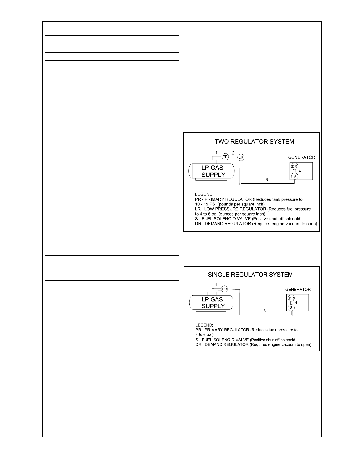
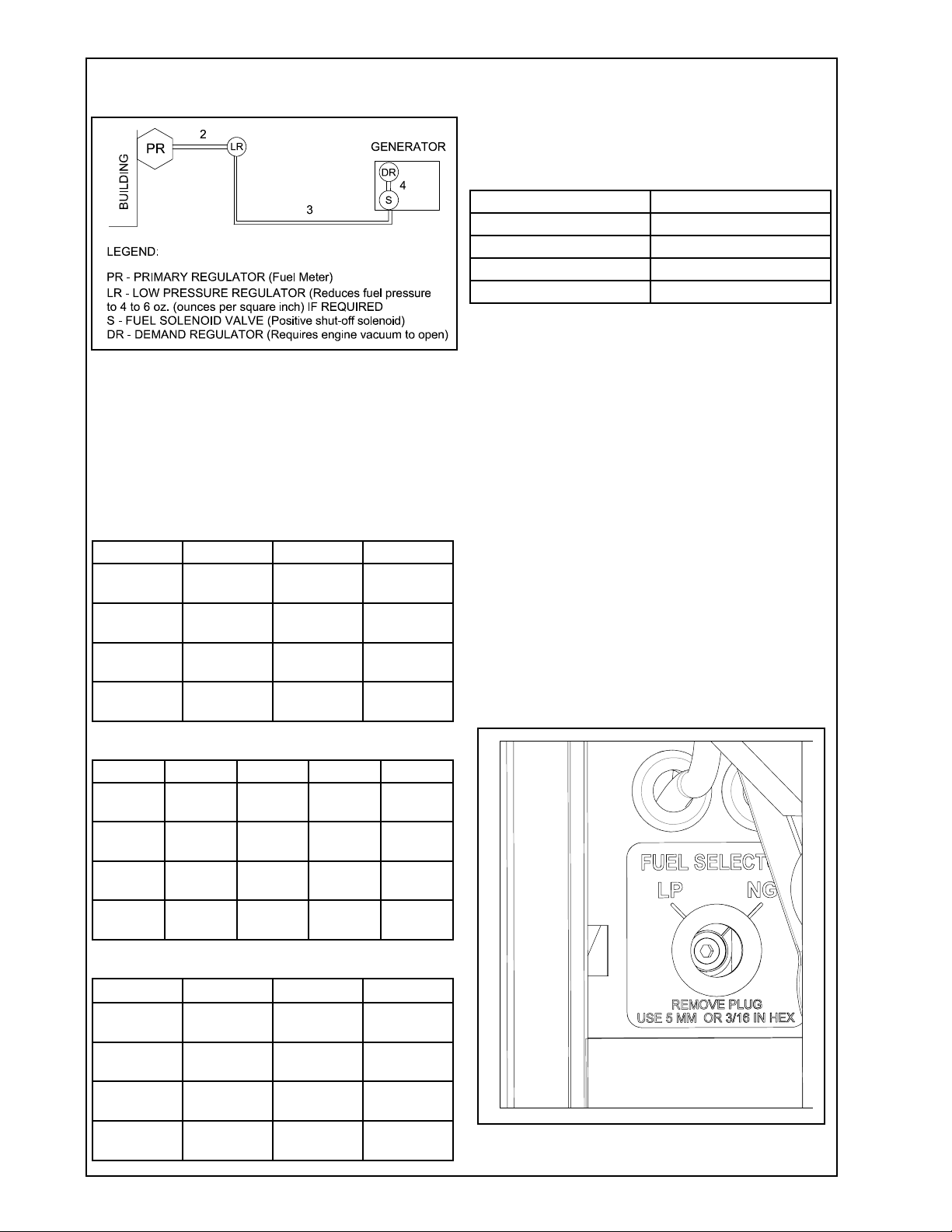
LIQUID PROPANE VAPOR (LP)
Refer to the tables on the following pages for fuel
line size and recommended tank size. For distances
of 100 feet or over, a two regulator fuel system is
recommended. This is accomplished by installing a
primary regulator at the tank which will reduce the
tank pressure down to 10 to 15 lbs.
A low pressure regulator is installed to further reduce
the fuel pressure to the required four (4) to six (6) oz.
operating pressure. This low pressure regulator
must be at least 10 feet from the engine gen-
erator set; any closer installation will require a
larger line be installed to provide a fuel reservoir.
This is also true for the single low pressure regula-
tor, it should also be a minimum of 10 feet from the
unit. If this is not done, the demand regulator on the
unit and the pressure regulator in the fuel line will
interfere with each other. When the two (2) regula-
tor system is used on LP, a fuel line size of 1/2 to 5/8
inch is generally adequate for distances up to 300
feet from the primary to the low pressure regula-
tor. (Consult you local fuel supplier for your exact
requirements). The appropriate line size from the
table below is then installed from the low pressure
regulator to the generator set.
7
12270-00 60706-229
FUEL PRESSURE
LP & NG VAPOR FUEL Correct fuel pressure can-
not be stressed enough. The most common cause
for inoperative systems is an inadequate or incor-
rect fuel pressure. Performance of the engine is in
direct relation to the correctness of the fuel system.
Shown below is a diagram of a typical LP vapor fuel
installation. Notice the following tables give two
(2) different units of measuring fuel pressure. The
first and most accurate is the use of a simple water
manometer. A manometer is calibrated in inches of
water column. The second is with a pressure gauge
calibrated in ounces per square inch.
Reference numbers 1 through 3 in the diagrams
above are system parts supplied by the customer.
Reference number 4 is on the generator.
FEET SIZE OF PIPE
up to 25 FT* 3/4 “ Pipe
25 - 100 FT* 1” Pipe
over 100 FT* Use a two regulator
system.
* Allow an additional 3 feet for each standard
elbow. Do not use ‘street ells’ (restrictive).
NATURAL GAS (NG)
The primary regulator (fuel meter) on the building
should deliver the correct volume and pressure to
the generator set. This regulator must be sized to
deliver the required BTU’s to the generator set and
all other appliances in the building. If the primary
regulator (fuel meter) is a high pressure regu-
lator, then a low pressure regulator must be
installed to bring the pressure down to 4-6 oz.
(7-11 inches water column) of pressure. This low
pressure regulator must be at least 10 feet from
the engine generator set; any closer installation
will require a larger line be installed to provide a
fuel reservoir. If this is not done, the demand regu-
lator on the unit and the pressure regulator in the
fuel line will interfere with each other. This regulator
must be sized to accommodate the demand of the
generator set and any other appliance connected to
it. See table below for the correct size of pipe to be
installed.
FEET SIZE OF PIPE
up to 25 FT* 3/4 “ Pipe
25 - 100 FT* 1” Pipe
over 100 FT* Consult Factory
* Allow an additional 3 feet for each standard
elbow. Do not use ‘street ells’ (restrictive).
******************
***** WARNING *****
******************
PERSONAL DANGER - Do not use galvanized pipe
in fuel line runs. The galvanized coating can be-
come eroded and flake off, causing possible obstruc-
tions in the regulator or fuel valve. The results could
range from inoperative engine to hazardous fuel
leaks.
**** CAUTION ****
Be careful when sealing gas joints. Excessive seal-
ing compound can be drawn into the solenoid, regu-
lator or carburetor causing an engine malfunction.
12270-00 860706-229
Shown below is a diagram of a natural gas (NG)
installation.
Reference numbers 2 through 4 in the diagram
above are system parts supplied by the customer.
Reference number 4 is on the generator.
Below are tables of the fuel pressure readings at
each reference in the system.
FUEL PRESSURE TABLES
Single Low Pressure Regulator (LP Vapor only)
REF # 1 3 4
UNIT OFF LINE PSI 7-11 IN
4-6 OZ
7-11 IN
4-6 OZ
STARTING LINE PSI 7-11 IN
4-6 OZ
7-11 IN
4-6 OZ
NO LOAD LINE PSI 7-11 IN
4-6 OZ
7-11 IN
4-6 OZ
FULL
LOAD
LINE PSI 7-11 IN
4-6 OZ
7-11 IN
4-6 OZ
Two (2) Regulator System (LP Vapor only)
REF # 1 2 3 4
UNIT
OFF
LINE PSI 10-15
LBS
7-11 IN
4-6 OZ
7-11 IN
4-6 OZ
START-
ING
LINE PSI 10-15
LBS
7-11 IN
4-6 OZ
7-11 IN
4-6 OZ
NO
LOAD
LINE PSI 10-15
LBS
7-11 IN
4-6 OZ
7-11 IN
4-6 OZ
FULL
LOAD
LINE PSI 10-15
LBS
7-11 IN
4-6 OZ
7-11 IN
4-6 OZ
Natural Gas
REF # 2 3 4
UNIT OFF 2 PSI 7-11 IN
4-6 OZ
7-11 IN
4-6 OZ
STARTING 2 PSI 7-11 IN
4-6 OZ
7-11 IN
4-6 OZ
NO LOAD 2 PSI 7-11 IN
4-6 OZ
7-11 IN
4-6 OZ
FULL
LOAD
2 PSI 7-11 IN
4-6 OZ
7-11 IN
4-6 OZ
LP TANK SIZING
Required LP tank size for LP Vapor withdrawal
operating at various outside temperatures given in
degrees Fahrenheit (Celsius).
TANK TEMPERATURE TANK SIZE
60° F (16° C) 150 GALLON
32° F (0° C) 250 GALLON
0° F (18° C) 500 GALLON
-20° F (-29° C) 1000 GALLON
NG/LP FUEL CONVERSION
These generator sets are factory tested on Natural
Gas and will require no modifications for normal
operation on Natural Gas. The carburetion system
has been preset and anti-tamper plugs have been
installed in the carburetor as required by the EPA.
To make a fuel conversion you will have to first
remove the left side door. Looking down to your left
you will see a decal and a plug. Remove the plastic
plug with a screwdriver. Using a 5mm or 3/16” hex
allen wrench turn LEFT about 1/4 turn until you feel
a click and it will stop turning.
No other modifications to the unit are necessary. To
switch from LP to NG you turn the selector to the
right (NG) position.
9
12270-00 60706-229
INSTALLING THE BATTERY
**** CAUTION ****
In the following battery installation procedure, check
to be sure the selector switch remains in the “off”
position. This should be your last step before initial
start-up.
A customer supplied twelve-volt battery is required to
complete the installation. Installation of the high-
est CCA rated battery, within the correct BCI group
(size), will increase cold weather starting perfor-
mance. Gel batteries should not be used with the
battery tender installed in the generator enclosure.
Model Voltage BCI Group MINIMUM
CCA Rating
ULPSS20B2W 12 26 500
Installation and servicing of batteries must be
performed or supervised only by personnel knowl-
edgeable of batteries and the required precautions.
Keep unauthorized personnel away from batteries.
When installing or replacing batteries, use the proper
group/size starting battery. The battery should be
a Maintenance Free lead acid design. Deep cycle
batteries will not work for this application.
CAUTION - PERSONAL DANGER
CAUTION - NEVER dispose of a battery in a fire.
The battery is capable of exploding.
CAUTION - DO NOT open or mutilate the battery.
Released electrolyte is known to be harmful to the
skin and eyes and to be very toxic.
These generator sets are all NEGATIVE ground. Be
very careful not to connect the battery in reverse
polarity, as this may short circuit the battery charging
system on the engine.
CAUTION - A battery presents a risk of electrical
shock and high short circuit current. The following
precautions must be observed when working with
batteries.
1. Remove watches, rings and other metal objects.
2. Use tools with insulated handles.
3. Check both the battery cable ends and the bat-
tery posts to be sure they are free of corrosion.
4. Always connect the battery positive cable first
and then connect the battery negative cable.
When removing the battery cables from the bat-
tery, reverse the procedure and disconnect the
negative cable first and then the positive cable.
5. Be sure all connections are tight and coat the
terminals and cable ends with dielectric grease.
WARNING - The electrolyte is a diluted sulfuric acid
that is harmful to the skin and eyes. It is electrically
conductive and corrosive. The following precautions
must always be taken.
* Always wear full eye protection and protective
clothing.
* Where electrolyte contacts the skin, wash off im-
mediately with water.
* If electrolyte contacts the eyes, flush thoroughly
and immediately with water and seek immediate
medical attention.
* Spilled electrolyte is to be washed down with an
acid neutralizing agent. A common practice is to
use a solution of one pound of bicarbonate of
soda (baking soda) to one gallon of water. The
bicarbonate of soda solution is to be added until
the evidence of reaction, foaming, has ceased.
The resulting liquid is to be flushed with water
and the area dried.
DANGER - Explosive Fire Risk
* Never smoke when near batteries.
* Do not cause a flame or spark in the battery area.
* Always discharge static electricity from your body
before touching batteries by first touching a
grounded metal surface.
SERVICING BATTERIES
Batteries used on these units may over time lose
water. This is especially true if you are using a
trickle charger to maintain your battery. When refill-
ing the battery with water, use only distilled water.
Tap water will shorten the service life of the battery.
Never fill the battery above the fill line. Over filling
above the upper level line may cause the electrolyte
to overflow, resulting in corrosion to the engine or
nearby parts. Immediately wash off any spilled elec-
trolyte following the procedure above.
BATTERY CHARGING
Units equipped with electric start have a small fly-
wheel charger built into the engine flywheel assem-
bly for recharging the starting battery. This flywheel
charger generates a small AC current that passes
through a rectifier/regulator assembly on the engine
to produce a DC charging current. This circuit is not
designed to be used as a battery charging circuit to
recharge dead batteries.
12270-00 10 60706-229
11
12270-00 60706-229
**** CAUTION ****
EQUIPMENT DAMAGE - Always connect the posi-
tive cable first and the negative cable last. When
disconnecting, remove the negative cable first and
the positive cable last. Failure to connect and dis-
connect in the proper sequence can cause equip-
ment damage.
Observe polarities: connect the positive (+) battery
terminal to the (+) cable from the engine starter;
the negative (-) battery terminal is connected to the
negative cable (ground) from the engine generator
assembly. All connections must be clean and tight.
Check the electrolyte (fluid) in the battery periodi-
cally to be sure it is above the plates. Never allow
the battery to remain in a discharged condition.
**** CAUTION ****
EQUIPMENT DAMAGE - NEVER JUMP START
these units. Doing so will destroy the engine control
module, rendering the unit non-operational. Remove
and fully recharge the battery before attempting to
start.
CONNECTING THE BATTERY CHARGER
A two-stage battery tender is provided on all PSS
series generators. This battery tender charges at
a rate of 750 mA until the battery is fully charged
and then automatically switches to a 13.2 VDC float
charger. The charger has an indicator light on it.
Red indicates it is charging, and green indicates it
is in the storage mode (float charge). This charger
is mounted on the generator set which is located
behind an access cover in the rear of the unit.
The battery tender receptacle is to be powered by
a GFCI circuit and installed in accordance with the
United States National Electric Code. These AC
wires can be run in the same conduit as the other
AC leads from the generator. It is suggested that
this circuit be fused for 15 amps. Terminal block
connections have been provided in the customer
connection area of the engine generator set. See
Page 10 for diagram.
** NOTICE **
The battery tender is not intended to recharge a
battery which has become completely discharged. It
is designed to produce enough current to recharge
a slightly low battery and maintain a fully charged
battery.
MOUNTING THE AUTOMATIC
TRANSFER SWITCH (ATS)
******************
***** WARNING *****
******************
EQUIPMENT DAMAGE - Protect the switch from
construction grit and metal chips to prevent mal-
function or shortened life of the switch. Contactors
returned for warranty consideration with foreign
materials inside of them will not be warranted.
Before installing the ATS you must first ensure that
the transfer switch is large enough to handle your
complete distribution panel. If you are installing a
100 amp transfer switch, the main line circuit breaker
must not be larger than 100 amps. If you have a
125, 150, 200 amp or larger system and want to use
a 100 amp transfer switch, you will not be able to
transfer the complete electrical system. In this case
it will be necessary to install a secondary emergency
distribution panel.
AC ELECTRICAL
CONNECTIONS
NOTICE - CLASS 1 WIRING METHODS ARE TO
BE USED FOR ALL FIELD WIRING CONNEC-
TIONS TO TERMINALS OF A CLASS 2 CIRCUIT.
******************
***** WARNING *****
******************
A main line circuit breaker has been provided inside
the generator housing. During all wiring installation,
make sure the breaker is in the off position and the
generator operators switch is in the off position.
Note: This symbol always indicates
ground where used.
GENERATOR CONNECTIONS
Minimum conductor sizes between the generator
and the ATS. Based on wire type and temperature
rating. Wire has been derated for 40° C ambient
temperatures.
12270-00 12 60706-229
The ground leads from all locations are connected to
the grounded terminal lugs also located on the side
wall. This set of terminals is labeled “GROUND”.
INSTALLATION NOTES
The load current carrying wires (L) and (T) must be
sized to handle the maximum load current without
excessive voltage drop. By code, the wire must be
heavy enough to handle the full current rating of the
main line circuit breaker (or fuse) in the entrance (or
sub-panel) protecting the contactor switch.
All wires should be installed in rigid or flexible con-
duit. Because of the many different types of service,
feeder, and distribution equipment, no specific wiring
instructions can be provided. It is, however, recom-
mended that copper wire be used. In all cases it is
essential that while the load is connected to the gen-
erator, there can be absolutely no feedback from the
generator to the power line or the power line to the
generator. When properly installed, the normal ATS
control and safety systems will eliminate all paths for
feedback. Check with your local electrical inspector
on applicable local, state and federal codes.
******************
***** WARNING *****
******************
A service disconnect must be installed in front of the
ATS panel as the ATS is not service entrance rated.
This will allow you to test the generator under load.
Should you ever have to work on the switch, you will
be able to disconnect the power and work on the
switch cold without having the power company pull
your meter.
To wire the automatic transfer switch into the exist-
ing wiring, first determine which circuits will be on
the emergency load circuit. If the entire load is to
be transferred, the transfer switch can be wired in
directly after the watt-hour meter and the service en-
trance, providing the service entrance ampere rating
is within the transfer switch’s rated capability.
If only specific circuits are to be powered under
emergency power failure conditions, an additional
distribution panel designated “emergency distribution
panel” must be installed.
All selected emergency circuits are removed from
main distribution panels and reinstalled in the emer-
gency distribution panel. Suggested circuits: freez-
er, refrigerator, furnace, emergency lights, sump
pump, emergency outlet circuits, etc. Total running
load must not exceed generator rating.
WIRE TEMPERATURE RATING
CU Connector AL Connector
75° C # 2 AWG # 1/0 AWG
90° C # 3 AWG # 2 AWG
To gain access to the customer connections, remove
the end door panel opposite the muffler. All AC and
DC connections to the ATS, 120 Volt power connec-
tion for battery charger, and battery installation are
made behind this panel. See pages 22 and 23 for
generator set and pad layout.
Two (2) hot leads, one (1) neutral and (1) ground
lead are required between the generator and the
ATS or distribution panel. The two power leads from
the generator are marked G1 and G3. Next install
two leads, one neutral and one ground, from the
generator set to the ATS or distribution panel.
In addition to the power leads, install a three wire
120 volt, 15 amp circuit from your distribution panel
to the generator. This circuit will be used to power
the battery charger, optional block heater and op-
tional battery heater.
The last two wires you will install are the DC control
leads (14 or 16 gauge) for the start circuit in the ATS.
These connections will be discussed later in more
detail.
WINCO UL ATS (ASCO 185)
See the ASCO installation manual for additional
details on proper wiring of the Automatic Trans-
fer Switch.
The standby generator terminals in the ATS are
marked “ALTERNATE L2 & L6”. The “hot” leads
G1 and G3 from the generator are connected to the
terminals L2 & L6.
The normal line power terminals in the ATS are
marked “PREFERRED - L1 & L5”. The “hot” line
power leads are L1 and L3 from the utility power
supply. They are connected to terminals L1 and L5.
The load terminals in the ATS are marked “LOAD
- L3 & L7”. The leads to the load distribution panel
are connected to terminals L3 & L7.
The neutral leads from all three locations are con-
nected to the isolated terminal lugs on the sidewall
of the cabinet. This terminal block is labeled “NEU-
TRAL” and the terminal lugs are mounted on red
isolation standoffs.
13
12270-00 60706-229
DC ELECTRICAL
INTERCONNECTION
**** CAUTION ****
Never run the AC and DC wiring in the same con-
duit.
ASCO 185 UL SWITCH
Your DC connection points in the ASCO 185 UL ATS
are on the terminal block on the bottom of the con-
troller in the lower left hand corner of the ATS panel.
The terminal block (TB7) is numbered 1 through
9. These terminals will accept # 22 - # 14 AWG
stranded wire. It is recommended that you use # 16
AWG for distances up to 200 feet. You need to run
two (2) wires from the engine generator set to the
transfer switch. You will be using terminals 4 and 5,
wire Start # 23 will connect to terminal # 5 and wire
Battery Negative # 1 will connect to terminal # 4.
See table and illustration below.
WIRE # PURPOSE RECOMMENDED
COLOR
# 23 Start Black
# 1 Battery Negative White
INITIAL START UP
******************
***** WARNING *****
******************
DO NOT jump start these engine generator sets.
Starting these units on a low battery of jump start-
ing them will cause damage to the engine control
module.
Use the following checklist to verify correct in-
stallaion before starting the engine:
� Engine oil.* Check level & fill as required with
proper grade/quantity.
� Unit mounting base properly bolted down.
� Clearance for service and maintenance on all
sides.
� Proper fuel line material and size.
� All fuel line connections tight.
� Fuel line protected and a moisture trap in
stalled (may be required for NG).
� LP/NG pressure OK. 4-6 oz. (7-11 in. WC).
� Battery connections clean and tight.
� Battery fully charged.
� All AC and DC wiring installed and properly
protected.
* Refer to engine owners manual for proper
levels and types.
After completing the above checklist, the engine
generator set is ready for the initial start-up test.
225 S. CORDOVA AVE.
LECENTER, MN 56057
507-357-6821
SERVICE DEPT.
507-357-6831
12270-00 14 60706-229
DSE 3110 CONTROL
STOP/RESET (Red Button) This button places the module into its “Stop/
Reset” mode. This will clear any alarm conditions for which the triggering
criteria have been removed. The fuel supply de-energizes and the engine
comes to a standstill. Should a remote start signal be present while operating
in this mode, a remote start WILL NOT occur.
AUTO (White Button) This button places the module into its “Automatic”
mode. This mode allows the module to control the function of the generator
automatically. The module will monitor the remote start input and once a start
request is made, the set will be automatically started and placed on load. The
module will then wait until the next start event.
START (Green button)
Pressing this button from STOP/RESET will start the engine and run off load.
PAGE
Pressing this button scrolls the display to show the various instruments.
15
12270-00 60706-229
START UP PROCEDURE
Engine Generator Set only
The engine control module (ECM) is manufactured
by Deep Sea Electronics. Model 3110 is used on
this engine generator set. See picture below. Ad-
ditional information on the DSE 3110 is on pages 14,
19-21.
Manual Operation
Press and release the red Stop/Reset button. Then
press and release the green Start Engine button.
The engine generator will crank and start automati-
cally. If the engine fails to start see Fault Codes on
page 20 to correct the problem before proceeding.
With the engine running smoothly, check the no load
voltage and frequency at wire # 1 and # 4 (L2 and
L6 in the ASCO ATS) on the generator terminal block
in the ATS. The voltage should be 240 volts plus or
minus nominal. The frequency should be between
61.5 to 62 hertz (Hz). The voltage should also be
checked between the hot terminals (L2 and L6) and
the neutral to be certain of a balanced voltage output
and a solid neutral connection. The voltage should
be about one half of the line to line voltage. See
picture below for frequency adjustments.
** NOTICE **
If for any reason during the check out procedures
the voltage and frequency are not correct, press the
red Stop/Reset button and correct the trouble before
proceeding.
After verifying the voltage and frequency are correct,
press the Stop/Reset button. This will shut off the
engine immediately.
BEND THIS TAB TO CHANGE THE ENGINE SPEED (FREQUENCY).
STRETCHING SPRING INCREASES THE FREQUENCY (INCREASES ENGINE
SPEED).
RELAXING SPRING DECREASES THE FREQUENCY (DECREASES ENGINE SPEED).
12270-00 16 60706-229
Transfer Switch & Engine Generator
Automatic (remote) Operation
This procedure checks the electrical operation of
the automatic transfer switch. If the actual operation
does not follow this procedure, consult the trouble-
shooting section in the transfer switch manual.
1. Turn on the preferred source (utility) circuit
breaker. The Utility Acceptable Light should now
come on, as well as the Load On Utility Light. If
these lights fail to come on, recheck your incoming
power to insure you have 240 volts nominal. If not,
troubleshoot your utility source before continuing.
2. Press and release the Auto button on the
engine control module (ECM). The auto mode icon
will appear on the screen. The unit is now ready to
be operated from the Automatic Transfer Switch.
3. Turn on the alternate source (generator) circuit
breaker.
******************
***** WARNING *****
******************
PERSONAL INJURY HAZARD - Install front cover
in transfer switch before operation. An electrical sys-
tem fault could cause a flash and severe personal
injury.
DESCRIPTION
The digital controller provides sensing, timing, and
control functions for the ATS. This micro-processor-
based controller includes built-in control buttons and
status lights for control of the ATS and the generator.
PUSH BUTTONS
On the front control display are three push buttons
that control the operation of the generator and the
ATS.
**** CAUTION ****
Before using the transfer test button, be sure
that conditions are safe for running the genera-
tor and for load transfer
TRANSFER TEST Use this button to test the
system. This operation starts the generator and
transfers the load. The controller is shipped with a
load transfer set by default. Changing the exercise
without a load will be discussed later. Be sure that
conditions are safe to do this operation.
BYPASS TIME DELAY Use this button to cancel
the active time delay or exercise period (stops the
generator after cooldown).
SET ENGINE EXERCISER Use this button to set
the automatic exerciser.
INDICATOR LIGHTS
On the front control display are five lights that indi-
cate the status of the sources and the ATS.
UTILITY ACCEPTABLE This light indicates that
the utility voltage is acceptable for connection to the
load.
GENERATOR ACCEPTABLE This light indicates
that the generator voltage and frequency is accept-
able for connection to the load.
LOAD ON UTILITY This light indicates that the
generator voltage is acceptable for connection to the
load.
LOAD ON GENERATOR This light indicates that
the generator voltage and frequency is acceptable
for connection to the load.
ASCO 185 DIGITAL CONTROLLER
17
12270-00 60706-229
AUTOMATIC GENERATOR EXERCISER
This light indicates the status of the generator exer-
ciser:
- Blinks during the exercise period (including cool
down).
- stays on when the exerciser has been set.
- is off when the exerciser has not been set.
GENERATOR STARTING CONTACTS
Disconnect the generator battery. Connect the
generator starting wires # 1 (battery -) to terminal 4
and wire # 23 (start) to terminal 5 of the TB7 terminal
block. This is removable for convenient connections.
GENERATOR EXERCISER CIRCUIT
The automatic generator exerciser is configured to
automatically exercise the generator for 20 minutes
once every week.
In order to set and test the exercise circuit the
AUTO button on the generator control panel
must be on.
EXERCISE WITH OR WITHOUT LOAD
The transfer switch can be set up to exercise the
generator with or without a load transfer. Normally
Winco generators exercise without a load transfer.
This is because you may not wish to have a mo-
mentary interruption of power. Turn the exerciser
dipswitch on. Then set the “with load” or “without
load” dipswitch. See table below.
Function Factory
Setting
DIP
Switch
DIP
Actuator
Actuator
Position
clock battery off S2 10 on (up)
off (down)
exerciser off S1 7 on (up)
off (down)
with load or
without load
without
load
S1 8 with (up)
without
(down)
SETTING THE EXERCISER CIRCUIT
Press and hold (5 seconds) the Set Engine Exer-
ciser button. The exercise period occurs immedi-
ately and at the same time weekly thereafter. The
status light below the button blinks during the exer-
cise period (including the cooldown). The light stays
on to indicate that the exerciser has been set. If the
light is off, the exerciser has not been set.
CANCELLING AN ACTIVE EXERCISE PERIOD
Press the Bypass Time Delay button to stop an
exercising generator. If exercise with load is set, the
ATS retransfers the load to the utility, then stops the
generator after cooldown.
******************
***** WARNING *****
******************
WITH A TOTAL POWER FAILURE (UTILITY
POWER FAILS AND THE GENERATOR FAILS TO
START AND RUN) THE EXERCISER MUST BE
RESET AFTER THE POWER IS RESTORED.
SETTINGS
The ASCO 185 has settings that can be changed
for various applications. The dipswitch options are
explained in the ASCO 185 Operator’s Manual.
SEE THE FOLLOWING PAGE FOR SEQUENCE
OF OPERATION.
This completes your installation and unit testing.
ALWAYS leave the system in automatic mode unless
servicing the unit. For automatic operation, the auto
mode icon must be displayed on the engine control
module display.
12270-00 18 60706-229
19
12270-00 60706-229
FRONT PANEL CONFIGURATION
1
2
3
4
This configuration mode allows the operator limited customizing of the way the module
operates. Use the module’s navigation buttons to traverse the menu and make value
changes to the parameters.
1. ACCEPT button. 2. NEXT PAGE button.
3. DECREASE VALUE / NEXT ITEM 4. INCREASE VALUE / NEXT ITEM
ACCESSING THE FRONT PANEL
Press 1 (accept) and 2 (next page) simultaneously (at the same time). This display
shows the configuration icon: The first parameter is also displayed.
EDITING A PARAMETER
Enter the editor as described above.
* Press 2 to select the required ‘page’ as detailed below.
* Press 4 to select the next parameter or 3 to select the previous parameter within the
current page.
* When viewing the parameter to be changed, press the 1 button. The value begins to
flash.
* Press 4 or 3 to adjust the value to the requested setting.
* Press 1 to save the current value. The value stops flashing.
* Press and hold the 1 button to exit the editor, the configuration icon is removed
from the display.
NOTE: Values representing pressure will be displayed in Bar. Values representing tem-
perature are displayed in degrees Celsius.
NOTE: When adjusting values in the front panel editor, a “press and hold” of the incre-
ment button will cover the full range of the item being adjusted (min to max) in under 20
seconds.
NOTE: When the editor is visible, it is exited after 5 minutes of inactivity for security.
1. ACCEPT button. 2. NEXT PAGE button.
12270-00 20 60706-229
DSE 3110 CONTROL
FAULT CODES
DESCRIPTION
AUXILIARY INPUTS Auxiliary inputs can be user configured and will display
the message as written by the user.
FAIL TO START The engine has not fired after the preset number of start
attempts.
FAIL TO STOP
The module has detected a condition that indicates that
the engine is running when it has been instructed to stop.
NOTE:- ‘Fail to Stop’could indicate a faulty oil pressure sensor
- If engine is at rest, check oil sensor wiring and configuration.
LOW OIL PRESSURE
The module detects that the engine oil pressure has fallen
below the low oil pressure pre-alarm setting level after the
Safety On timer has expired.
ENGINE HIGH OIL
TEMPERATURE
The module detects that the engine oil temperature has
exceeded the high engine temperature pre-alarm setting
level after the Safety On timer has expired.
UNDERSPEED The engine speed has fallen below the underspeed pre
alarm setting
OVERSPEED The engine speed has risen above the overspeed pre
alarm setting
BATTERY UNDER
VOLTAGE / BATTERY
OVER VOLTAGE
The DC supply has fallen below or risen above the low/
high volts setting level.
GENERATOR UNDER
VOLTAGE
The generator output voltage has fallen below the pre-set
pre-alarm setting after the Safety On timer has expired.
GENERATOR OVER
VOLTAGE
The generator output voltage has risen above the pre-set
pre-alarm setting.
GENERATOR UNDER
FREQUENCY
The generator output frequency has fallen below the
pre-set pre-alarm setting after the Safety On timer has
expired.
GENERATOR OVER
FREQUENCY
The generator output frequency has risen above the pre-
set pre-alarm setting.
C
D

Other Winco Inverter manuals

Winco DP7500/A Setup guide

Winco

Winco DP7500/A Setup guide

Winco W6000HE-03/A Administrator Guide

Winco

Winco W6000HE-03/A Administrator Guide

Winco DR20I4-/1 Series Setup guide

Winco

Winco DR20I4-/1 Series Setup guide

Winco WL22000VE/A Setup guide

Winco

Winco WL22000VE/A Setup guide

Winco W3000H/C Setup guide

Winco

Winco W3000H/C Setup guide

Winco WL12000HE-03/A Administrator Guide

Winco

Winco WL12000HE-03/A Administrator Guide

Winco TB4000 User manual

Winco

Winco TB4000 User manual

Winco DP3000/T Setup guide

Winco

Winco DP3000/T Setup guide

Winco PSS21F4/1 Setup guide

Winco

Winco PSS21F4/1 Setup guide

Winco PTO series User manual

Winco

Winco PTO series User manual

Winco PSS12H2W Setup guide

Winco

Winco PSS12H2W Setup guide

Winco W6010DI Setup guide

Winco

Winco W6010DI Setup guide

Winco PSS8000 Setup guide

Winco

Winco PSS8000 Setup guide

Winco PSS30/B User manual

Winco

Winco PSS30/B User manual

Winco WC6000HE/F Setup guide

Winco

Winco WC6000HE/F Setup guide

Winco Home power HPS12000HE Setup guide

Winco

Winco Home power HPS12000HE Setup guide

Winco Home power HPS12000HE Setup guide

Winco

Winco Home power HPS12000HE Setup guide

Winco PSS30/F Setup guide

Winco

Winco PSS30/F Setup guide

Winco HPS6000HE/I Setup guide

Winco

Winco HPS6000HE/I Setup guide

Winco WL12000HE/K Setup guide

Winco

Winco WL12000HE/K Setup guide

Winco W15PTOS/E Assembly instructions

Winco

Winco W15PTOS/E Assembly instructions

Winco WL18000VE-03/A Administrator Guide

Winco

Winco WL18000VE-03/A Administrator Guide

Winco DR2014 Setup guide

Winco

Winco DR2014 Setup guide

Winco W10000VE/A Setup guide

Winco

Winco W10000VE/A Setup guide

Popular Inverter manuals by other brands

Senci SC2000i operating manual

Senci

Senci SC2000i operating manual

Champion CPG4000DHY-EU Operator's manual

Champion

Champion CPG4000DHY-EU Operator's manual

VOLTA V-385 instruction manual

VOLTA

VOLTA V-385 instruction manual

MAKINEX GEN-6P Operator's manual

MAKINEX

MAKINEX GEN-6P Operator's manual

Energenie EG-PWC-004 user manual

Energenie

Energenie EG-PWC-004 user manual

Lennox e-Lite LV-MO200 Installation and operation manual

Lennox

Lennox e-Lite LV-MO200 Installation and operation manual

Dometic GROUP WAECO PocketPower TSI102 operating manual

Dometic GROUP

Dometic GROUP WAECO PocketPower TSI102 operating manual

SolarEdge SE5000H-AU installation guide

SolarEdge

SolarEdge SE5000H-AU installation guide

PowMr POW-LVM3K-24V-H user manual

PowMr

PowMr POW-LVM3K-24V-H user manual

VIPool 50963 (E) manual

VIPool

VIPool 50963 (E) manual

Kaco Powador 30.0-72.0 TL3 manual

Kaco

Kaco Powador 30.0-72.0 TL3 manual

CEA PROJECT 1300 Operator's manual

CEA

CEA PROJECT 1300 Operator's manual

Daikin B-Series Service manual

Daikin

Daikin B-Series Service manual

VOLTWORKS VS-4000QBR user manual

VOLTWORKS

VOLTWORKS VS-4000QBR user manual

SG GROUP 3200W E.START instructions

SG GROUP

SG GROUP 3200W E.START instructions

INVT Goodrive 35 Series Operation manual

INVT

INVT Goodrive 35 Series Operation manual

FUELCELL H-1000 user manual

FUELCELL

FUELCELL H-1000 user manual

Hopewind hopeSun Series Quick installation guide

Hopewind

Hopewind hopeSun Series Quick installation guide

manuals.online logo
manuals.online logoBrands
  • About & Mission
  • Contact us
  • Privacy Policy
  • Terms and Conditions

Copyright 2025 Manuals.Online. All Rights Reserved.