Simply Brands MS-PH68-SS User manual
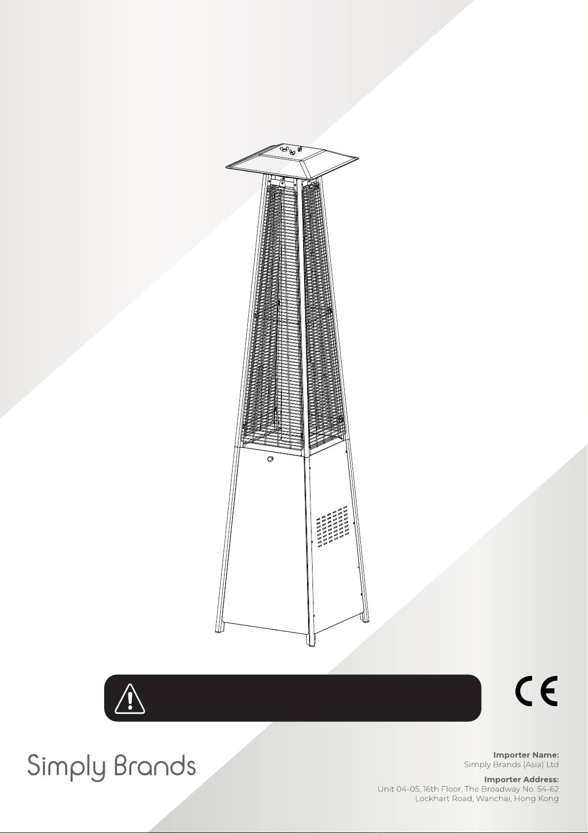
PYRAMID GAS
PATIO HEATER
Instruction Manual
Keep the instructions for future reference
PPYYRRAAMMIIDDGGAASSPPAATTIIOOHHEEAATTEERR
IINNSSTTRRUUCCTTIIOONNMMAANNUUAALL
2527-21
Keep the instructions for future reference
PPYYRRAAMMIIDDGGAASSPPAATTIIOOHHEEAATTEERR
IINNSSTTRRUUCCTTIIOONNMMAANNUUAALL
2527-21
2575-21
IMPORTANT: Keep the instructions for future reference
Model Number: MS-PH68-SS
www.simply-brands.com
Pyramid Gas Patio Heater_IM_Wowcher_A4.indd 1Pyramid Gas Patio Heater_IM_Wowcher_A4.indd 1 12/05/2021 13:1512/05/2021 13:15
2
FOR YOUR SAFETY
If you smell gas:
1. Shut off the gas supply to the appliance.
2. Extinguishanyvisibleames.
3. If smoke odour continues, immediately phone your gas
supplierortheemergencyreservice.
WARNlNG SAFETY RULES
PLEASE READ THE FOLLOWING
SAFETY RULES PRlOR TO OPERATING
THE PATIO GAS HEATER
FOR YOUR SAFETY
1. Donotstoreorusegasolineorotherammablevapours
and liquids in the vicinity of this or any other appliance
2. An LP cylinder not connected for use shall not be stored in
the vicinity of this or any other appliance
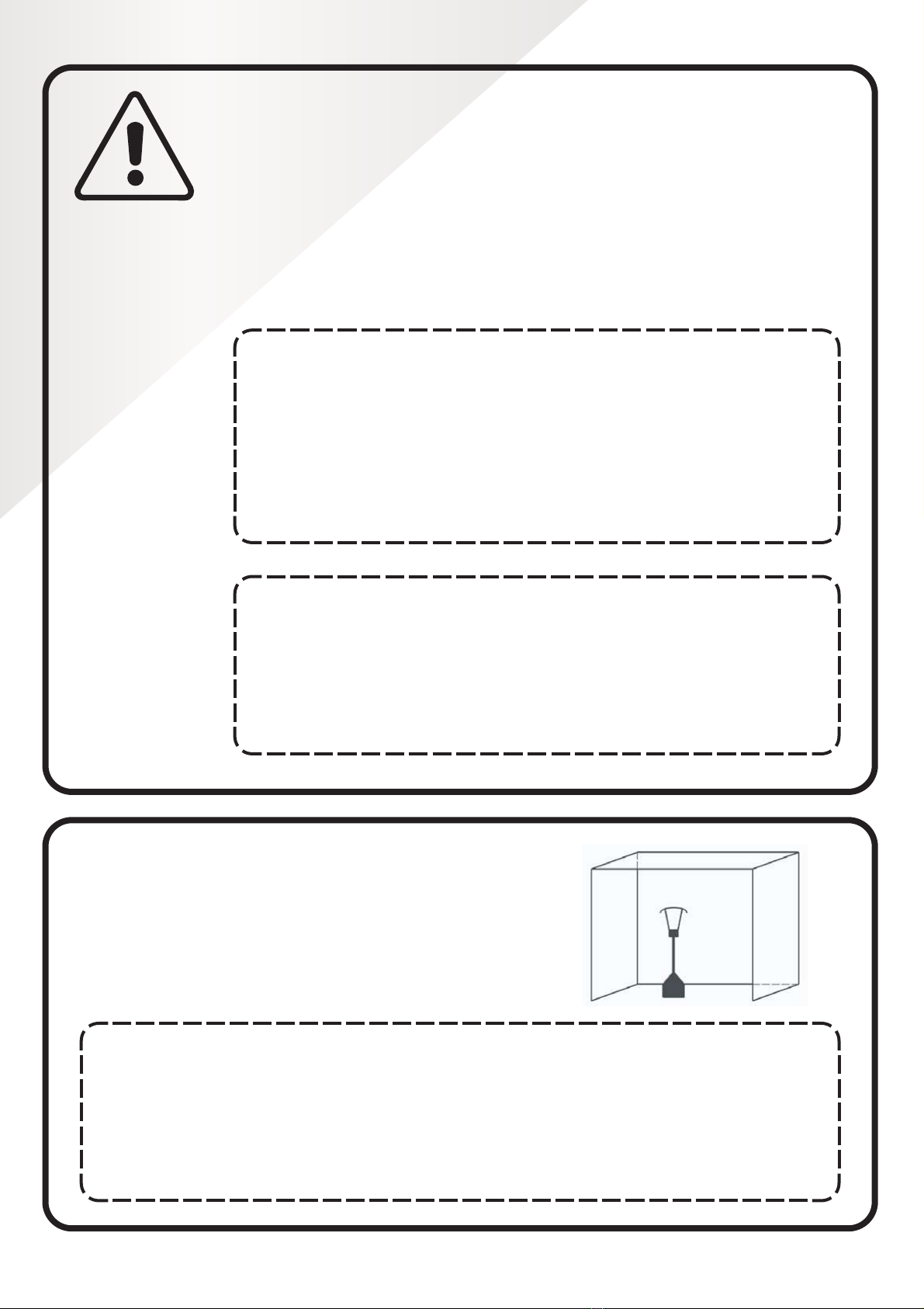
PLACEMENT WARNlNG
1. For use outdoors or in amply ventilated areas.
2. An amply ventilated area must have a minimum
of 25 % of the surface area open.
3. The surface area is the sum of the walls surface.
WARNlNG SAFETY RULES
PLEASE READ THE FOLLOWING SAFETY RULES PRlOR
TO OPERATION OF THE HEATER
FOR YOUR SAFETY
If you smell gas:
1Shut off gas to the appliance.
2Extinguish any open flame.
3If odor continues, immediately call your gas supplier or your fire
Department.
FOR YOUR SAFETY
1. Do not store or use gasoline or other flammable vapors
and liquids in the vicinity of this or any other appliance
2. An LP cylinder not connected for use shall not be stored in the
vicinity of this or any other appliance
WARNlNG
1) For use outdoors or in amply ventilated areas.
2) An amply ventilated area must have a minimum of 25 % of the
surface area open.
3) The surface area is the sum of the walls surface.
WARNING: Improper installation, adjustment, alteration, service
or maintenance Can cause injury or property damage. Read the
installation, operating and maintenance instructions thoroughly
before installing or servicing this equipment.
INSTALLATION WARNlNG
Improper installation, adjustment, alteration, service or maintenance can
cause injury or property damage. Read the installation, operating and
maintenance instructions thoroughly before installing, operating or servicing
this equipment.
Pyramid Gas Patio Heater_IM_Wowcher_A4.indd 2Pyramid Gas Patio Heater_IM_Wowcher_A4.indd 2 12/05/2021 13:1512/05/2021 13:15

3
GAS a.k.a. ‘LPG’
CYLINDER WARNlNG
Read the instructions before installation and use.
•
This appliance must be installed and the LPG cylinder stored in accordance
with the regulations in force;
•
Do not obstruct the ventilation holes of the cylinder housing;
•
Do not move the appliance when in operation;
• Shut off the valve at the LPG cylinder or the regulator before moving the
appliance;
• Thetubingortheexiblehosemustbechangedwithintheprescribed
intervals;
•
UseonlythetypeofLPGandthetypeofcylinderspeciedbythe
manufacturer;
•
The LPG cylinder used with your patio heater must meet the following
requirements (see LPG Requirements on page 6):
Purchase LPG cylinders only with these required measurements:
31.8cm (diameter) x 58cm (tall) with 15kg maximum capacity.
•
In case of violent wind, particular attention must be taken against tilting of
the appliance.
Pyramid Gas Patio Heater_IM_Wowcher_A4.indd 3Pyramid Gas Patio Heater_IM_Wowcher_A4.indd 3 12/05/2021 13:1512/05/2021 13:15

4
TABLE OF CONTENTS
Caution ......................................................................................................5
Heater Stand and Location .............................................................6
LPG (Liqueed Petroleum Gas) Requirements....................6
Leakage Test ...........................................................................................6
Operation and Storage......................................................................7
Cleaning and Care .............................................................................. 8
Parts and Specications.................................................................. 8
Assembly Parts and Procedures ................................................10
Problems Check List.........................................................................18
Pyramid Gas Patio Heater_IM_Wowcher_A4.indd 4Pyramid Gas Patio Heater_IM_Wowcher_A4.indd 4 12/05/2021 13:1512/05/2021 13:15

5
CAUTION
PLEASE READ CAREFULLY THE FOLLOWING SAFETY GUIDELINES BEFORE OPERATION.
•
Do not use the patio heater for indoors, as it may cause personal injury or property damage.
•
This outdoor heater is not intended to be installed on recreational vehicles and/or boats.
•
Installationandrepairshouldbedonebyaqualiedserviceperson.
•
Improper installation, adjustment, alteration can cause personal injury or property damage.
•
Do not attempt to alter the unit in any manner.
•
Never replace or substitute the regulator with any regulator other than the factory-suggested replacement.
•
Donotstoreorusegasolineorotherammablevapoursorliquidsintheheaterunit.
•
The whole gas system, hose, regulator, pilot or burner should be inspected for leaks or damage before use, and at
leastannuallybyaqualiedserviceperson.
•
All leak tests should be done with a soap solution.
•
Do not use the heater until all connections have been leak tested.
•
Turn off the gas valve immediately if a smell of gas is detected. Turn the Cylinder Valve OFF. If a leak is at the Hose/
Regulator connection: tighten the connection and perform another leak test. If bubbles continue appearing, it
should be returned to the hose’s place of purchase. If a leak is at the Regulator/Cylinder Valve connection: disconnect,
reconnect, and perform another leak test. If you continue to see bubbles after several attempts, the cylinder valve is
defective and should be returned to cylinder’s place of purchase.
•
Do not transport the heater while it’s operating.
•
Do not move the heater after it has been turned off until the temperature has cooled down.
•
Keep the ventilation opening of the cylinder enclosure free and clear of debris.
•
Donotpainttheradiantscreen,controlpanelortopcanopyreector.
•
Control compartment, burner and circulation air passageways of the heater must be kept clean.
•
Frequent cleaning may be required as necessary.
•
The LPG tank should be turned off when the heater is not in use.
•
Check the heater immediately if any of the following occurs:
– The heater does not reach temperature.
– The burner makes a popping noise during use (a slight noise is normal when the burner is extinguished).
–Smellofgasinconjunctionwithextremeyellowtippingoftheburnerames.
•
The LPG regulator/hose assembly must be located out of pathways where people may trip over it or in area where the
hose will not be subject to accidental damage.
•
Any guard or other protective device removed for servicing the heater must be replaced before operating the heater.
•
Adults and children should stay away from high temperature surfaces to avoid burns or setting clothing alight.
•
Children should be carefully supervised when they are in the area of the heater.
•
Clothingorotherammablematerialsshouldnotbehungontheheaterorplacedonorneartheheater.
•
Change the gas cylinder in an amply ventilated area, away from any ignition source
(candle,cigarettesandotherameproducingappliances);
•
Please follow the diagram on the right to check and ensure that the regulator seal
iscorrectlyttedsothatit’sabletoproperlyfulllitsfunction;
•
Do not obstruct the ventilation holes of the cylinder housing;
•
Close the gas supply at the valve of the gas cylinder or the regulator after use;
•
In the event of gas leakage, the appliance shall not be used or if alight, the gas
supplyshallbeshutoffandtheapplianceshallbeinvestigatedandrectiedbefore
it is used again;
•
Check the hose at least once per month, each time the cylinder is changed or each
time before long period of non-use. If it shows signs of cracking, splitting or other
deterioration it shall be exchanged for a new hose of the same length and of the equivalent quality;
• The use of this appliance in enclosed areas can be dangerous and is PROHIBITED;
•
Read the instructions before using this appliance. The appliance must be installed in accordance with the
instructions and local regulations.
•
For hose/regulator connection, and regulator/cylinder connection, please refer to the diagram shown above.
•
This product contains small batteries. Swallowed small batteries can cause A CHOKING HAZARD. Seek immediate
medical attention if batteries are swallowed or inhaled. Keep children away from the appliance’s small batteries.
-1-
CAUTION
PLEASE READ CAREFULLY THE FOLLOWING SAFETY GUIDELINES BEFORE OPERATION.
Do not use the patio heater for indoors, as it may cause personal injury or property damage.
This outdoor heater is not intended to be installed on recreational vehicles and/or boats.
Installation and repair should be done by a qualified service person.
Improper installation, adjustment, alteration can cause personal injury or property damage.
Do not attempt to alter the unit in any manner.
Never replace or substitute the regulator with any regulator other than the factory-suggested replacement.
Do not store or use gasoline or other flammable vapors or liquids in the heater unit.
The whole gas system, hose, regulator, pilot or burner should be inspected for leaks or damage before
use, and at least annually by a qualified service person.
All leak tests should be done with a soap solution. Never use an open flame to check for leaks.
Do not use the heater until all connections have been leak tested.
Turn off the gas valve immediately if smell of gas is detected. Turn Cylinder Valve OFF. If leak is at Hose/
Regulator connection: tighten connection and perform another leak test. If bubbles continue appearing
should be returned to hose’s place of purchase. If leak is at Regulator/Cylinder Valve connection: disconnect,
reconnect, and perform another leak check. If you continue to see bubbles after several attempts, cylinder
valve is defective and should be returned to cylinder’s place of purchase.
Do not transport heater while it’s operating.
Do not move the heater after it has been turned off until the temperature has cooled down.
Keep the ventilation opening of the cylinder enclosure free and clear of debris.
Do not paint the radiant screen, control panel or top canopy reflector.
Control compartment, burner and circulation air passageways of the heater must be kept clean.
Frequent cleaning may be required as necessary.
The LP tank should be turned off when the heater is not in use.
Check the heater immediately if any of the following occurs:
- The heater does not reach temperature.
- The burner makes popping noise during use (a slight noise is normal when the burner is extinguished).
- Smell of gas in conjunction with extreme yellow tipping of the burner flames.
The LP regulator/hose assembly must be located out of pathways where people may trip over it or in
area where the hose will not be subject to accidental damage.
Any guard or other protective device removed for servicing the heater must be replaced before operating the heater.
Adults and children should stay away from high temperature surface to avoid burns or clothing ignition.
Children should be carefully supervised when they are in the area of the heater.
Clothing or other flammable materials should not be hung on the heater or placed on or near the heater.
To change the gas cylinder in a amply ventilated area, away from any ignition
source (candle, cigarettes, other flame producing appliances, ...);
To check that the regulator seal is correctly fitted and able to fulfill its function
showed as photo right;
To not obstruct the ventilation holes of the cylinder housing;
To close the gas supply at the valve of the gas cylinder or the regulator after use;
In the event of gas leakage, the appliance shall not be used or if alight, the gas supply
shall be shut off and the appliance shall be investigated and rectified before it is used again;
To check the hose at least once per month each time the cylinder is changed or each time before long time no use.
If it shows signs of cracking, splitting or other deterioration it shall be exchanged for new hose of the same length and of the
equivalent quality;
The use of this appliance in enclosed areas can be dangerous and is PROHIBITED;
Read the instructions before using this appliance. The appliance must be installed in accordance with the instructions and
local regulations.
For connection of hose and regulator,and connection of regulator and hose, please refer to photo showed above.
This product contains small batteries. Swallowed small batteries can cause CHOCKING HAZARD. Seek immediate medical
attention if batteries are swallowed or inhaled. Keep children away from the small batteries.
Hose/ Regulator connection and
Regulator / Cylinder connection
seal hose
regulater
cylinder
Hose/Regulator connection and
Regulator/Cylinder connection
Seal
Regulator
Cylinder
Hose
Pyramid Gas Patio Heater_IM_Wowcher_A4.indd 5Pyramid Gas Patio Heater_IM_Wowcher_A4.indd 5 12/05/2021 13:1512/05/2021 13:15
6
HEATER STAND AND LOCATION
•
The heater is for outdoor use only. Always ensure that adequate fresh
air ventilation is provided.
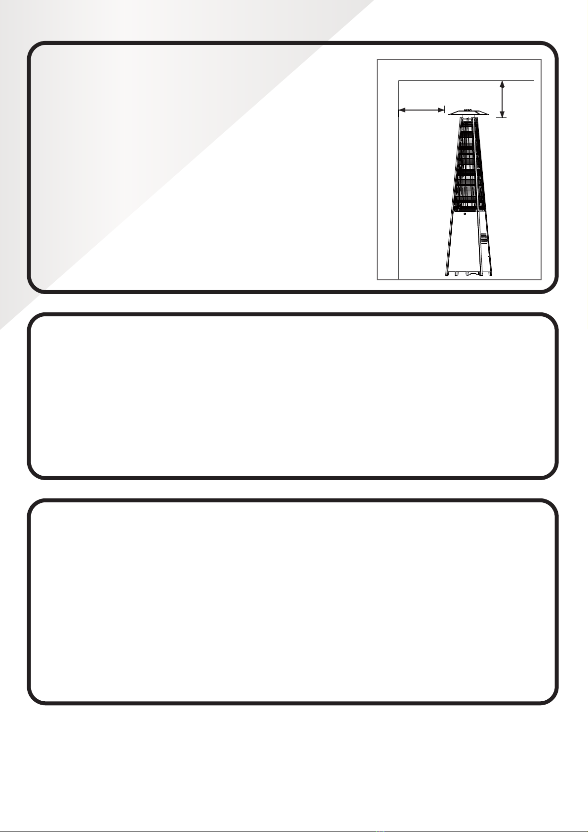
•
Always maintain proper clearance to non protected combustible
materials, i.e. minimum of 100cm away from the top and minimum of
100cm away from the sides of the heater.
• Theheatermustbeplacedonlevelrmground.
•
Never operate the heater in an explosive atmosphere like in areas
wheregasolineorotherammableliquidsorvapoursarestored.
•
To protect the heater from strong winds, anchor the base securely to
the ground with screws.
-2-
HEATER STAND AND LOCATION
The heater is primarily for outdoor use only. Always ensure that
adequate fresh air ventilation is provided.
Always maintain proper clearance to non protected combustible materials
i.e. top 100 cm and sides 100 cm minimum.
Heater must be placed on level firm ground.
Never operate heater in an explosive atmosphere like in areas where
gasoline or other flammable liquids or vapors are stored.
To protect heater from strong wind, anchor the base securely to the
ground with screws.
CEILING
WALL
100 cm
100 cm
GAS REQUIREMENTS
Use propane, butane or their mixtures gas only.
The pressure regulator and hose assembly to be used must conform to local standard codes.
The installation must conform to local codes, or in the absence of local codes, with the standard for the
storage and handling of liquid petroleum gases.
A dented, rusted or damaged tank may be hazardous and should be checked by your tank
supplier. Never use a tank with a damaged valve connection.
The tank must be arranged to provide for vapor withdrawal from the operating cylinder.
Never connect an unregulated tank to the heater.
LEAKAGE TEST
Gas connections on the heater are leak tested at the factory prior to shipment. A complete gas tightness
check must be performed at the installation site due to possible mishandling in shipment or excessive
pressure being applied to the heater.
Make a soap solution of one part liquid detergent and one part water. The soap solution can be applied
with a spray bottle, brush or rag. Soap bubbles will appear in case of a leak.
The heater must be checked with a full cylinder.
Make sure the safety control valve is in the OFF position.
Turn the gas supply ON.
In case of a leak, turn off the gas supply. Tighten any leaking fittings, then turn the gas supply on and re-
check.
Never leak test while smoking.
100cm
CEILING
WALL
100cm
LPG (
•
Use propane, butane or propane/butane mixture gas only.
• The pressure regulator and hose assembly to be used must conform to local standard codes.
•
The installation must conform to local codes, or in the absence of local codes, with the standard for the
storage and handling of liquid petroleum gases.
•
A dented, rusted or damaged tank may be hazardous and should be checked by your tank supplier. Never
use a tank with a damaged valve connection.
•
The tank must be arranged to provide for vapour withdrawal from the operating cylinder.
•
Never connect an unregulated tank to the heater.
LEAKAGE TEST
Gas connections on the heater are leak tested at the factory prior to shipment. A complete gas tightness check
must be performed at the installation site due to possible mishandling in shipment or excessive pressure being
applied to the heater.
•
Make a soap solution of one part liquid detergent and one part water. The soap solution can be applied with a
spray bottle, brush or rag. Soap bubbles will appear in case of a leak.
• The heater must be checked with a full gas cylinder.
• Make sure the safety control valve is in the OFF position.
• Turn the gas supply ON.
•
Incaseofaleak,turnoffthegassupply.Tightenanyleakingttings,thenturnthegassupplyonand
re-check.
• Never leak test while smoking.
Pyramid Gas Patio Heater_IM_Wowcher_A4.indd 6Pyramid Gas Patio Heater_IM_Wowcher_A4.indd 6 12/05/2021 13:1512/05/2021 13:15
7
OPERATION AND STORAGE
1. Turn on the valve on the gas supply cylinder completely.
2. Press and turn the variable control knob to the PILOT position (counter-clockwise 90°).
3. Press down the variable control knob and hold for 30 seconds. While holding down the variable control knob,
presstheigniterbuttonseveraltimesuntilthepilotamelights.Releasethevariablecontrolknobafterthe
pilotamelights.
Note:
•
If a new gas cylinder has just been connected, please allow at least one minute for the air in the gas
pipeline to purge out through the pilot hole.
•
Whenlightingthepilotamemakesurethatthevariablecontrolknobiscontinuouslypresseddown
whilepressingtheigniterbutton.Variablecontrolknobcanbereleasedafterthepilotamelights.
•
Ifthepilotamedoesnotlightoritgoesout,repeatstep3.
4.Afterthepilotamelights,turnthevariablecontrolknobtomaximumpositionandleaveittherefor
5 minutes or more before turning the knob to desired temperature position.
Warning: check that no broken glass is found before operation.
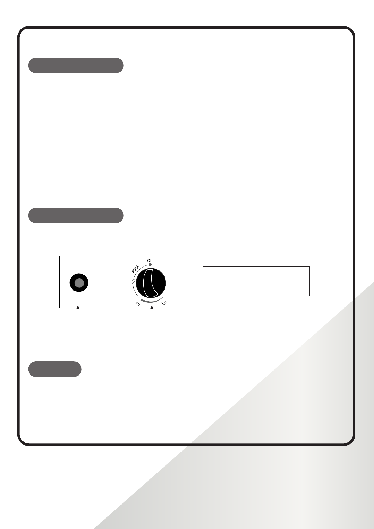
TO TURN ON THE HEATER
TO TURN OFF THE HEATER
1. Turn the variable control knob to PILOT position.
2. Press and turn the variable control knob to OFF position.
3. Turn off the valve on the gas supply cylinder completely.
Off: the heater stop work
Hi: maximum temperature position
Lo: minimum temperature position
lgniter
maximum
Warning check that no broken on the glass is found before operation.
Igniter
Off: the heater stop work
Hi: maximum temperature position
Lo: minimum temperature position
Variable control knob
regulator
Variable control knobIgniter
STORAGE
1. Always close the gas valve of the gas cylinder after use or in case of a disturbance.
2. Remove the pressure regulator and the hose.
3. Check the tightness of the gas valve and for damage. If you suspect damage, have it changed by your
gas dealer.
4. Always store a liquid gas cylinder in a location that’s well ventilated to prevent the accumulation of any
leaked gases which can cause a serious health hazard.
Pyramid Gas Patio Heater_IM_Wowcher_A4.indd 7Pyramid Gas Patio Heater_IM_Wowcher_A4.indd 7 12/05/2021 13:1512/05/2021 13:15
8
CLEANING AND CARE
•
Wipe off powder coated surfaces with a soft, moist rag. Do not clean the heater with cleaning agents that
are combustible or corrosive.
•
Remove debris from the burner to keep it clean and safe for use.
•
It’sadvisabletocovertheburnerunitwithanon-ammableprotectivecoverwhentheheaterisnotinuse.
PARTS AND SPECIFICATIONS
CLEANING AND CARE
•Wipe off powder coated surfaces with soft, moist rag. Do not clean heater with cleaners that
are combustible or corrosive.
•Remove debris from the burner to keep it clean and safe for use.
•Cover the burner unit with the optional protective cover when the heater is not in use.
PARTS AND SPECIFICATIONS
- 4 -
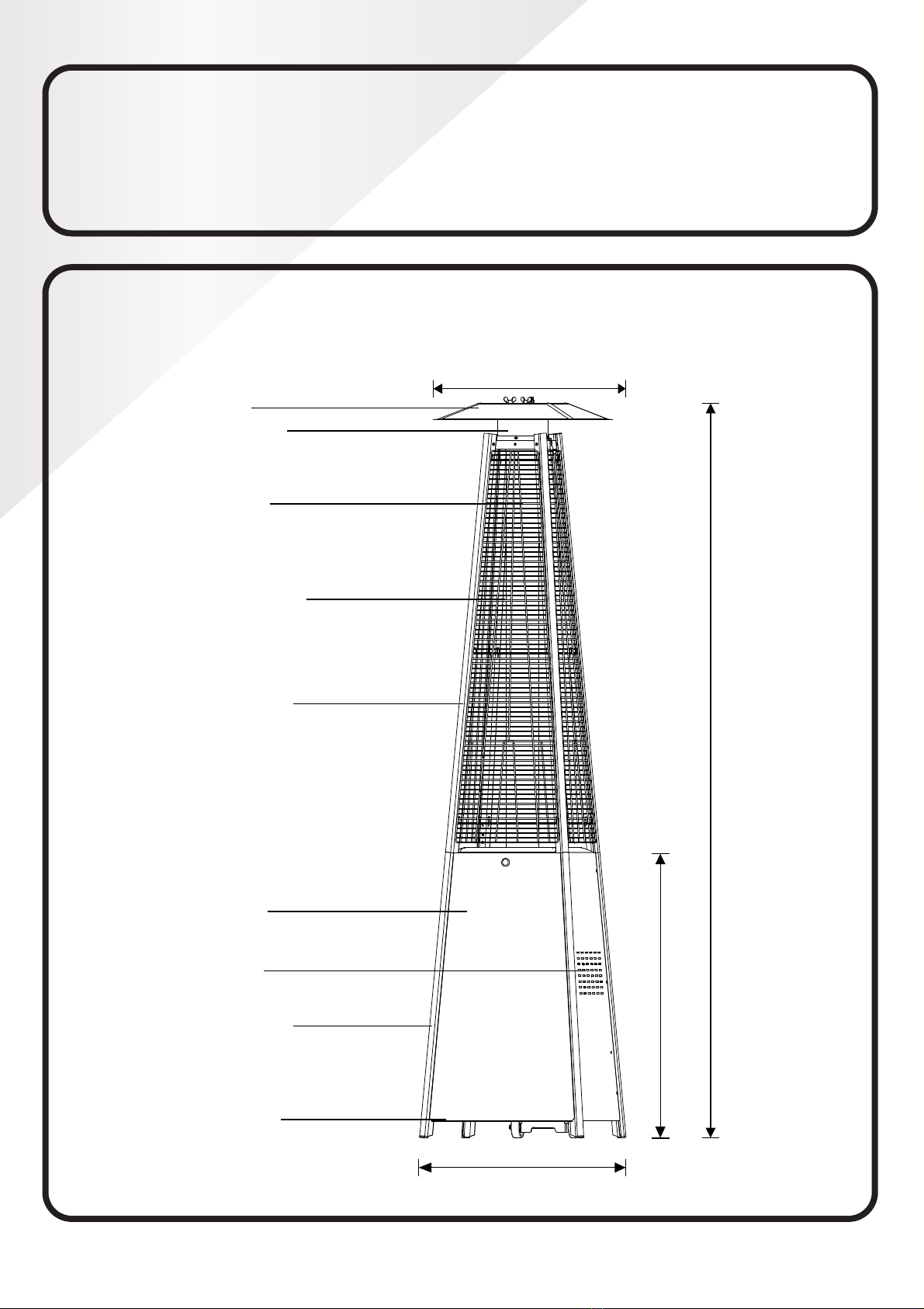
2270 mm
900 mm
650 mm
730 mm
Reflector
Glass Tube
Flame Screen
Protective Guard
Upper Support
Front Panel
Side Panel
Lower Support
Bottom plate
Front Panel
Side Panel
Lower Support
Bottom Plate
Upper Support
Protective Guard
Glass Tube
Flame Screen
Reector
730mm
900mm
2270mm
650mm
Pyramid Gas Patio Heater_IM_Wowcher_A4.indd 8Pyramid Gas Patio Heater_IM_Wowcher_A4.indd 8 12/05/2021 13:1512/05/2021 13:15

9
A. CONSTRUCTION AND CHARACTERISTICS
•
Transportable terrace/garden heater with gas cylinder housing.
• Casing in steel with powder-coating or in stainless steel.
• Gas hose connections with metal clamp (screw caps for Germany).
• Heatemissionfromreector.
B. SPECIFICATIONS
•
Use propane, butane or propane/butane mixture gas only.
• Max. wattage: 14kw
• Min. wattage: 6.8kw
• Consumption:
• Using the proper regulator according to outlet pressure of regulator as showed in the table above.
C. TABLE OF INJECTOR
•
The hose and regulator assembly must conform to local standard codes.
• Regulatoroutletpressureshouldmeetthecorrespondingappliancecategoryin‘B.Specications’table.
• The appliance requires approved hose in 0.6m length.
APPLIANCE CATEGORY: 3+(28-30/37) 3B/P(30) 3B/P(50)
TYPES OF GAS: Butane Propane Butane, propane
or their mixtures
Butane, propane
or their mixtures
GAS PRESSURE: 28-30 mbar 37 mbar 30 mbar 50 mbar
OUTLET PRESSURE
OF REGULATOR: 30 mbar 37 mbar 30 mbar 50 mbar
APPLIANCE CATEGORY: 3+(28-30/37) 3B/P(30) 3B/P(50)
TYPES OF GAS: Butane Propane Butane, propane
or their mixtures
Butane, propane
or their mixtures
GAS PRESSURE: 28-30 mbar 37 mbar 30 mbar 50 mbar
TOTAL HEAT
14kW (1019g/h)
INJECTOR SIZE: 1.89 mm for main burner
0.18 mm for pilot burner
1.55 mm for main burner
0.18 mm for pilot burner
The marking, for example, 1.89 on the injector indicates that the size of injector is 1.89mm
Pyramid Gas Patio Heater_IM_Wowcher_A4.indd 9Pyramid Gas Patio Heater_IM_Wowcher_A4.indd 9 12/05/2021 13:1512/05/2021 13:15
10
ASSEMBLY PARTS
Tools needed:
• Philips screwdriver w/ medium blade
• Spray bottle of soap solution for leakage test
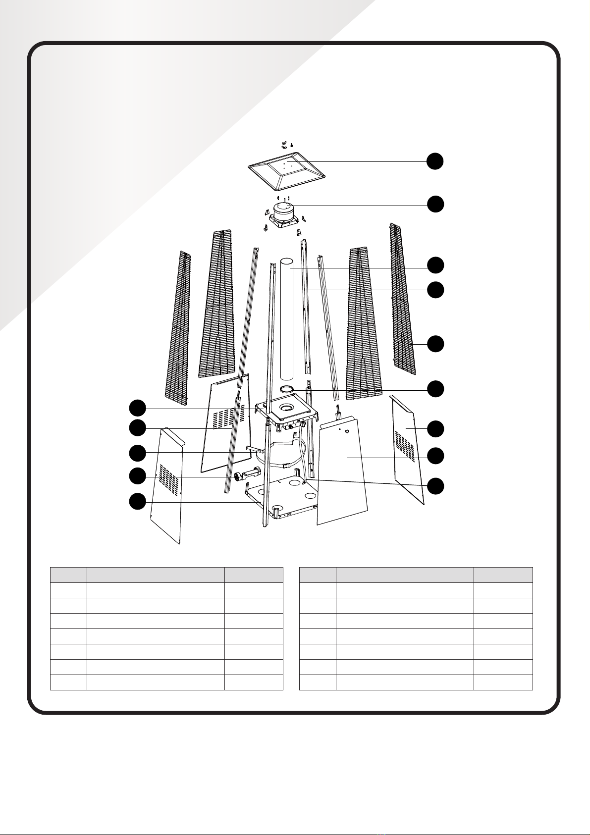
Parts List:
-6-
ASSEMBLY PARTS
Tools needed:
Philips screwdriver w/ medium blade
Spray bottle of soap solution for leakage test
Parts List:
NOITPIRCSEDTRAP QUANTITY
1
Flame Screen
1
L
M
N
Gas Hose
Control Box Assy
Lower Support
Block Belt
4
1
1
1
Wheel Assembly
Bottom Plate
NOITPIRCSEDTRAP QUANTITY
A
Reflector
1
B 1
C
Glass Tube
D
Upper Support
E
1
4
F
G
4
H
Black Silicone Ring
Protective Guard
I
Side Panel
J
Front Panel
K
1
3
1
Reflector
Flame Screen
Glass Tube
Protective Guard
A
B
C
Upper Support
Black Silicone Ring
D
E
Side Panel
F
G
Front Panel
H
Block Belt L
Lower Support K
Control Box Assy J
Gas Hose
I
Wheel Assembly M
Bottom Plate N
Control Box Assy
Lower Support
Block Belt
Wheel Assembly
Bottom Plate
Side Panel
Front Panel
Gas Hose
Black Silicone Ring
Protective Guard
Upper Support
Glass Tube
Flame Screen
Reector
PART DESCRIPTION
AReector 1
B Flame Screen 1
C Glass Tube 1
D Upper Support 4
E Protective Guard 4
F Black Silicone Ring 1
G Side Panel 3
PART DESCRIPTION
H Front Panel 1
I Gas Hose 1
J Control Box Assy 1
K Lower Support 4
L Block Belt 1
M Wheel Assembly 1
N Bottom Plate 1
Pyramid Gas Patio Heater_IM_Wowcher_A4.indd 10Pyramid Gas Patio Heater_IM_Wowcher_A4.indd 10 12/05/2021 13:1512/05/2021 13:15

11
ASSEMBLY PARTS
HARDWARE CONTENTS (shown actual size where applicable):
Wing nut
Qty. 3
Small at
washer Ф6
Qty. 6
Stud
Qty. 3
3/16” Screw
Qty. 42
Bolt M6 X 12
Qty. 4
M6 Flange
nut
Qty. 4
Screw
M5 x 12
Qty. 6 Fixing Bracket
Qty. 4
Wrench
Qty. 1
Philips
screwdriver
Qty. 1
Knob
Qty. 1
Screw
M4 X 6
Qty. 1
Chain
Qty. 1
Long Stem Lighter
Qty. 1
AA Battery (1.5 V)
Qty. 1
(NOT INCLUDED)
Pyramid Gas Patio Heater_IM_Wowcher_A4.indd 11Pyramid Gas Patio Heater_IM_Wowcher_A4.indd 11 12/05/2021 13:1512/05/2021 13:15
12
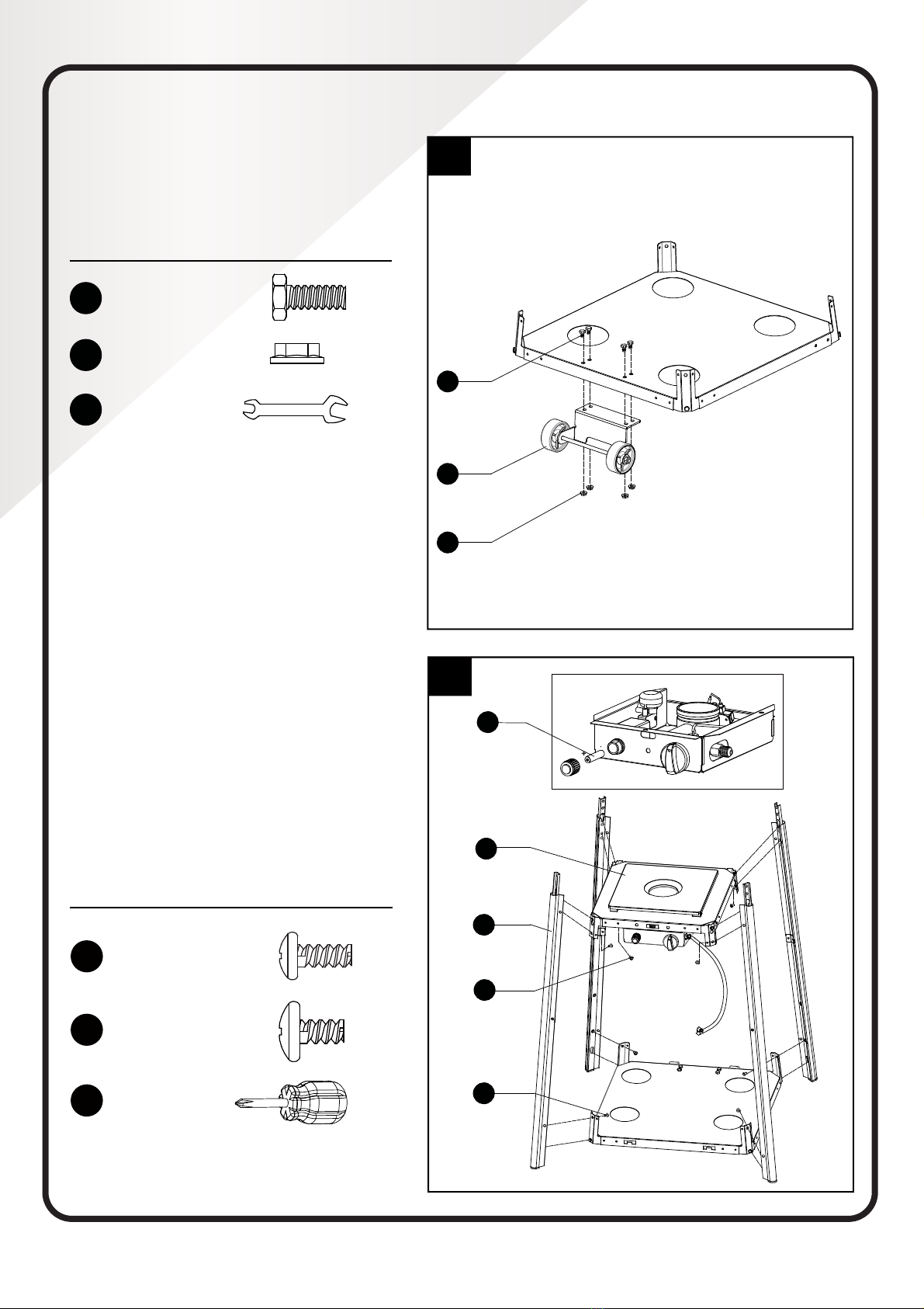
ASSEMBLY PROCEDURES
1. Assemble the wheel assembly to the bottom
plate. Fix the wheel assembly to the bottom
plateusing4pcsboltM6X12and4pcsange
nut M6.
-8-
ASSEMBLY PROCEDURES
Hardware Used
EE
FF
II
1
1. Assemble the wheel assembly to the
bottom plate. Fix the wheel assembly to the
bottom plate using 4pcs bolt M6X12 and 4pcs
flange nut M6.
x 4
x 4
Wrench x 1
M
J
K
DD
GG
OO
EE
FF
Bolt M6 X 12
M6 Flange nut
Hardware Used
2
2-1. Unscrew the switch button, load small
battery, tighten the switch button.
2-2. Insert the pins of the base to the holes of
lower support, press to secure the pins. Using
4pcs screw M5X12 to secure the lower support
and base.
Insert the pins of the control box assy to the
holes of upper support, press to secure the
pins. Using 4pcs screw 3/16” screw to secure
the upper support and control box assy.
GG
JJ
x 4
Philips
screwdriver x 1
Screw M5 X 12
DD x 4
3/16” Screw
AA Battery (1.5 V)
Hardware Used
Bolt M6 X 12 x 4
M6 Flange nut x 4
Wrench x 1
1
-8-
ASSEMBLY PROCEDURES
Hardware Used
EE
FF
II
1
1. Assemble the wheel assembly to the
bottom plate. Fix the wheel assembly to the
bottom plate using 4pcs bolt M6X12 and 4pcs
flange nut M6.
x 4
x 4
Wrench x 1
M
J
K
DD
GG
OO
EE
FF
Bolt M6 X 12
M6 Flange nut
Hardware Used
2
2-1. Unscrew the switch button, load small
battery, tighten the switch button.
2-2. Insert the pins of the base to the holes of
lower support, press to secure the pins. Using
4pcs screw M5X12 to secure the lower support
and base.
Insert the pins of the control box assy to the
holes of upper support, press to secure the
pins. Using 4pcs screw 3/16” screw to secure
the upper support and control box assy.
GG
JJ
x 4
Philips
screwdriver x 1
Screw M5 X 12
DD x 4
3/16” Screw
AA Battery (1.5 V)
2
AA Battery (1.5 V)
2.1 Unscrew the switch button, load the small
battery, tighten the switch button.
2.2 Insert the pins of the base to the holes of
lower support, press to secure the pins.
Using 4pcs screw M5X12 to secure the lower
support and base.
Insert the pins of the control box assy to the
holes of upper support, press to secure the
pins. Using 4pcs screw 3/16” screw to secure
the upper support and control box assy.
-8-
ASSEMBLY PROCEDURES
Hardware Used
EE
FF
II
1
1. Assemble the wheel assembly to the
bottom plate. Fix the wheel assembly to the
bottom plate using 4pcs bolt M6X12 and 4pcs
flange nut M6.
x 4
x 4
Wrench x 1
M
J
K
DD
GG
OO
EE
FF
Bolt M6 X 12
M6 Flange nut
Hardware Used
2
2-1. Unscrew the switch button, load small
battery, tighten the switch button.
2-2. Insert the pins of the base to the holes of
lower support, press to secure the pins. Using
4pcs screw M5X12 to secure the lower support
and base.
Insert the pins of the control box assy to the
holes of upper support, press to secure the
pins. Using 4pcs screw 3/16” screw to secure
the upper support and control box assy.
GG
JJ
x 4
Philips
screwdriver x 1
Screw M5 X 12
DD x 4
3/16” Screw
AA Battery (1.5 V)
Hardware Used
Screw M5 X 12 x 4
3/16” Screw x 4
Philips
screwdriver x 1
Pyramid Gas Patio Heater_IM_Wowcher_A4.indd 12Pyramid Gas Patio Heater_IM_Wowcher_A4.indd 12 12/05/2021 13:1512/05/2021 13:15
13
-9-
Hardware Used
JJ
Hardware Used
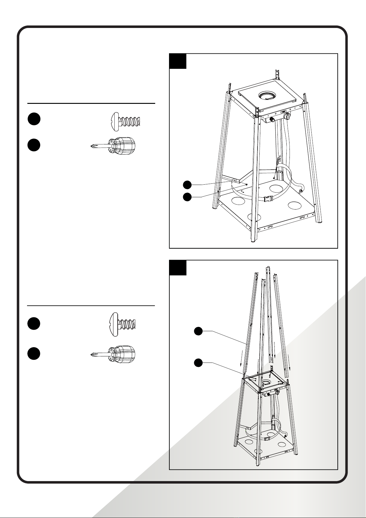
3. Assemble block belt.
Fix the block belt to the 2pcs of lower support
behind the front door, using 2pcs screw M5X12.
4.Assemble the middle support.
Insert the 4pcs upper support to the lower
support. Secure them with 8pcs screw 3/16”.
x 1
Philips
screwdriver
DD
JJ
x 8
x 1
Philips
screwdriver
3/16” Screw
GG x 2
Screw M5 X 12
3
4
L
GG
D
DD
ASSEMBLY PROCEDURES (cont’d)
3. Assemble block belt.
Fix the block belt to the 2pcs of lower support
behind the front door, using 2pcs screw
M5 X 12.
-9-
Hardware Used
JJ
Hardware Used
3. Assemble block belt.
Fix the block belt to the 2pcs of lower support
behind the front door, using 2pcs screw M5X12.
4.Assemble the middle support.
Insert the 4pcs upper support to the lower
support. Secure them with 8pcs screw 3/16”.
x 1
Philips
screwdriver
DD
JJ
x 8
x 1
Philips
screwdriver
3/16” Screw
GG x 2
Screw M5 X 12
3
4
L
GG
D
DD
Hardware Used
Screw M5 X 12 x 2
3
Philips
screwdriver x 1
-9-
Hardware Used
JJ
Hardware Used
3. Assemble block belt.
Fix the block belt to the 2pcs of lower support
behind the front door, using 2pcs screw M5X12.
4.Assemble the middle support.
Insert the 4pcs upper support to the lower
support. Secure them with 8pcs screw 3/16”.
x 1
Philips
screwdriver
DD
JJ
x 8
x 1
Philips
screwdriver
3/16” Screw
GG x 2
Screw M5 X 12
3
4
L
GG
D
DD
4
4. Assemble the middle support.
Insert the 4pcs upper support to the lower
support. Secure them with 8pcs screw 3/16”.
-9-
Hardware Used
JJ
Hardware Used
3. Assemble block belt.
Fix the block belt to the 2pcs of lower support
behind the front door, using 2pcs screw M5X12.
4.Assemble the middle support.
Insert the 4pcs upper support to the lower
support. Secure them with 8pcs screw 3/16”.
x 1
Philips
screwdriver
DD
JJ
x 8
x 1
Philips
screwdriver
3/16” Screw
GG x 2
Screw M5 X 12
3
4
L
GG
D
DD
Hardware Used
Philips
screwdriver x 1
3/16” Screw x 8
Pyramid Gas Patio Heater_IM_Wowcher_A4.indd 13Pyramid Gas Patio Heater_IM_Wowcher_A4.indd 13 12/05/2021 13:1512/05/2021 13:15

14
ASSEMBLY PROCEDURES (cont’d)
5.
support.
Securetheamescreentotheuppersupport
using 8pcs screw 3/16”.
- 10 -
Hardware Used
5
6
5. Assebmle the flame screen to the upper
support.
Secure the flame screen to the upper support
using 8pcs screw 3/16”.
6. Assemble the reflector onto the flame
screen.
Screw the 3pcs stud on the flame screen,
then put the reflector onto the stud, secure
nut.
AA
BB
CC
B
DD
x 3
x 3
x 6
Hardware Used
DD
JJ
x 8
Philips
screwdriver
3/16” Screw
x 1
AA
BB
Wing nut
CC Stud
Hardware Used
5
Philips
screwdriver x 1
5
- 10 -
Hardware Used
5
6
5. Assebmle the flame screen to the upper
support.
Secure the flame screen to the upper support
using 8pcs screw 3/16”.
6. Assemble the reflector onto the flame
screen.
Screw the 3pcs stud on the flame screen,
then put the reflector onto the stud, secure
nut.
AA
BB
CC
B
DD
x 3
x 3
x 6
Hardware Used
DD
JJ
x 8
Philips
screwdriver
3/16” Screw
x 1
AA
BB
Wing nut
CC Stud
3/16” Screw x 8
- 10 -
Hardware Used
5
6
5. Assebmle the flame screen to the upper
support.
Secure the flame screen to the upper support
using 8pcs screw 3/16”.
6. Assemble the reflector onto the flame
screen.
Screw the 3pcs stud on the flame screen,
then put the reflector onto the stud, secure
nut.
AA
BB
CC
B
DD
x 3
x 3
x 6
Hardware Used
DD
JJ
x 8
Philips
screwdriver
3/16” Screw
x 1
AA
BB
Wing nut
CC Stud
6
6.
screen.
Screwthe3pcsstudontheamescreen,put
3pcs washer Ф6 onto the top of stud, then
putthereectorontothestud,securethem
with 3pcs washer Ф6 and 3pcs wing nut.
- 10 -
Hardware Used
5
6
5. Assebmle the flame screen to the upper
support.
Secure the flame screen to the upper support
using 8pcs screw 3/16”.
6. Assemble the reflector onto the flame
screen.
Screw the 3pcs stud on the flame screen,
then put the reflector onto the stud, secure
nut.
AA
BB
CC
B
DD
x 3
x 3
x 6
Hardware Used
DD
JJ
x 8
Philips
screwdriver
3/16” Screw
x 1
AA
BB
Wing nut
CC Stud
Hardware Used
Wing nut x 3
Washer Ф6 x 6
Stud x 3
Pyramid Gas Patio Heater_IM_Wowcher_A4.indd 14Pyramid Gas Patio Heater_IM_Wowcher_A4.indd 14 12/05/2021 13:1512/05/2021 13:15

15
ASSEMBLY PROCEDURES (cont’d)
7. Carefully install the glass tube by lifting up
and inserting through the center hole in the
upper plate. Ensure the black silicone ring is
attached to the lower edge of the glass tube
as illustrated. Slide the glass tube through the
hole of the lower plate cover and onto the
middle plate. Check and ensure that the glass
tube is positioned properly and is completely
covering the center hole of the middle plate.
- 11 -
7
7. Carefully install the glass tube by lifting up
and inserting through the center hole in the
upper plate. Ensure the black silicone ring is
attached to the lower edge of the glass tube
as illustrated. Slide the glass tube through the
hole of the lower plate cover and onto the
middle plate. Check and ensure that the glass
tube is positioned properly and is completely
covering the center hole of the middle plate.
8. Assembly the protective guard.
Hang the hooks of the protective guard onto
the holes in supports.
Secure the protective guards with fixing
brackets with 4pcs 3/16" screws.
To aid in installation
place black silicone
ring on the middle
plate and then
install glass tube.
Ensure the rim of
the glass tube sits
firmly in the black
silicone ring.
WARNING! The black
silicone ring must be in place
prior to operating the heater.
BLACK SILICONE
RING
Hardware Used
DD
JJ
x 4
Philips
screwdriver
3/16” Screw
x 1
HH Fixing
Bracket x 4
8
E
DD
HH
7
5
To help with installation,
place the black silicone
ring on the middle plate
and then install the
glass tube. Ensure the
rim of the glass tube
sits rmly in the black
silicone ring.
Black Silicone
Ring
WARNING: The black
silicone ring must be in
place prior to operating
the heater.
- 11 -
7
7. Carefully install the glass tube by lifting up
and inserting through the center hole in the
upper plate. Ensure the black silicone ring is
attached to the lower edge of the glass tube
as illustrated. Slide the glass tube through the
hole of the lower plate cover and onto the
middle plate. Check and ensure that the glass
tube is positioned properly and is completely
covering the center hole of the middle plate.
8. Assembly the protective guard.
Hang the hooks of the protective guard onto
the holes in supports.
Secure the protective guards with fixing
brackets with 4pcs 3/16" screws.
To aid in installation
place black silicone
ring on the middle
plate and then
install glass tube.
Ensure the rim of
the glass tube sits
firmly in the black
silicone ring.
WARNING! The black
silicone ring must be in place
prior to operating the heater. BLACK SILICONE
RING
Hardware Used
DD
JJ
x 4
Philips
screwdriver
3/16” Screw
x 1
HH Fixing
Bracket x 4
8
E
DD
HH
8
- 11 -
7
7. Carefully install the glass tube by lifting up
and inserting through the center hole in the
upper plate. Ensure the black silicone ring is
attached to the lower edge of the glass tube
as illustrated. Slide the glass tube through the
hole of the lower plate cover and onto the
middle plate. Check and ensure that the glass
tube is positioned properly and is completely
covering the center hole of the middle plate.
8. Assembly the protective guard.
Hang the hooks of the protective guard onto
the holes in supports.
Secure the protective guards with fixing
brackets with 4pcs 3/16" screws.
To aid in installation
place black silicone
ring on the middle
plate and then
install glass tube.
Ensure the rim of
the glass tube sits
firmly in the black
silicone ring.
WARNING! The black
silicone ring must be in place
prior to operating the heater. BLACK SILICONE
RING
Hardware Used
DD
JJ
x 4
Philips
screwdriver
3/16” Screw
x 1
HH Fixing
Bracket x 4
8
E
DD
HH
Hardware Used
8. Assembly of the protective guard.
Hang the hooks of the protective guard onto
the holes in the supports.
Securetheprotectiveguardswithxing
brackets and with 4pcs 3/16” screws.
Philips
screwdriver x 1
3/16” Screw x 4
Fixing Bracket x 4
Pyramid Gas Patio Heater_IM_Wowcher_A4.indd 15Pyramid Gas Patio Heater_IM_Wowcher_A4.indd 15 12/05/2021 13:1512/05/2021 13:15
16
ASSEMBLY PROCEDURES (cont’d)
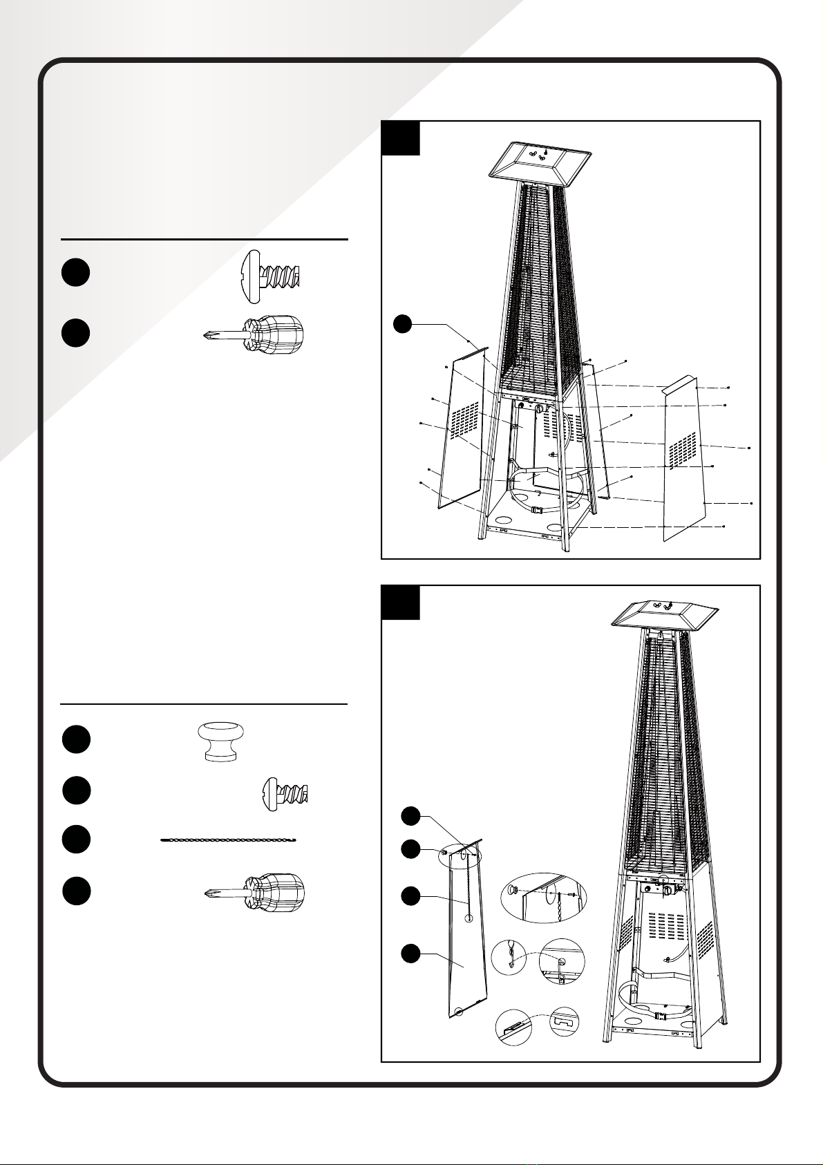
9. Attach the three side panels to the heater
using 18pcs screw 3/16”.
Note: Do not cover the front side where
the control knob is.
- 12 -
9
9. Attach the three side panels to the heater
using 18pcs screw 3/16”.
Note : Do not cover the front side where
the control knob is.
DD
Hardware Used
DD
JJ
x 18
Philips
screwdriver
3/16” Screw
x 1
10.Install the knob to M4X6 screw. Hang the
chain to the hole on the control box assy and
put the pothook of front panel to the holes of
bottom plate.
Hardware Used
x 1
KK
Knob
LL
JJ
x 1
x 1
Philips
screwdriver
Screw M4 X 6
x 1
MM
Chain
10
KK
LL
H
MM
9
5
- 12 -
9
9. Attach the three side panels to the heater
using 18pcs screw 3/16”.
Note : Do not cover the front side where
the control knob is.
DD
Hardware Used
DD
JJ
x 18
Philips
screwdriver
3/16” Screw
x 1
10.Install the knob to M4X6 screw. Hang the
chain to the hole on the control box assy and
put the pothook of front panel to the holes of
bottom plate.
Hardware Used
x 1
KK
Knob
LL
JJ
x 1
x 1
Philips
screwdriver
Screw M4 X 6
x 1
MM
Chain
10
KK
LL
H
MM
Hardware Used
Philips
screwdriver x 1
3/16” Screw x 18
- 12 -
9
9. Attach the three side panels to the heater
using 18pcs screw 3/16”.
Note : Do not cover the front side where
the control knob is.
DD
Hardware Used
DD
JJ
x 18
Philips
screwdriver
3/16” Screw
x 1
10.Install the knob to M4X6 screw. Hang the
chain to the hole on the control box assy and
put the pothook of front panel to the holes of
bottom plate.
Hardware Used
x 1
KK
Knob
LL
JJ
x 1
x 1
Philips
screwdriver
Screw M4 X 6
x 1
MM
Chain
10
KK
LL
H
MM
10
10. Install the knob to M4 X 6 screw. Hang the
chain to the hole on the control box assy
and put the pothook of the front panel to
the holes of the bottom plate.
Hardware Used
- 12 -
9
9. Attach the three side panels to the heater
using 18pcs screw 3/16”.
Note : Do not cover the front side where
the control knob is.
DD
Hardware Used
DD
JJ
x 18
Philips
screwdriver
3/16” Screw
x 1
10.Install the knob to M4X6 screw. Hang the
chain to the hole on the control box assy and
put the pothook of front panel to the holes of
bottom plate.
Hardware Used
x 1
KK
Knob
LL
JJ
x 1
x 1
Philips
screwdriver
Screw M4 X 6
x 1
MM
Chain
10
KK
LL
H
MM
Philips
screwdriver x 1
Knob x 1
Screw M4 x 6 x 1
Chain x 1
Pyramid Gas Patio Heater_IM_Wowcher_A4.indd 16Pyramid Gas Patio Heater_IM_Wowcher_A4.indd 16 12/05/2021 13:1512/05/2021 13:15

17
ASSEMBLY PROCEDURES (cont’d)
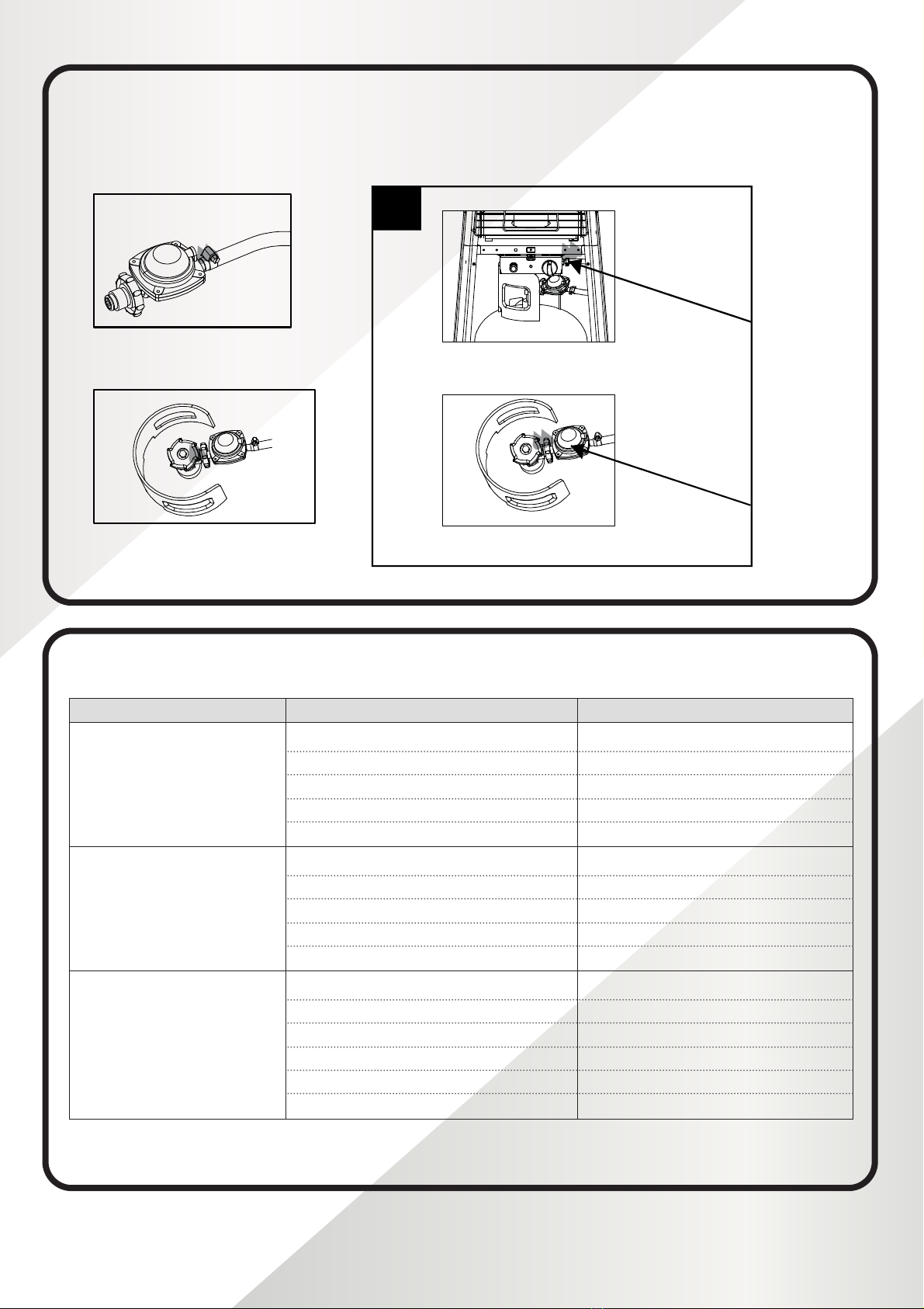
11. Connect the gas hose and regulator after that
connect the regulator to the gas cylinder.
- 13 -
11. Connect the gas hose and regulator after that
connect the regulator to the gas cylinder.
WARNING! Ensure the hose does not contact
any high temperature surfaces, or it may melt
and leak causing a fire.
After the cylinder is placed inside the heater, secure
the cylinder with block belt tightly.
12. Leak Check.
11
12
Regulator / Cylinder
Hose / Regulator
WARNING!
WARNING!
5
11
WARNING: Ensure the
hose does not get into
contact with any high
temperature surfaces as it
may melt and leak causing
After the cylinder is placed
inside the heater, tightly
secure the cylinder with the
block belt.
12. Leak Check.
WARNING: A leak test must be performed annually and each time a cylinder is hooked
up or if a part of the gas system is replaced.
WARNING:
LEAK TESTING: This must be done before initial use, annually, and whenever any
gas components are replaced or serviced. Do not smoke while performing this test, and
remove all sources of ignition. See Leak Testing Diagram on the next page for areas to
check. Turn all burner controls to the off position. Turn gas supply valve on.
of the regulator, hose, manifolds and valves.
with one recommended by the Customer Care department and have the patio heater
If the leak cannot be stopped, immediately shut off the gas supply, disconnect it, and have
until the leak has been corrected.
Pyramid Gas Patio Heater_IM_Wowcher_A4.indd 17Pyramid Gas Patio Heater_IM_Wowcher_A4.indd 17 12/05/2021 13:1512/05/2021 13:15
18
ASSEMBLY PROCEDURES (cont’d)
12. Leak Check.
Leak Testing Diagram for areas to check:
5
- 13 -
11. Connect the gas hose and regulator after that
connect the regulator to the gas cylinder.
WARNING! Ensure the hose does not contact
any high temperature surfaces, or it may melt
and leak causing a fire.
After the cylinder is placed inside the heater, secure
the cylinder with block belt tightly.
12. Leak Check.
11
12
Regulator / Cylinder
Hose / Regulator
WARNING!
WARNING!
12
Hose / Regulator
connection
Regulator / Cylinder
connection
5
In the event of any defaults or problems of assembly or use, please don’t try to modify it by yourself, contact
your supplier or distributor.
PROBLEMS CHECK LIST
PROBLEM PROBABLE CAUSE SOLUTION
Pilot will not light
Gas valve may be OFF
Tank fuel empty
Opening blocked
Air in supply system
Loose connections
Turn the gas valve ON
RellLPGtank
Clean or replace opening
Purge air from lines
Checkallttings
Pilot will not stay on
Debris around pilot
Loose connections
Thermocouple bad
Gas leak in line
Lack of fuel pressure
Clean dirty area
Tighten connections
Replace thermocouple
Check connections
Tanknearempty.RellLPGtank.
Burner will not light
Pressure is low
Opening blocked
Control not ON
Thermocouple bad
Pilot light assembly bent
Not in correct location
Tanknearempty.RellLPGtank.
Remove and clean
Turn valve to ON
Replace thermocouple
Place pilot properly
Position properly and retry
Pyramid Gas Patio Heater_IM_Wowcher_A4.indd 18Pyramid Gas Patio Heater_IM_Wowcher_A4.indd 18 12/05/2021 13:1512/05/2021 13:15
Table of contents
Popular Patio Heater manuals by other brands


Endless Summer
Endless Summer EWUR730SP owner's manual

dellonda
dellonda DG42 manual

Outback
Outback OUT370665/PH300 Assembly and operating instructions

Designers Edge
Designers Edge HEAT ZONE H-12000 manual

Blue Sky Outdoor Living
Blue Sky Outdoor Living WBFB33-T owner's manual

Blumfeldt
Blumfeldt Heat Guard manual


