Simpson SWT-525172 User manual
Part Number 7119888 / ENGLISH REV 1 - 12/2022
SAVE THIS MANUAL FOR FUTURE REFERENCE
USE AND CARE MANUAL
WATER TRAILER
READ THIS MANUAL CAREFULLY BEFORE OPERATION
Failure to follow the instructions and safety precautions in this manual can result
in property damage, serious injury and/or death.
NOTE: Photographs and line drawings used in this manual are for reference only and may not
represent your specic model.
If your unit is not working or if there are parts missing or broken, please DO NOT RETURN IT TO THE
PLACE OF PURCHASE. Contact our Customer Service Department by calling 1-877-362-4271 or
emailing [email protected]
LOOK BEFORE YOU PUMP!

Page II
NOTES
THIS PAGE WAS INTENTIONALLY LEFT BLANK

Page 1
SAVE THIS MANUAL FOR FUTURE USE
Write down the model number, serial number, and purchase date of this product in the spaces
provided below then keep this manual with the purchase receipt(s) for future reference.
Keep this manual for future reference. This manual should be considered a permanent part
of the product and stay with it. This manual should be available to anyone operating the
product(s) it covers. This manual should remain with the product(s) it covers if sold to a new
owner. If the manual becomes damaged, lost, or otherwise unusable, you may download
a new copy from the product pages at www.simpsoncleaning.com or contact customer
support by calling 1-877-362-4271.
Model Number:
Serial Number:
Purchase Date:

Page 2
TABLE OF CONTENTS
DISCLAIMERS 5
Hazard Alert Symbols 4
Additional Instructions 4
Read this Manual Before Operating 4
4SAFETY INSTRUCTIONS
COMPONENT LOCATION 6
PRESSURE FILLING THE TANK 9
SETTING THE FLOW VALVES 10
SETTING THE MANIFOLD VALVES 11
SIDE PORT (DISCHARGE OR SUCTION)
12
FILLING THE TANK FROM A
STANDING WATER SOURCE
13
USING THE SIDE PORT OUTPUT 15
USING THE SPRAY BAR 16
DRAINING THE SYSTEM FOR
STORAGE (WINTERIZE)
17
Draining the System 17
TRAILERING SYSTEM 18
Trailer Coupler 18
OPERATING CHECKLIST 22
Location 22
High Altitude Operation 22
Operating Conditions 22
Checking the Engine Oil 24
Checking Fuel 25
Adjusting the Trailer Coupler Height 19
Trailer Electrical System 20
PRESSURE FILL PIPE INSTALLATION 8

Page 3
27STARTING THE ENGINE
29
TURNING THE ENGINE OFF
29
TROUBLESHOOTING
MAINTENANCE 30
Pump Maintenance 30
Exterior Pump Cleaning 30
Interior Pump Cleaning 31
Engine Maintenance 33
Plumbing Maintenance 33
Trailer Maintenance 33
ENGINE LONGTERM STORAGE 34
Storing for Two Months or Less 34
Storing for More Than Two Months 34
WARRANTY 35

CAUTION:CAUTION:
NOTICE
Page 4
This manual contains important safety information and instructions. Do not operate
this product until you have read, and completely understand all safety, operation, and
maintenance instructions listed in this manual. Failure to follow the information contained
in this manual will result in property damage, injury, and/or death.
NOTE: The warnings and precautions discussed in this manual cannot cover all conditions
and situations that may occur. The operator must understand awareness and caution are
factors which cannot be built into this product and so must be exercised by the operator.
READ THIS MANUAL BEFORE OPERATING
ADDITIONAL INSTRUCTIONS
Be sure to understand the safety symbols and denitions listed below. Each symbol
contains one of four words: DANGER, WARNING, CAUTION, NOTICE, indicating
dierent levels of hazard severity. These symbols are used throughout this manual and
are followed information about a specic hazard, the consequences of the hazard, and
instructions on how to avoid the hazard. Failure to heed these symbols and follow the
instructions provided with them will result in property damage, injury, and/or death.
HAZARD ALERT SYMBOLS
Indicates an imminently dangerous situation, which if not
avoided, will result in property damage, serious injury, and/
or death.
Indicates a potentially hazardous situation, which if not
avoided, could result in property damage, serious injury, and/
or death.
Indicates a hazardous situation, which if not avoided, could
result in property damage and/or minor to moderate injury.
Indicates information considered important, but not directly
hazard related.
SAFETY INSTRUCTIONS
Along with this manual, be sure to read any additional instructions provided both on and
with the product, attached equipment, accessories, and the engine powering the product.
Pay careful attention to all additional safety rules and instructions on proper startup,
operation, and shutdown procedures. Always use any recommended protective apparel
that may be needed to operate the equipment safely.
DANGER:DANGER:
WARNING:WARNING:

Attempting to start the engine incorrectly or using the unit incorrectly can result in engine
and/or pump failure and may cause serious injury or death. To avoid these hazards, be
sure to read, understand, and follow the steps outlined in the OPERATING CHECKLIST
section of the owner’s manual before starting the engine and follow all the guidelines for
proper use of the unit.
OPERATING CHECKLIST
WARNING:WARNING:
The SIMPSON Water Trailer is designed to be used only with fresh or gray water. Do not
pump or transport euent, black (sewage) water or any types of chemicals. Do not pump
or transport any uid that is intended for human consumption.
FLUID USAGE
WARNING:WARNING:
Page 5
This product and the engine exhaust can expose you to chemicals which are known to
the state of California to cause cancer, birth defects, or other reproductive harm. For
more information on California Proposition 65, go to www.P65Warnings.ca.gov.
CALIFORNIA PROPOSITION 65 WARNING
POLYCYCLIC AROMATIC HYDROCARBON WARNING
The air lter element and air box assembly may contain polycyclic aromatic hydrocarbons
(PAHs). Some PAHs may cause cancer. To avoid exposure to PAHs, wear gloves when
performing air lter maintenance.
DISCLAIMERS
SAVE THIS MANUAL FOR FUTURE USE.
All information in this publication was based on the latest product information
available at the time of printing. The FNA Group reserves the right to update,
change, and/or improve the product and this document at any time, without
notice and without incurring any obligation.
This manual may cover more than one machine. The pictures and gures
in the manual should be used for reference only. There may be dierences
between your product and the pictures, drawings and diagrams in this manual.
If you loan, rent or sell this machine, be sure to include all instructional materials
with the unit!
Page 6
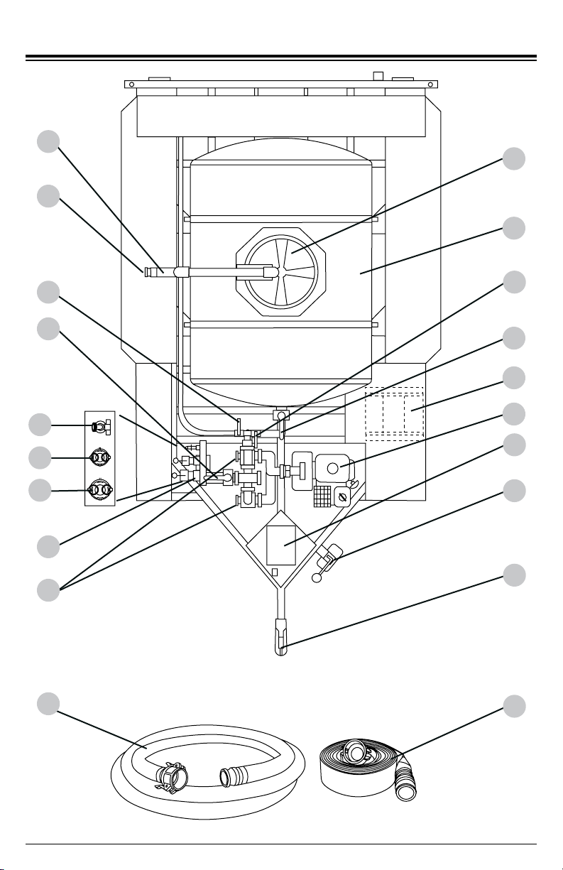
COMPONENT LOCATION
1
2
4
6
8
9
13
11
7
15
5
25
26
27
310
12
14
16
17

Page 7
18 19 20 21 22 23
3. Spray bar control valve, see page 11.
4. Side port control valve, see page 11.
5. Side port, see page 12.
6. Flow control valves, see page 10.
8. Vented tank cover.
9. Tank.
10.
Hose reel (optional) valve, see page 11.
11.
Tank valve, see page 11.
15. Trailer jack.
16. Trailer coupler, see page 18.
18. Red turn/brake light.
19. License plate holder.
20. License plate light.
21. Hose storage bin.
22. Spray bar assembly, see page 16.
23. Spray nozzle (one of two).
24. Amber marker light.
25. Side port garden hose bibb.
1. Pressure ll pipe, see pages 8 & 9.
2. Pressure ll pipe 2” hose connector.
7. 20ft (6.1M) Suction rated hose.
17. 50ft (15.2M) lay at discharge hose.
26. Side port 1.5” connector.
27. Side port 2” connector.
12. Hose reel (optional).
24
14. Protective cover for electrical
components including the break-
away system control, see page 21.
13.
Gasoline powered pump, see page 27
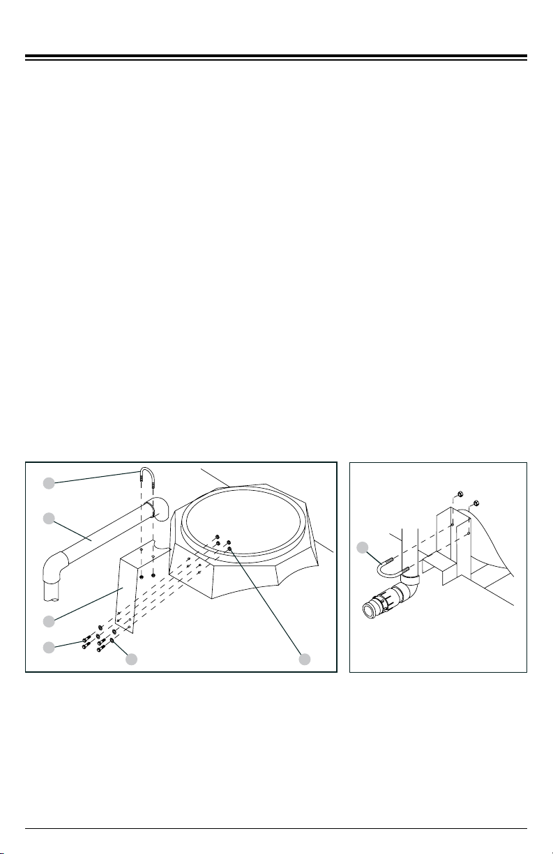
PRESSURE FILL PIPE INSTALLATION
The following tools are required:
(2) 1/2” open end wrenches
(1) 9/16” open end wrench
Please locate the pressure ll pipe in the hose storage bin at the rear of the trailer. Along
with it will be a bag containing the required hardware and U-bolts. Unwrap the protective
plastic from the pipe.
Step 1: Remove the cover from the top of the tank.
Step 2: Using the 5/16” hex bolts (2), 5/16” at washers (3) and 5/16” nylon insert lock
nuts (4), attach the ll pipe bracket (1) to the tank using 1/2” open end wrenches
(Fig. A).
Step 3: Place the pressure ll pipe (5) allowing the elbow to t into the circular relief of
the bracket (Fig. A). Attach using one of the included U-bolts (6). At this time,
only hand thread the nuts, do not tighten.
1
2
3 4
6
5
Fig. A
Step 4: Using the remaining U-bolt (6), attach the pressure ll pipe to the lower bracket
(Fig. B). Tighten both U-bolts using a 9/16” open end wrench.
Step 5: Place the cover back onto the tank.
Fig. B
6
Page 8
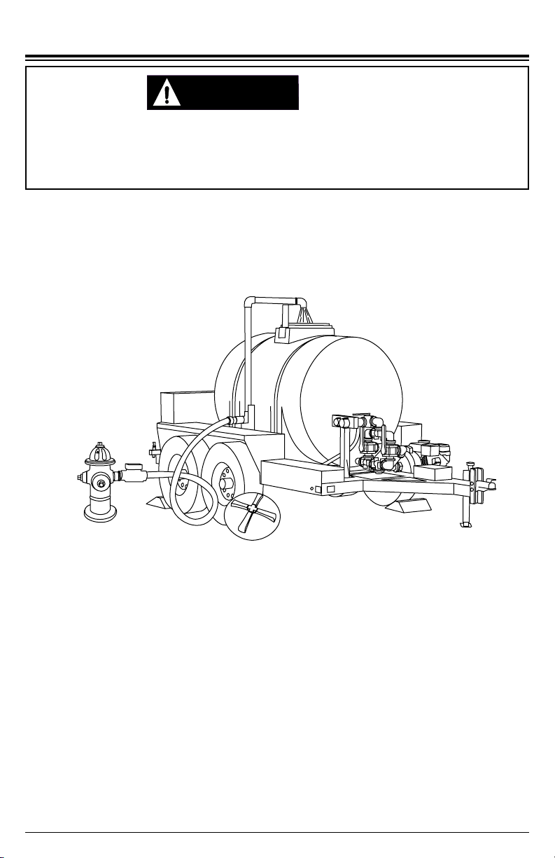
PRESSURE FILLING THE TANK
CAUTION:CAUTION:
Page 9
The tank can be lled from a pressurized water source by using the 2” tank ll on
the passenger’s side of the trailer. NOTE: Do not use a re hydrant unless you have
contacted your local municipality. Typically the water will need to be metered and a
back ow preventer may need to be placed with the meter by the municipal water
department.
1. Remove the cover of the tank.
2. Connect a 2” hose from the pressurized water source to the ll connector.
3. Turn on the water source allowing the tank to ll to the required level.
4. Turn o the water source then disconnect the hose from the ll pipe.
5. Place the cover back onto the tank, secure.
Whenever the trailer is disconnected from the tow vehicle, the trailer should be parked
on a level surface and with the wheels chocked (not included). Trailers with non-chocked
wheels can roll when parked on non-level pavement or when accidentally bumped from
another vehicle leading to injury/death and property damage.
TRAILER MOVEMENT

SETTING THE FLOW VALVES
Page 10
Along with the ability to pump water out (to the spray bar, for example), the SIMPSON
Water Trailer also has the capability to ll its tank from a standing water source such
as a lake, stream or pond.
To pump water from the tank (pump position) the valve handles must be set in the
upward position, (Fig. 1).
The ow valves are what routes the water through the pump. The valves must be set
so the water can either be sent to, or taken from, the tank.
In order to ll the tank (draw position) the valve handles must be set in the downward
position, (Fig. 2).
Fig. 1 (Pump Position) Fig. 2 (Draw Position)
Input
Output
CAUTION:CAUTION:
Failure to properly set the valves can cause damage to the pump and the piping. Always
set the valves and verify the pump is properly primed before starting the engine.
PUMP DAMAGE
Input
Output
NOTICE
This pump will not prime when dry. Running the pump dry without priming can damage the
pump assembly and seals. Damage caused by running dry is not covered by warranty.
To avoid damaging the seals and pump assembly, do not run the pump when it is dry
without priming.
PUMP PRIMING

SETTING THE MANIFOLD VALVES
Page 11
Above the pump is a horizontal manifold (Fig. 3) that contains two valves (spray bar
valve and the passenger’s port side valve). See USING THE SPRAY BAR or USING
THE SIDE PORT, to determine which valve to use. Below the horizontal manifold is
the tank valve.
Spray bar
valve
Passenger’s
side port
Driver’s
side port
(optional)
The valve is open (water ows through) when the handle is in-line with the valve body.
The valve is closed (water cannot ow) when the handle is perpendicular to the valve
body. (See Fig. 4)
Passenger’s side port valve Driver’s side port valve (optional)
Fig. 3
Fig. 4
Valve closed Valve open
Tank valve
Hose reel
(optional)
valve

SIDE PORT (DISCHARGE or SUCTION)
Always have the dust covers in place and locked before moving the trailer. Loose covers
may come free at highway speeds leading to injury. Make it a point each time you will be
moving the trailer to inspect the dust covers and verify they are properly locked.
DUST COVERS
WARNING:WARNING:
Page 12
The side ports allows you to send water out to a hose (for example, irrigation) or using
a hose to draw water into the tank (1.5 or 2” only).
The port assembly contains a 1.5” hose connector, a 2” hose connector and a standard
3/4” garden hose bibb. (See Fig. 5)
1.5” Hose 2” Hose
3/4” Hose bibb
Fig. 5
The 1.5” and 2” hose connectors have cam lever dust covers (Fig. 6) that are chained
to the side port for retention. Always have the covers in place and locked before
moving the trailer. Loose covers may come free at highway speeds leading to injury.
CAUTION:CAUTION:
When pumping from a standing source using the side port, only use the 1.5” or 2” hose
connectors. The 3/4” hose bibb is too restrictive and could damage the pump due to
insucient water ow.
PUMP DAMAGE
Fig. 6
Place the cover on the hose
connector then rotate the
cams to lock the cover onto
the connector.
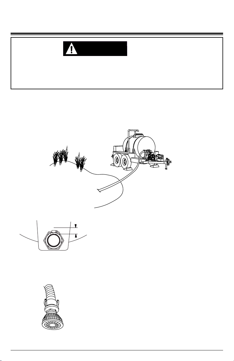
FILLING THE TANK FROM A STANDING
WATER SOURCE
Page 13
Besides lling the tank from a pressurized sources of water, you also have the ability
to ll the tank from a standing source of water (Fig. 7) such as a lake, stream or pond.
In order to do this, you will need to use the 2” rigid suction hose and the on-board
pump. We recommend using a strainer / lter (not included) on the suction hose.
Fig. 7
2. Place a lter / strainer (not included) onto the end
of the rigid suction hose (Fig. 9), before placing the
hose into the water. NOTE: The total lift from the
lter / strainer to the level of the side port must not
exceed 25 feet (7.6 meters).
1. In order to ll the tank from a standing source,
you must have water in the tank at a minimum of
1” above the outlet pipe (Fig. 8). If you do not have
a sucient amount of water in the tank, you will
need to ll the tank from a pressurized source; see
PRESSURE FILLING THE TANK.
Fig. 9
Fig. 8
1” min.
Whenever the trailer is disconnected from the tow vehicle, the trailer should be parked
on a level surface and with the wheels chocked (not included). Trailers with non-chocked
wheels can roll when parked on non-level pavement or when accidentally bumped from
another vehicle leading to injury/death and property damage.
TRAILER MOVEMENT
CAUTION:CAUTION:

NOTICE
Page 14
3. Connect the other end of the hose to the side port (Fig. 5).
4. Remove the primer cover on the pump (Fig. 10) then ll the pump with water. Place
the cover back onto the funnel, tighten.
6. Move the ow valves to the DRAW position (Fig. 2).
7. Make sure the spray bar and side port valves are CLOSED (Figs. 3 & 4).
CAUTION:CAUTION:
In order to ll the tank with the DRAW function, you must have at least one inch of water
above the outlet pipe of the tank. Water below this level may not be sucient to prime
the suction hose.
PUMP DAMAGE
8. Using the STARTING THE ENGINE instructions, start the engine of the pump.
9. Move the side port valve to OPEN (Fig. 4). You may notice air bubbles in the tank as
the water starts to ow. If the pump fails to prime, stop the engine and repeat step 4.
10. Wait until the tank is lled to the required level.
11. Once the tank is lled, move the side port valve to CLOSED.
12. Shut o the engine by using the SHUTDOWN instructions.
13. Move the tank valve to the CLOSED position
.
Fig. 10
We recommended having a lter (not included) on the end of the suction hose. Not using
a lter can introduce debris into the pump and the tank that may cause damage. Always
place the lter at a depth where air cannot be introduced into the system, but do not allow
it to sit on the muddy bottom of the source.
5. Move the tank valve to OPEN (Fig. 3).
14. Disconnect the hose then place the cover on the hose bard; lock into place (Fi
g. 6).
PUMP DAMAGE

USING THE SIDE PORT OUTPUT
Page 15
The side port outputs can be used for a variety watering uses. As talked about in
SIDE PORT (DISCHARGE or SUCTION), you have the ability to use a standard 3/4”
garden hose, a 1.5” or a 2” hose as the output. In order to use these outputs, make
sure the tank is fully lled or has enough water for your application. Do not allow the
pump to go dry as damage may occur.
2. Ensure the pump is primed. If you start to remove the primer cover and water
begins to ow out, it is primed. If not, remove the cover and ll the pump with water
(Fig. 10). Thread the cover back onto the funnel, tighten.
3. Move the ow valves to the PUMP position (Fig. 1).
4. Make sure the spray bar and side port valves are closed (Figs. 3 & 4).
5. Connect the hose to the appropriate side port connection (1.5”, 2” or 3/4” garden
hose).(Fig. 5).
6. If using a 3/4” garden hose, rotate the hose bibb handle to ON (Fig. 11).
7. Using the STARTING THE ENGINE instructions, start the engine of the pump.
8. Move the side port valve to OPEN (Fig. 4).
9. Use the output until your application is completed or you have met the minimum
allowed amount of water in the tank. DO NOT allow the tank to pump dry.
10. Move the side port valve to CLOSED.
11. Shut o the engine by using the SHUTDOWN instructions.
13. Disconnect the hose then place the cover on the hose bard, lock into place (Fi
g. 6)
-or- rotate the hose bibb handle to CLOSED.
Fig. 11
OFF ON
CAUTION:CAUTION:
Never allow the tank water level to fall below a level of one inch above the outlet pipe of
the tank. If the tank fully drains, pump damage may occur from lack of water and you will
only be able to rell the tank from a pressurized water source.
PUMP DAMAGE
1. Move the tank valve to OPEN (Fig. 3).
12. Move the tank valve to CLOSED.

USING THE SPRAY BAR
Page 16
The spray bar allows you to water down areas for dust reduction as well as washing
the pavement of loose dirt and debris. In order to use the spray bar, make sure the
tank is fully lled or has enough water for your application. Do not allow the pump to
go dry as damage may occur.
CAUTION:CAUTION:
Never allow the tank water level to fall below a level of one inch above the outlet pipe of
the tank. If the tank fully drains, pump damage may occur from lack of water and you will
only be able to rell the tank from a pressurized water source.
PUMP DAMAGE
2. Ensure the pump is primed. If you start to remove the primer cover and water
begins to ow out, it is primed. If not, remove the cover and ll the pump with water
(Fig. 10). Place the cover back onto the funnel, tighten.
3. Move the ow valves to the PUMP position (Fig. 1).
4. Make sure the spray bar and side port valves are closed (Figs. 3 & 4).
5. Using the STARTING THE ENGINE instructions, start the engine of the pump.
6. Move the spray bar valve to OPEN (Fig. 4).
7. Use the spray bar until your application is completed or you have met the minimum
allowed amount of water in the tank. DO NOT allow the tank to pump dry.
8. Move the spray bar valve to CLOSED.
9. Shut o the engine by using the SHUTDOWN instructions.
1. Move the tank valve to OPEN (Fig. 3).
10. Move the tank valve to CLOSED.
Page 17
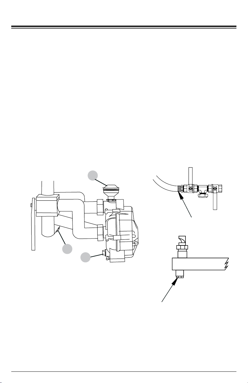
DRAINING THE SYSTEM FOR STORAGE (WINTERIZE)
When you will not be using the trailer for an extended period of time or there is a
chance of freezing weather, you should drain the system.
2.
Using a screw or nut driver, loosen the worm screw clamp (Fig. 12-A). Carefully
remove it and the manifold plug from the tee ange.
3. Remove the drain plug on the bottom of the pump (Fig. 12 - B).
1. Ensure the trailer is as level as possible.
4. Remove the primer cover from the pump allowing air into the pump (Fig. 12 - C).
5. As the system drains, operate the ow valves (Figs. 1 & 2) to allow any trapped
water to drain.
6. Once the water has stopped owing, replace the caps and manifold plug; tighten.
C
Fig. 12
7. Move the tank valve to the CLOSED position.
DRAINING THE SYSTEM
A
4. Open the tank valve to allow the tank to empty
8. Using a screw or nut driver, loosen the hose clamp (Fig. 13). Carefully remove the
hose and lower it allowing residual water to drain.
9. Remove the drain plugs from the bottom of the spray bar near each nozzle (Fig. 14).
10. Allow any trapped water to drain from the hose and the spray bar.
Fig. 13
Fig. 14
11. Thread in the drain plugs; tighten.
12. Align the hose assembly back with the manifold, position the clamp and tighten.
B

NOTICE
Page 18
TRAILERING SYSTEM
The trailer coupler of the SIMPSON Water Trailer is adjustable in height. It is important
to keep the trailer as level as possible with the tow vehicle. This is accomplished by
raising or lowering the coupler within the channel.
1
2
3
4
5
6
7
8
1. Coupler retaining bolt and nylon-insert locknut
2. Safety cable retaining hair pin -or- cotter pin
Safety cable assembly
4. Safety pin and lanyard
5. Latch
6. Coupler
7. Coupler channel
8. Snap hook
3.
Whenever the trailer is disconnected from the tow vehicle, the trailer should be parked
on a level surface and with the wheels chocked (not included). Trailers with non-chocked
wheels can roll when parked on non-level pavement or when accidentally bumped from
another vehicle leading to injury/death and property damage.
TRAILER MOVEMENT
CAUTION:CAUTION:
TRAILER COUPLER
When the trailer was ordered, you
should have picked the coupler
that matched your hitch. If you did
not specify a coupler or did not
receive one, please contact our
Customer Service Department by
calling 1-877-362-4271 or emailing
Table of contents


