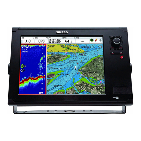
Simrad ce32 mkii User manual

.OTE Insert or remove C-MAP cartridges ONLY thru CHART
menu or when unit is off.
All electronic navigation equipment is subject to external factors
beyond the control of the manufacturer. Therefore such equipment
must be regarded as an aid to navigation. The prudent navigator
will, for that reason, never rely on a single source for position
fixing and navigation.
3)-2!$#%-+))
$'03#HART3OUNDER
%NGLISH

In case someone falls overboard, press the [MOB] key
and hold for two seconds (or activate an external MOB
switch), and the system will provide you with all rele-
vant data for an efficient rescue operation.
An alarm will sound if the
function is activated from
an external MOB switch.
Press [CLR] to confirm
and reset the alarm.
The -/"display will
provide present course,
bearing and distance to
the MOB position.
Elapsed time - first in sec-
onds and then in minutes
(*=over 9999 minutes).
'OTOGRAPHICAL-/"DISPLAY
The # !24display will provide a graphical impres-
sion of the MOB position - a man waving his arms in
relation to the ship.
0RESS[WIN] REPEATEDLYTORETURNTOTHE-/"DISPLAY
0RESS[MENU], [4],AND[3]TOTURNTHE-/"FUNCTIONOFF
0RESS[MENU], [2],AND[6]TORECALLTHELAST-/"POSI
TIONPLUSTHEEXACTTIMEANDDATEOFTHEINCIDENT
-/" -!./6%2"/!2$ FUNCTION
KEYSTOPRESS
MOB
SEC S
MAN OVERBOARD
C241° B113°
DIST 1.89nm
TIME 8min
MOB 56°52.743N
POS 9°46.572E
Stop MOB: MENU 4+3
WIN
2,6MENU
4,3MENU
GOTO

)NTRODUCTION 5
&UNDAMENTALSANDINITIAL
STARTUP
2.1 Keypad ....................................... 7
2.2 Getting started............................ 9
2.3 Menu bar .................................. 11
2.4 Menu layout ............................. 12
#HARTANDPOSITIONMENUS
3.1 Chart menu............................... 13
3.1.1 Chart...................................... 13
3.1.2 C-MAP cartridges................. 17
3.1.3 Chart setup 1 ......................... 19
3.1.4 Chart setup 2 ......................... 20
3.2 Position menu .......................... 21
3.2.1 Position display..................... 22
3.2.2 Course and speed .................. 24
3.2.3 Dual speed/position disp....... 24
3.2.4 Decca lanes ........................... 26
3.2.5 Loran C ................................ 27
3.2.6 Position setup........................ 28
3.3 Speed diagram.......................... 31
3.4 DGPS information ................... 32
7AYPOINTSNAVIGATION
4.1 Navigation menu...................... 33
4.1.1 Chart/cursor navigation ........ 33
4.1.2 Navigation display................ 34
4.1.3 Estimated time of arrival ...... 35
4.1.4 Create route by cursor........... 36
4.1.5 Waypoint navigation............. 37
4.1.6 Make a route by using
the waypoint list ................... 37
4.1.7 Route navigation................... 40
4.1.8 Route calculation .................. 41
4.1.9 Editing of route ..................... 42
4.1.10 Track navigation ................. 47
4.2 WP/Route menu ....................... 48
4.2.1 Marks and waypoints ............48
4.2.2 Plot cursor position on chart . 49
4.2.3 Plot mark or waypoint as
ship’s position ....................... 52
4.2.4 Plot mark/waypoint
via WPlist.............................. 53
4.2.5 Edit mark/waypoint............... 54
4.2.6 Delete mark/waypoint........... 56
4.2.7 Trackplotting......................... 57
4.2.8 Lines (drawing)..................... 59
4.2.9 Targets................................... 61
4.2.10 Data transfer........................ 63
CHOSOUNDEROPERATION
5.1 Echo sounder operation ........... 67
5.2 Echo sounder menu.................. 68
5.2.1 Echo display.......................... 68
5.2.2 Bottom expansion ................. 70
5.2.3 VRM expansion .................... 70
5.2.4 A-scope ................................. 71
5.2.5 Variable Range Marker.......... 71
5.2.6 Presentation setup ................. 72
5.2.7 Echo sounder setup ............... 73
5.3 How the echo sounder
works........................................ 74
5.3.1 Transducer beamwidth.......... 75
5.3.2 Effects of vessel’s speed ....... 76
3ETUP
6.1 Setup menu............................... 77
6.1.1 Navigation setup ................... 77
6.1.2 Setup for display colors ........ 80
6.1.3 Setup for speed alarm,
units & language .................. 81
6.1.4 Set & drift display................. 83
4ABLEOFCONTENTS
)NTERFACINGANDMASTERRESET
7.1 Interface settings ...................... 85
7.1.1 Interface setup....................... 85
7.2 Wind instrument display.......... 88
7.3 Master reset.............................. 90
)NSTALLATIONANDSERVICE
8.1 Installation of CE32 MKII ...... 91
8.2 Installation of DC30 ................ 92
8.2.1 Operation of DC30 ............... 92
8.3 Installation of antenna.............. 93
8.4 Electrical connections.............. 95
8.4.1 Power supply connect. .......... 96
8.4.2 Transducer connections ........ 96
8.4.3 Fuse ....................................... 96
8.4.4 NMEA 0183 interface
connections .......................... 96
8.5 Transducer connections ........... 97
8.5.1 Position for transducer.......... 99
8.6 Optional connections ............. 100
8.7 Maintenance........................... 101
8.8 Troubleshooting procedure.... 102
8.9 Specifications......................... 103
!PPENDIX!
Glossary of terms ........................... 104
!PPENDIX"
List of datums ................................ 111
!PPENDIX#
TideTracker feature (only
available in US version)................. 113
!PPENDIX$
C-MAP Port & Tide information .. 119
Index...............................................122
CE Declaration of Conformity.......126
Terms of warranty.......................... 127
List of Simrad Distributors
4ABLEOFCONTENTS
Congratulations on your purchase of 3)-2!$$'03#HART3OUNDER
#%-+)) Great care has been taken to create the ultimate naviga-
tion aid .... both in design and performance. The CE32 MKII is a
unique combination of the latest GPS receiver technology and built-in
differential* receiver for accurate positioning, detailed cartography
and high performance echosounder in a compact design with a 6"
large LCD display in TFT color or monochrome.
3IMRAD# -+))ISAVAILABLEWITHORWITHOUTDIFFERENTIAL'03
4HE#%-+))CHARTSYSTEM includes a built-in world chart for
rough planning and overview. The choice of chart system best suitable
for the SIMRAD CE32 MKII was carefully singled out to be the
#-!0MINICARDS#&. The optional C-MAP charts are available
world-wide at your local Simrad dealer.
4HEECHOSOUNDERSYSTEM with selectable frequencies will provide an
impression of Bottom expansion, VRM expansion, A-scope and white
line.
4HE'LOBAL0OSITIONING3YSTEM is rapidly becoming the most common
system used for navigation and positioning all over the world. Not only
for maritime use, but also for land-based applications and aviation.
The satellite-based system has been developed and is operated by the
US Department of Defence in order to provide an accurate and reliable
service, which include a 24-hour global coverage. The GPS system
consists of approx. 24 satellites which orbit around the Earth at an alti-
tude of approx. 20,200 km. The satellites transmit perfectly syncron-
ized data. However, depending on the position, the signals will reach
the receiver at a slightly different time. By adding the measured time
difference to the known position of the satellites it is possible to calcu-
late the ship’s position to within a few meters.
#%-+)))NTRODUCTION #HAPTER
5

OWTOUSETHISMANUAL
It is a good idea if you make yourself familiar with the key functions
and menu structure described in chapter 2 before you start out, and
then proceed with 2.2 Getting started.
See also Appendix A, Glossary of terms for description of abbrevia-
tions, etc.
If your CE32 MKII is the monochrome version, it will not be possible
to apply the color features described in the manual.
3ERVICE The CE32 MKII is sealed and does not contain any user serv-
iceable parts. Opening of the unit will void its warranty. Touching
electrical parts inside may cause bodily harm or death. If the unit is not
working properly, please check section 8.8 Troubleshooting. If your
CE32 MKII requires servicing or repair, cal your authorized SIMRAD
dealer.
0OWERSOURCEFUSEANDPOWERCABLE Check that the DC power sup-
plied to the unit is within the range of 10 to 32 volts. Note that the ap-
ropriate fuse must be employed (see the fuse rating in section 8.4
Electrical connections. Ensure that the power cord is firmly attached.
'ROUNDING To ensure optimum performance of your equipment and
to reduce electrical interference and risk of electrical shock, you need
to properly ground the unit to the ship’s ground, using the ground
screw on the back of the unit.
#HAPTER #%-+)))NTRODUCTION
6

The keypad consists of 21 operation keys which give
very straightforward access to the many features.
The [ENT] key has the special function of opening and
closing for insertion/editing of data. Use the multi-
direction cursor key to move around in the chart dis-
play, and to place the cursor on the function you wish
to change, then select the data by using the alphanu-
meric keys or +/- keys.
(OWTOINTERPRETSPECIALMARKEDKEYSYMBOLSETCIN
THEMANUAL
Either the (plus) or (minus) key may be applied.
Alpha-numeric keys for insertion of figures.
Alpha-numeric keys for insertion of letters.
Emphasizes important points.
F
+EYPAD
+/-
0-9
A-Z
#%-+))&UNDAMENTALSINITIALSTARTUP #HAPTER
7

When the key symbol and "KEYSTOPRESS" appear next
to the start of a new section, it is to point out that when
you press the various keys next to the text in italic,
you will then obtain what the italic text describes.
•Example:
In the manual’s section 3.1.3 Chart setup 1, you have:
,OAD#HARTSETUP
- meaning that, by pressing the [MENU] key and then
pressing ;=and ;=, you will call up the ’Chart setup 1’
display.
+EYAPPLICATIONS
Some of the key functions are general and can be ap-
plied at any time, other key functions are related to a
certain menu(s) and can only be applied when in the
appropriate menu.
Turns cursor on/off in data displays. Opens for/con-
firms insertion and editing of data. Calls up informa-
tion on marks, waypoints, etc. on chart.
Turns the menu bar on/off. Exits any data display with-
out taking any action.
Press for 2 seconds to activate the MOB - ’Man over-
board’ function.
Zooms in for greater chart details (smaller scale).
+ and - toggles between available values.
Zooms out for better overview (larger scale).
Use the multi-direction cursor key to move around in
menus, displays and charts + activate cursor on chart.
KEYSTOPRESS
1,5MENU
ENT
MENU
MOB
2 sec’s
ZOOM
+ IN
ZOOM
- OUT
#HAPTER #%-+))&UNDAMENTALSINITIALSTARTUP
8

Activates pop-up window ’Select NAV mode’
Shortcut to chart display.
Activates pop-up window ’Select PLOT mode’
Toggles between four pre-selected windows. Hold two
seconds for automatic rotation of preselected displays.
Press WIN again to return to manual operation.
Turns off the menu bar. Turns off the cursor.
Deletes data, leaps to first vacant WP in WP list.
The Alpha-numeric keys inserts and selects data in data
displays. Keys 1-9 are also Quick scales i.e. selects
fixed chart scales, and key 0 will center the cursor/ship
on the chart.
Turns the CE32 MKII on. Calls up an info window
where you can adjust light/contrast in screen and back-
ground light in keypad. Adjust contrast in black &
white version. Turns the CE32 MKII off.
Ejects drawer for insertion of C-card.
4OTURNTHE#%-+))ONPRESSANDHOLDTHE[PWR]
KEYUNTILTHEREISAPICTUREONTHESCREEN
#HOOSELANGUAGEFORDISPLAYANDMENUTE TBYKEYING
THENUMBERNE TTOTHELANGUAGEYOUWANTANDPRESS
[ENT]WHENREADY
- to choose a different language later on, see sec.6.1.3.
The unit will now perform a fully automatic start-up
GOTO
PLOT
WIN
CLR
PWR
Press 2 times
1 short + 1 long
ETTINGSTARTED
KEYSTOPRESS
ENT
PWR
0-9
A-Z
0-9
#%-+))&UNDAMENTALSINITIALSTARTUP #HAPTER
9

and find the correct position without further data entri-
es. However, to minimize the start-up time, you can key
in the start position by pressing [MENU], [2], [7], [ENT]
and use the cursor key to place the cursor next to ,ATi-
tude, key in the start position by means of the numerical
keys and confirm with [ENT]. The start-up phase is com-
pleted when the letter 3(3tart-up) in the status indica-
tor disappears in the position display - see section 3.2.1.
)NSERTCORRECTANTENNAALTITUDE (above sea level)
#ALLUPDISPLAYFOR 0OSITIONSETUP
/PENFORCHANGEANDGOTO -ANUALANTENNAALTITUDE
)NSERTNEWALTITUDEEGMETRES-altitude can
be set to positive or negative value
#ONFIRMENTRY
2OTATIONOF7).DOWS
0RESS [WIN] REPEATEDLYTOLEAFTHROUGHTHEWINDOWS
CURRENTLYSELECTEDFORROTATION
The sequence of the 4 displays will be as they are se-
lected. If you only need 3 or 2 displays in the rotation,
then you call up the same display in more than one
WINdow to make the total of 4:
Press [WIN] to select the first display, press [WIN] to se-
lecte the second display, press [WIN] to select the third
display, press [WIN] to select the fourth and last display.
3TARTAUTOMATICROTATIONOFPRESELECTEDWINDOWSATA
PRESELECTEDTIMEINTERVALADJUSTABLESEESEC
0RESSTHE[WIN]KEYAGAINTORETURNTONORMALOPERATION
WIN
MENU 2,7
ENT
+/- 0-9
ENT
WIN
SEC S
WIN
#HAPTER #%-+))&UNDAMENTALSINITIALSTARTUP
10

4OGGLESTHEMENUBARONOFF
The menu bar is placed at the top of the screen, and the
individual menus are selected by keying the number
next to the menu or by using the cursor key to highlight
the menu, and pressing [ENT].
To fit in the complete menu bar across the screen, some
of the menus have been abbreviated. However, the last
selected menu will be highlighted, and if it’s an abbre-
viation of the menu, then the complete menu title is
written above the menu bar e.g.:
← Main
menus
Sub-menus →
Having selected e.g. 4:NAVIGATION from the menu bar,
its associated menus (sub-menus) will drop down.
Key in the number next to the function you wish to call
forward, or use the cursor key to highlight the function
and press [ENT].
If you want to switch to a different menu, use the cursor
key to move to the adjacent menu.
The menu bar will disappear from the screen at the
selection of a function, or by pressing the [MENU] or
[CLR] key. Besides - if not used, it automatically turns
off after 30 seconds.
NAVIGATION
1: 2: 3: 4: 5: 6:
CHART POS WP/RTE NAV ECHO SETUP
1: ........
2: ........
3: ........
4: ......etc.
-ENUBAR
KEYSTOPRESS
MENU
#%-+))&UNDAMENTALSINITIALSTARTUP #HAPTER
11

-ENULAYOUT
#(!24 0/3 7024%
1:Chart & echo display 1:Position display 1:Mark, WP list
2:Chart display 2:Course and speed 2:WP used in routes
3:C-MAP cartridge 3:Dual speed 3:Delete group of WPs
4:Turn cursor ON/OFF 4:Decca lanes 4:Routes
5:Chart setup 1 5:Loran C 5:Route calculation
6:Chart setup 2 6:MOB position 6:Trackplots
7:Position setup 7:Lines
8:Speed diagram 8:Targets
9:DGPS information 9:Data transfer
.!6 %#(/ 3%450
1:Navigation display 1:Echo display 1:Speed alarm, units & language
2:Navigation setup 2:Bottom expansion 2:Interface setup NMEA
(3:Cursor) 3:VRM expansion 3:Interface setup remote
3:Waypoint 4:Turn A-scope ON 4:Interace setup alarm/log
4:Route 5:Turn VRM ON 5:Wind display
(5:Track) 6:Presentation setup 6:Set & drift
7:Echosounder setup 7:Display color
8:TideTracker (US version only)
The .!6 menu is dynamic and will adapt to the function which is currently
active, see below variations:
1:Navigation display
2:Navigation setup
3:ETA & AVN
4:Set & drift trim display
5:Turn NAV OFF
1:Anchor guard display
2:Navigation setup
3:Turn anchor guard OFF
1:MOB display
2:Navigation setup
3:Turn MOB OFF
#HAPTER #%-+))&UNDAMENTALSINITIALSTARTUP
12

FFor safety reasons, navigation with electronic
charts should always be combined with author-
ized paper charts.
For the combination display of chart and echo,
please refer to section 3.1.1 Chart and section
5.2 Echosounder.
4HE[GOTO]KEYGIVESYOUDIRECTACCESSTOTHECHARTDIS
PLAYORLOADCHARTDISPLAYFROMMENUPRESS[MENU],
[1], [2], and open for the built-in world chart and the op-
tional, detailed C-MAP electronic charts.
"Show scale" can be set
ON/OFF in [MENU],[1],[6].
The top line of the chart
display (with cursor off)
will give you course, speed
and ship’s position.
With cursor active, the top
line will show the cursor
position in lat/long, bearing
and distance from actual
position to cursor position.
The ship symbol indicates the present position on the
chart and the pointer informs of the actual true course
(course over ground). There is a built-in autohome
function which automatically move the chart to keep
the ship symbol visible on the screen (with cursor off).
GOTO
5.)4%$
34!4%3
#!.!$!
./24(
!4,!.4)#
/#%!.
'03#pKHp.p%
NM
1:
CHART
#HARTECHO ISPLAY
2:Chart display
3:C-MAP cartridge
4:Turn cursor ON/OFF
5:Chart setup 1
6:Chart setup 2
#(!24MENU
#HART
KEYSTOPRESS
#%-+))#HARTANDPOSITIONMENUS #HAPTER
13

#URSORFUNCTION
With chart display active,PRESSTHECURSORKEYTOACTI
VATETHECURSORand PRESS [CLR]TOTURNTHECURSOROFF
(or turn cursor ON/OFF via [MENU], [1], [4])
5SETHECURSORKEYTOMOVECURSORINANYDIRECTIONON
THESCREEN - the chart will automatically adjust. If the
chart cursor has not been moved for a full 5 minutes,
the cursor will turn off and the ship’s position will be
centered on the screen. The preset 5 min. time-out is
adjustable in Chart setup 2.
In data displays the cursor will be shown in form of a
line under the active field or as a ruling box around.
:OOMFUNCTION- with CURSORON, the zoom function
will zoom around the cursor. With CURSOROFF, the zoom
function will zoom around the ship’s position.
:OOMINFORDETAILSSMALLERSCALE / :OOMOUTFOROVER
VIEWGREATERSCALE
FUse one of the shorcut keys to quickly change the
chart scale:
Press [1] 1:6.600.000 Press [6] 1:20.000
Press [2] 1:2.000.000 Press [7] 1:6.000
Press [3] 1:600.000 Press [8] 1:2.000
Press [4] 1:200.000 Press [9] 1:600
Press [5] 1:60.000
Chart details may not be available in all scales in all
areas. If "Missing chart in desired scale" appears on the
screen, try instead the ordinary [ZOOM] keys.
The BUILTINWORL CHART can be zoomed up/down in
seven steps from a scale of approx. 1:33,000,000 to
1:1,100,000. An OVERZOOMFUNCTION enables you to
ZOOM
+ IN
ZOOM
- OUT
CLR
#HAPTER #%-+))#HARTANDPOSITIONMENUS
14

zoom beyond the chart, which automatically is
switched off and replaced by a lat/lon coordinate grid.
In this mode the scale can go down to 1:60.
'/4/FUNCTION - has three main functions:
.Direct access to chart display, .Select, change or
stop navigaion, .Home function for cursor or ship.
The [GOTO] is a shortcut to call up the chart display
from any other display.
With chart in display, press [GOTO] to call up info
window with available navigation modes:
To select ’Cursor’navigation will require that the cur-
sor is active. ’Waypoint’, ’Route’and ’Track’naviga-
tion will require there is at least one stored in the
memory. For further details on the different NAV
modes, refer to section:
4.1.1 Cursor navigation, 4.1.5 Waypoint navigation,
4.1.7 Route navigation, 4.1.10 Track navigation.
With NAV mode active, press the GOTO key and:
Press [1] to advance to the next waypoint in the
route (Route navigation). Press [2] if you for
some reason have drifted off course and wish
to continue to the approaching waypoint.
Press [3] if you wish to change the current
form of navigation mode e.g. from route to
waypoint navigation.
. Press [GOTO] to select ’Home’to center the ship sym-
bol or cursor position on the screen.
Press [MENU] to turn off the info window.
GOTO
Select NAV mode
#URSOR
2:Waypoint
3:Route
4:Track
Home: GOTO
Exit: MENU
MENU
GOTO
GOTO
Navigation is ON
7AYPOINTA VANCE
2:Restart to approaching point
3:Change navigation mode
4:Turn NAV OFF
Home: GOTO
Exit: MENU
#%-+))#HARTANDPOSITIONMENUS #HAPTER
15

0,/4FUNCTION
Press the [PLOT] key with chart in display, to call up an
info window with the following to choose from:
FCursor must be
active, otherwise it
will be the ship’s
position which is
plotted.
0LOTMARK Plot and save cursor position as a way-
point.
0LOTMARKWITHNAMEETC Plot and save cursor posi-
tion as a waypoint, toggle between LAT/LON, Loran C
and decca lanes, insert a location name, change the
symbol or change the color on the symbol.
0LOTMARKWITH EPTH Plot and save cursor position
as a waypoint together with depth information.
-AKEROUTE You can quickly make a route by plot-
ting cursor’s position, one after another i.e. place the
cursor on the first position of the route you wish to
make and press [PLOT]. Move the cursor to the next po-
sition and press [PLOT]. Continue in this manner till the
route is complete. In case you make a wrong plot, press
[CLR] to erase the last plotted position.
Save the route with [ENT] or exit the function with
[MENU] to abandon the route.
PLOT
Select PLOT mode
0LOTMARK
2:Plot mark with name etc.
3:Plot mark with depth
4:Make route
5:Draw line
6:Plot target
7:Bearing and dist from A to B
8:Dist and TTG in route from A to B
9:Set vertical mark
Exit: MENU
#HAPTER #%-+))#HARTANDPOSITIONMENUS
16

$RAWLINE To draw lines or to make a route is the
same procedure, please refer to above point 4.
0LOTTARGET Plot and save the cursor position as a
special target position. You will receive a display ’Set
up target’where it is possible to alter the position, in-
sert a location name and select a color for the target
number and symbol.
"EARINGAN ISTFROM!TO" You can quickly ob-
tain your bearing and distance from your current posi-
tion to an arbitrary point. Place cursor on first position
(A) and press [PLOT], then place cursor on second posi-
tion (B). Bearing and distance will now be calculated
from position A to B, and the data will be shown in a
small info window. Press [MENU] to exit the function.
$ISTAN 44'INROUTEFROM!TO"Navigational in-
formation from one route point to another is easily ob-
tained by placing the cursor on the first route point (A)
and press [ENT], then move to the second route point
(B) and press [ENT]. This will activate the "Route cal-
culation" display, which will inform of Total distance
from A to B, Time to go from A to B, Arrival time, etc.
3ETVERTICALMARK This function will set a vertical
marker (line) at the current ping in the Echo display.
On the front of the CE32 MKII below the keypad is a
small watertight drawer wherein you place the C-MAP
cartridge you wish to load.
FDo not attempt to insert or remove cartridges unless the
CE32 MKII is turned off or chart reading is in stand-by:
,OADDISPLAYFORINSERTIONREMOVALOF -!0CARTRIDGE
#-!0CARTRI GES#CAR S
KEYSTOPRESS
MENU 1,3
#%-+))#HARTANDPOSITIONMENUS #HAPTER
17

Chart reading is now in
stand-by, and you may in-
sert/remove cartridges.
To open the drawer below
the keypad, press the eject
key next to the drawer.
Place the cartridge in tray
with face up and terminals
pointing towards the unit,
and push the drawer to
close it - make sure it
clicks in all the way (to
stay watertight).
ONFIRMTHATYOUWISHTOLOADTHE -!0CARTRIDGE
CHARTDATA
The CE32 MKII will now test the data on the cartridge
to see if its valid and free from faults, or it will test if
there is any data present at all.
FIf a cartridge is defect, it must be removed before
you can exit the display.
When the ’Cartridge status’display informs that the
cartridge is O.K., exit with [MENU]
In addition to the larger boundaries of the world chart
there will be separate boundary lines for the individual
charts stored on the same cartridge.
Other chart areas can quickly be reached by:
:OOMOUTUNTILDESIREDAREABECOMESVISIBLE
-OVECURSORTOAPPROXIMATEAREAANDZOOMIN
C-MAP cartridge:
Name: MAP CARTRIDGE N. B0114.00
Chart reading is now in stand-by.
Insert/remove cartridge, and press ENT.
Test: ENT Exit: MENU
ENT
MENU
ZOOM
- OUT
ZOOM
+ IN
#HAPTER #%-+))#HARTANDPOSITIONMENUS
18

The chart will automatically start to move when the cur-
sor reaches the edge of the screen. When the cursor is
switched off [CLR], the chart will return to the ship’s po-
sition. See also "Cursor function" in sec.3.1.1.
0LACECURSORONANY -!0OBJECTLIGHTBUOYETC
OROWNRECORDINGSMARKWAYPOINTETC2EPEATPRESS
ING[ENT]TOSCROLLTHROUGHALLAVAILABLEINFORMATION
INCLUDINGCHARTSCALE
,OAD HARTSETUP - In this display you can custom-
ize the presentation of C-MAP charts.
To obtain a ’cleaner’view
of the chart details, you
can turn some of the set-
tings OFF if they do not
contribute to the clarity of
the chart area you wish to
explore.
The ’Chart detail level’
can also help to control
the amount of details
shown on the chart. The
advanced zoom feature
will automatically expand
or compress charts for the
scale you have selected
and attempt to compensate for missing charts. When-
ever a chart is compressed, however, it tends to get clut-
tered with details. Choose between five settings:
. AUTO HIGH (default) - compressed charts will display
depth lines and buoys.
. AUTO LOW - compression of charts will occur in two
1,5MENU
#HARTSETUP
Chart boundary lines: ON
Location names: ON
Navigation marks: ON
Lights: ON
Depth lines: ON
Depth 1: 0 - 003 m
Depth 2: 3 - 006 m
Depth 3: 6 - MAX
Chart detail level: AUTO HIGH
Restricted areas: ON
Land settings: ON
Marine settings: ON
Naval aid settings: ON
Paper chart settings: ON
#HARTSETUP
KEYSTOPRESS
ENT
#%-+))#HARTANDPOSITIONMENUS #HAPTER
19

steps (by pressing [ZOOM] i.e. showing depth lines and
buoys, or only depth lines.
. HIGH - all available data is displayed in all scales.
. MEDIUM - depth lines and buoys are displayed.
. LOW - only depth lines are shown.
The depth areas 1, 2 and 3 are identified by different
colors i.e. deep blue, medium blue and light blue -
where light blue is for deep water. Alternative colors
can be selected. In the black & white display, the areas
are identified by the density of grey dots i.e. the fewest
dots are for the deepest water.
-OVECURSORTOTHEDESIREDSETTING
4OGGLEBETWEEN/.AND/&&
Continue in this manner until you have turned those of
the settings off which you do not require to have
shown on the chart at the moment.
ONFIRMENTRYANDRETURNTOCHARTDISPLAY
In this display you can adjust what type of information
you want shown on the screen.
This gives you the opportunity to have an uncluttered
screen to look at with no more information than what is
needed for the time being.
Position in chart display can be shown in LAT/LON,
Loran C or in decca lanes.
,OADDISPLAYFOR HARTSETUP - see next page.
+/-
ENT
1,6MENU
#HARTSETUP
KEYSTOPRESS
#HAPTER #%-+))#HARTANDPOSITIONMENUS
20
Table of contents
Other Simrad GPS manuals

Simrad
Simrad GO7 User manual

Simrad
Simrad GO7 User manual

Simrad
Simrad GO XSE User manual

Simrad
Simrad GO XSE User manual

Simrad
Simrad GN33 User manual

Simrad
Simrad GO XSE User manual

Simrad
Simrad NSO evo2 User manual

Simrad
Simrad MX525A User manual

Simrad
Simrad NSS evo2 User manual

Simrad
Simrad GO XSE User manual

Simrad
Simrad NSS Series User manual

Simrad
Simrad CA42 User manual

Simrad
Simrad CX34 NavStation User manual

Simrad
Simrad CP33 User manual

Simrad
Simrad CP54 User manual

Simrad
Simrad Shipmate CP30 User manual

Simrad
Simrad NSX User manual

Simrad
Simrad P2005 User manual

Simrad
Simrad NSS evo2 User manual

Simrad
Simrad NSE8 User manual