Simu SIMUBOX 220/12 EI User manual

SIMU S.A.S. au capital de 5 000 000 € - Z.I. Les Giranaux - BP71 - 70103 ARC-LÈS-GRAY CEDEX - FRANCE - RCS VESOUL B 425 650 090 - SIRET 425 650 090 00011 - n° T.V.A CEE FR 87 425 650 090
SIMUBOX 220/12 EI (triphasé)
SIMUBOX 300/12 EI (triphasé)
SIMUBOX 430/08 EI (triphasé)
5141057C
FR - NOTICE ORIGINALE
FR 1/5
Cette notice s’applique à toutes les motorisations triphasées SIMUBOX EI quelles que soient les déclinaisons de
couple/vitesse. Consignes à suivre impérativement par le professionnel de la motorisation et de l’automatisation du
bâtiment réalisant l’installation de la motorisation.
DOMAINE D’APPLICATION
Le moteur extérieur triphasé SIMUBOX EI est destiné à la motorisation de rideaux ou grilles pour locaux à usage
commercial ou industriel.
Pour obtenir des renseignements sur la compatibilité du moteur avec le produit à motoriser et avec les accessoires,
s’adresser au fabricant du produit à motoriser ou à SIMU.
RESPONSABILITÉ
Avant d’installer et d’utiliser la motorisation triphasée SIMUBOX EI lire attentivement cette notice d’installation
et d’utilisation. Outre les instructions décrites dans cette notice, respecter également les consignes détaillées dans le
document joint « Consignes de sécurité ICC ».
Toute utilisation de la motorisation triphasée SIMUBOX EI hors du domaine d’application décrit ci-dessus est interdite.
« Consignes
de sécurité ICC », toute responsabilité et garantie de SIMU.
L’installateur doit informer ses clients des conditions d’utilisation et de maintenance de la motorisation triphasée
SIMUBOX EI et doit leur transmettre les instructions d’utilisation et de maintenance, ainsi que le document joint
« Consignes de sécurité ICC », après l’installation de la motorisation triphasée SIMUBOX EI. Toute opération sur la
motorisation triphasée SIMUBOX EI, y compris de Service Après-Vente, nécessite l’intervention d’un professionnel
de la motorisation et de l’automatisation du bâtiment. Si un doute apparaît lors de l’installation de la motorisation
triphasée SIMUBOX EI ou pour obtenir des informations complémentaires, consulter un interlocuteur SIMU ou aller
sur le site www.simu.com.
COMPATIBILITÉ
La motorisation triphasée SIMUBOX EI est conçue pour être pilotée exclusivement par les points de commande
instable proposés au catalogue SIMU.
CARACTÉRISTIQUES TECHNIQUES
1
1.1 - Encombrement
S1
S2
Ø 30
45

1 2
FR
2/5
1.2 - Description face avant du moteur
Vis de réglage fin de course Presse étoupes
circuit commande
et circuit puissance.
S1
S2
Contacts
supplémentaires
GAMME MOTEUR
2
Référence Désignation Couple
(Nm)
Vitesse
(Tr/min)
Diamètre
de l’axe
(mm)
Alimentation
Puissance
absorbée
(W)
Intensité
au couple
nominal
(A)
Temps de
fonctionnement
(min)
Nb
cycles /
heure
IP Poids
(Kg)
Capacité
course
(tours)
Température de
fonctionnement
2009130 SIMUBOX
220/12 EI TRI 220 12
30 400V 3~ -
50Hz
850 1.6
10 15 0.9 44
17
25 -10°C - + 40°C
2009388 SIMUBOX
300/12 EI TRI 300 12 1050 1.9 17
2009131 SIMUBOX
430/08 EI TRI 430 08 1100 2.1 18
ACCESSOIRES
3
Manœuvre de dépannage manuelle
Manivelle courte (fournie)
Manœuvre par chaîne
• Kit dépannage à chaîne 10 m
S1
S2
Manœuvre par manivelle longue
• Anneau
• Manivelle à crochet
Pour montage
Montage sur plaque :
Doigt de maintien
Montage sur équerre :
Kit Socle + Équerre support
Arrêts de traction
Interrupteur de réglage
Barrette de connexion
circuit de puissance
circuit de commande

FR 3/5
Boîte à clé universelle en
mode instable
(avec et sans logo)
Boîte à clé instable Boîte à clé étanche
instable Bouton rotatif étanche
instable
iPour toute autre boite à clé, contactez votre interlocuteur SIMU.
• 1. Simubox
• 2. Doigt de maintien
• 3. Plaque côté moteur
• 4. Embout claveté
• 5. Embout claveté
• 6. Plaque côté opposé
• 7. Antichute
Avec doigt de maintien :
3
4
2
5
6
7
• 1. Simubox
• 2. Socle moteur
• 3. Equerre
• 4. Embout claveté
• 5. Embout claveté
• 6. Equerre
• 7. Antichute
Avec socle moteur et équerres :
FIXATION MOTEUR
4
4.1 - Pour grilles et rideaux
Ne pas oublier de graisser l’arbre claveté de la bobine avant le montage du moteur.

FR
4/5
4.2 - Montage de la manœuvre de dépannage par chaîne
S1
S2
S1
S2
1. Enlever le couvercle guide-
chaîne en dévissant les 4 vis.
2. Mettre en place la chaîne.
3. Passer les maillons dans le
guide-chaîne et dans la roue
crantée en les introduisant
dans les crans.
4. Remettre le couvercle.
CABLAGE
5
La motorisation triphasée SIMUBOX EI a été conçue pour être câblée avec des conducteurs de section 1.5mm² pour
le circuit d’alimentation et de section 0.75mm² pour le circuit de commande.
Attacher les câbles pour éviter tout contact avec une partie en mouvement.
- L’installateur doit s’assurer que la mise en place de la motorisation respecte les modalités d’installation électrique
en vigueur dans le pays de mise en service.
- Toujours faire une boucle sur le câble d’alimentation pour éviter la pénétration d’eau dans la motorisation.
- Les câbles traversant une paroi métallique doivent être protégés et isolés par un manchon ou un fourreau.
- La gaine du moteur doit être raccordée à un conduit rigide.
- Utiliser l’arrêt de traction.
- Le raccordement des conducteurs de l’alimentation doit être réalisé impérativement après avoir installé le moteur
sur son support.
- Les cables doivent être dénudés sur 8 mm.
Schéma d’installation type :
1 2
3
4
iL’arrêt de traction doit être utilisé.
Les entrées Secu Ext doivent être câblées pour
que le moteur fonctionne.
Le moteur dispose de deux contacts supplémentaires
libres de potentiel qui permettent entre autres la
connaissance de l’information porte en position haute,
porte en position basse.
le support de connexion.
Sortie des contacts supplémentaires sur connecteur
3 bornes :
• Une borne Ri S1 pour le sens 1
• Une borne Ri Com pour le commun
• Une borne Ri S2 pour le sens 2
Type de sortie : contact sec normalement ouvert
Pouvoir de coupure : 1A sous 24Vdc
1I
PI
2I
4
3
5
ANTICHUTE
1
Cde S1
Cde Com
Cde S2
Secu Ext
Secu Ext
2
3
4
5
1
2
BOÎTE À CLÉ
A
LIMENTATION

RÉGLAGE DES FINS DE COURSE
6
course.
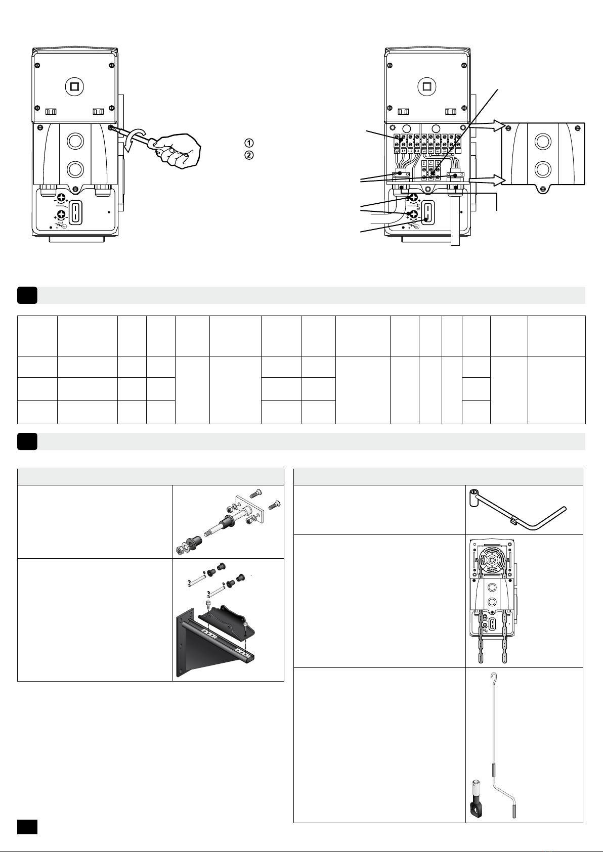
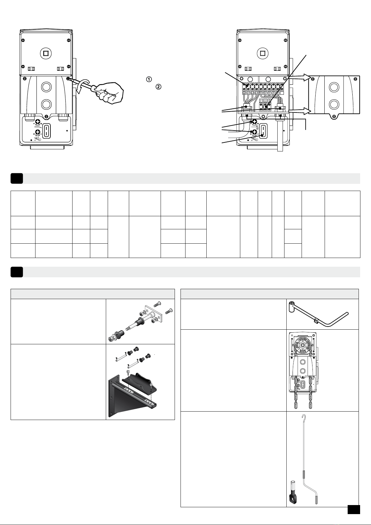
Une fois le branchement de l’alimentation électrique effectué, remettre
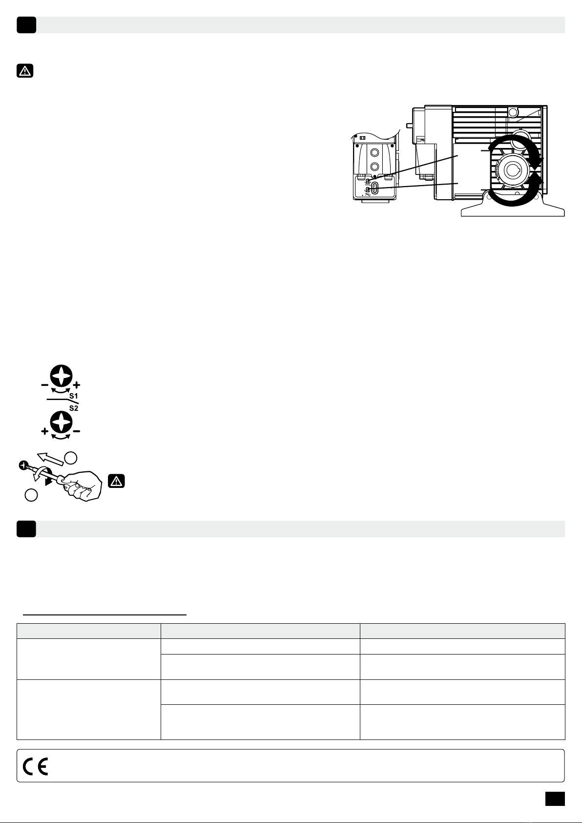
en place le couvercle connecteur :
- Resserrer les 3 vis.
- Mettre l’installation sous tension.
indiquant S1 et S2.
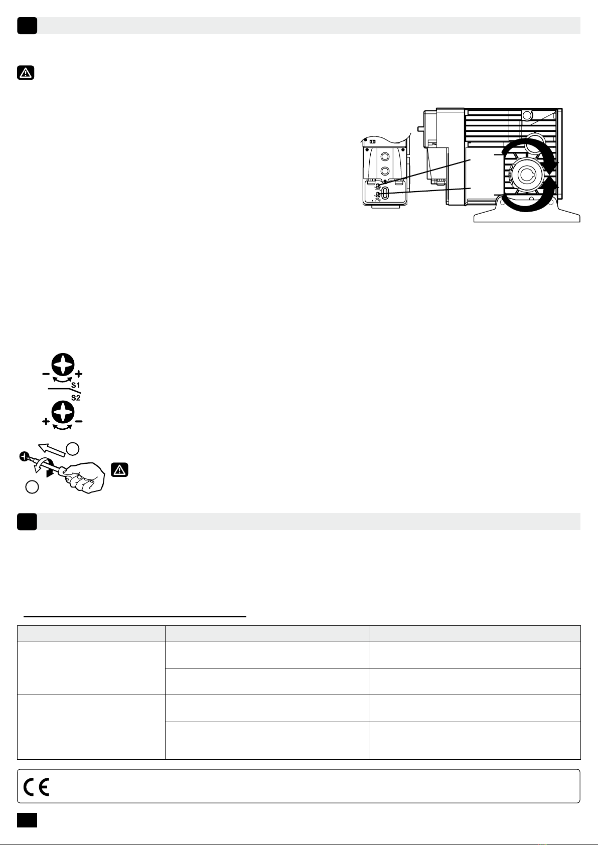
- Appuyer sur le S1 de l’interrupteur de réglage du moteur (en haut).
- Renouveler l’opération pour le S2.
Si l’axe de sortie tourne dans le sens opposé à celui désiré :
- Relâcher immédiatement le bouton.
- Couper l’alimentation.
- Inverser indifféremment 2 phases sur le bornier de puissance.
Actionner ensuite la montée du rideau par la boîte à clé. Si le moteur ne tourne pas dans le sens désiré :
- Relâcher immédiatement le bouton.
- Couper l’alimentation.
situe pas à la position désirée, enfoncer la vis correspondant au sens choisi (S1 ou S2) avec un
tournevis et :
- Pour augmenter la course : Pousser et tourner dans le sens « + ».
- Pour diminuer la course : Pousser et tourner dans le sens « - ».
Recommencer les réglages après dégagement de la butée.
S1
S2
SENS 1
SENS 2
1
2
MAINTENANCE
7
Le SIMUBOX a été conçu avec soin et ne demande aucun entretien particulier. Il est toutefois obligatoire de l’installer
Tout démontage du couvercle du carter entraîne l’annulation de la garantie.
Nous consulter pour tout fonctionnement autre que la motorisation des grilles et rideaux enroulables.
Par la présente, SIMU SAS F-70103 GRAY déclare que le produit couvert par ces instructions et utilisé comme indiqué dans ces instructions, est conforme aux exi-
gences essentielles des Directives Européennes applicables et en particulier à la Directive Machine 2006/42/EC et à la Directive CEM 2014/30/EU. Le texte complet
de la déclaration de conformité à l’UE est disponible sur www.simu.com. Fabrice GLORIEUX, directeur général, GRAY, 04/2018.
FR 5/5
- Astuces et conseils d’utilisation :
PROBLÈMES CAUSES POSSIBLES SOLUTIONS
Le produit motorisé ne
fonctionne pas.
La motorisation est au thermique. Attendre que la motorisation refroidisse.
Le système de manoeuvre de dépannage
est actif.
de la désactiver.
Le produit motorisé s’arrête en
plus.
de sécurité. Appeler votre personnel de maintenance
pour inspection de l’installation.
Suite à l’utilisation de la manoeuvre de
enclenché.
faire tourner le tube de 30° et désenclencher

SIMU S.A.S. au capital de 5 000 000 € - Z.I. Les Giranaux - BP71 - 70103 ARC-LÈS-GRAY CEDEX - FRANCE - RCS VESOUL B 425 650 090 - SIRET 425 650 090 00011 - n° T.V.A CEE FR 87 425 650 090
SIMUBOX 220/12 EI (three-phase)
SIMUBOX 300/12 EI (three-phase)
SIMUBOX 430/08 EI (three-phase)
5141057C
EN - TRANSLATION OF THE
ORIGINAL MANUAL
This manual applies to all three-phase SIMUBOX EI motors regardless of the torque/speed versions. Mandatory
instructions to be followed by the motor and building automation professional installing the motor.
SCOPE
Three-phase SIMUBOX EI motor is intended to activate curtains or grilles for commercial and industrial premises.
For information on the compatibility of the motor with the product to be powered and the accessories, contact the
manufacturer of the product to be powered or SIMU.
LIABILITY
Read this installation and user manual carefully before installing and using the three-phase SIMUBOX EI
motor. In addition to the instructions described in this manual, you must also follow the instructions detailed in the
attached document “ICC Safety Instructions”.
Any use of three-phase SIMUBOX EI motors outside the scope of application described above is prohibited. This
releases SIMU from all liability and warranty obligations, as does failure to comply with the instructions in the manual
as well as instructions in “ICC Safety Instructions”.
The installer must inform their customers of the conditions for using and maintaining the three-phase SIMUBOX EI
motor and must provide them with the use and maintenance instructions as well as the “ICC Safety Instructions”,
after installing the three-phase SIMUBOX EI motor. All operations on the three-phase SIMUBOX EI motor, including
After Sale Service, require the intervention of a motor and building automation professional. If you have any doubt
while installing the three-phase SIMUBOX EI motor or if you require any additional information, get in touch with a
SIMU contact or visit the website www.simu.com.
COMPATIBILITY
Three-phase SIMUBOX EI motors have been made to be exclusively controlled by unstable key switches offered in
the SIMU catalogue.
TECHNICAL CHARACTERISTICS
1
1.1 - Dimensions
S1
S2
square of 10
Ø 30
45
EN
1/5

EN 2/5
1 2
1.2 - Front face description
End limit adjustment screws Inputs for
command
connection and
power supply
S1
S2
Extra switches
MOTOR RANGE
2
ACCESSORIES
3
Manual override
Short crank (included)
Override by chain
• 10 meter chain
S1
S2
Override with long crank
• Ring
• Crank handle with hook
For mounting
Installation with block rod
Installation with bracket +
mounting bracket
Adjustment switch
Terminal plug
power supply connection
command connection
Traction stops
Reference Description Torque
(Nm)
Speed
(rpm)
Shaft
diameter
(mm)
Power supply
Power
consumption
(W)
Intensity
at nominal
torque
(A)
Operating time
(min)
Nb
cycles /
hour
IP Weight
(Kg)
Limit
switch
capacity
(turns)
Operating
temperature
2009130 SIMUBOX
220/12 EI TRI 220 12
30 400V 3~ -
50Hz
850 1.6
10 15 0.9 44
17
25 -10°C - + 40°C
2009388 SIMUBOX
300/12 EI TRI 300 12 1050 1.9 17
2009131 SIMUBOX
430/08 EI TRI 430 08 1100 2.1 18

EN
3/5
Unstable wired controls
Universal key switch in
unstable mode
(with or without branding)
Unstable key switch Unstable waterproof key
switch Waterproof rotary push
button
iFor any other key switch, please contact your SIMU interlocutor.
• 1. Simubox
• 2. Block rod
• 3. Plate motor side
• 4. Adjustable bobbin with key
• 5. Adjustable bobbin with key
• 6. Plate opposite side
• 7. Safety brake
Installation with block rod :
3
4
2
5
6
7
• 1. Simubox
• 2. Mounting bracket
• 3. Bracket
• 4. Adjustable bobbin with key
• 5. Adjustable bobbin with key
• 6. Braket opposite side
• 7. Safety brake
Installation with bracket :
MOTOR INSTALLATION
4
4.1 - For grilles and shutters
Do not forget to grease the keyed shaft of the coil before mounting the motor.

EN 4/5
4.2 - Mounting of chain manual override
S1
S2
S1
S2
1. Remove the chain cover by
unscrewing the 4 screws.
2. Install the chain.
3. Pass the chain links in the
chain guide and in the notched
wheel by introducing them in.
4. Replace the cover.
WIRING
5
Three-phase SIMUBOX EI motors have been made to be exclusively wired with 1.5 mm² diameter cables for the
power supply connection and with 0.75 mm² diameter cables for the command connection.
Attach the cables to prevent contact with moving parts.
- The installer must ensure that the installation of the motorization complies with the electrical installation instructions
in force in the country of commissioning.
- Always make a loop on the power cable to prevent water penetration into the actuator.
- Cables passing through a metal wall must be protected and insulated by a sleeve or sheath.
- The motor casing must be connected to a rigid conduit.
- Use the traction stop.
- The connection of the power supply conductors must only be made after installing the motor on its support.
- Cables have to be stripped on 8 mm.
Installation diagram:
SAFETY BRAKE
1I
PI
2I
4
3
2
1
5
KEYSWITCH
1
Cde S1
Cde Com
Cde S2
Secu Ext
Secu Ext
2
3
4
5
POWER SUPPLY
1 2
3
4
iTraction stop has to be used.
Secu Ext inputs have to be wired in order to
operate the motor.
There are 2 auxiliary contacts available which allow,
for example, to know if the door is in open or closed
position.
Outputs are made on a 3 terminal connector which is
Outputs of auxiliary contacts on 3 terminal connector :
• 1 terminal Ri S1 for S1
• 1 terminal Ri Com for common
• 1 terminal Ri S2 for S
Type of output : dry contacts normally open
Capacity : 1A under 24Vdc

EN
5/5
END-LIMIT ADJUSTMENT
6
6.1 - Checking rotation direction
It is essential to check the rotation direction of the motor to ensure proper operation of the limit switches.
Once the power supply is connected, replace the wiring cover :
- Tighten the 3 screws
- Switch on the installation
- Spot the S1/S2 arrows placed around the shaft.
- Push on the S1 of the motor switch (up).
- Axis has to turn in the S1 way.
- Repeat the operation with S2.
If the output shaft is rotating in the opposite direction to the one
required :
- Immediately release the switch.
- Switch off the supply
- Interchange 2 phases.
- Switch on again and check the rotation direction.
Then move the shutter with the keyswitch. If the operation is reversed :
- Immediately release the switch.
- Switch off the supply
- Revert wiring of Cde S1 and Cde S2
- Switch on again and check the rotation direction.
6.2 - End limit adjustment
Use the switch on the motor to operate the curtain. If the limit switch is not in the desired position,
push in the screw corresponding to the chosen direction (S1 or S2) with a screwdriver and :
- To increase the number of turns: Push and turn in the”+” direction.
- To decrease the number of turns: Push and turn in the”-” direction.
the settings after releasing the stop.
S1
S2
SENS 1
SENS 2
1
2
MAINTENANCE
7
SIMUBOX has been carefully designed and requires no special maintenance. However, it must be installed away
from splashing water. It is lubricated for life, the special lubricant should never be changed.
Any removal of the housing cover will void the warranty.
Consult us for any operation other than the motorization of grids and roll-up curtains.
Do not forget to grease the keyed shaft of the coil before mounting the motor.
SIMU SAS F-70103 GRAY hereby declares that the product covered by these instructions and used as indicated in these instructions, complies with the essential
requirements of the applicable European Directives and in particular with the Machine Directive 2006/42/EC and the EMC Directive 2014/30/EU. The full text of the EU
Declaration of Conformity is available at www.simu.com. Fabrice GLORIEUX, Director General, GRAY, 04/2018.
- Tips and recommendations for installation:
PROBLEMS POSSIBLE CAUSES SOLUTIONS
The motorised product does
not operate.
The overheating protection on the drive has
been activated. Wait for the drive to cool down.
The manual override system is active. Release the troubleshooting maneuver to
deactivate it.
The motorised product stops
at the end limit and no longer
operates.
The motor is stopped at its security end
limit. Call your maintenance staff to inspect the
installation.
Following the use of the manual override
system, the security end limits device is
activated.
Use the manual override system to turn the
tube 30° and deactivate the security end
limits device.

AR 1/5
SIMU S.A.S. au capital de 5 000 000 € - Z.I. Les Giranaux - BP71 - 70103 ARC-LÈS-GRAY CEDEX - FRANCE - RCS VESOUL B 425 650 090 - SIRET 425 650 090 00011 - n° T.V.A CEE FR 87 425 650 090
SIMUBOX 220/12 EI
SIMUBOX 300/12 EI
SIMUBOX 430/08 EI
5141057C
SIMUBOX EI
SIMUBOX EI
.SIMU
SIMUBOX EI
."ICC
SIMUSIMUBOX EI
."ICC
SIMUBOX EI
SIMUBOX EISIMUBOX EI"ICC
SIMUBOX EI
www.simu.com.SIMU
.SIMUSIMUBOX EI
1
S1
S2
10 ﻊﺑرﻣ
Ø 30
45
- AR

AR
2/5
2
3
10
S1
S2
S1
S2
1 2
(A)
IP
2009130
SIMUBOX
220/12 EI TRI
22012
30
- ~3400
50
8501.6
10150.944
17
25
10 -
40+
2009388
SIMUBOX
300/12 EI TRI
3001210501.917
2009131
SIMUBOX
430/08 EI TRI
4300811002.118

AR 3/5
SIMU i
Simubox .1 •
2 •
3 •
4 •
5 •
6 •
7 •
3
4
2
5
6
7
Simubox .1 •
2 •
3 •
4 •
5 •
6 •
7 •
4

AR
4/5
5
SIMUBOX EI
8
نﺎﻣأ ﺢﺑﻛﻣ
1I
PI
2I
4
3
2
1
5
ﻲﺳﯾﺋرﻟا حﺎﺗﻔﻣﻟا
1
Cde S1
Cde Com
Cde S2
Secu Ext
Secu Ext
2
3
4
5
ﺔ
ﻗﺎطﻟا تادادﻣإ
S1
S2
S1
S2
1
2
3
4
12
3
4
i
SECU Ext
2
3
:3
Ri S1 for S11•
Ri Com for common1•
Ri S2 for S1•
24Vdc1A

AR 5/5
6
S1 / S2
S1
.S1Axis
.S2
2
Cde S2Cde S1
S2S1)
S1
S2
1 هﺎﺟﺗﻻا
2 هﺎﺟﺗﻻا
1
2
7
SIMUBOX
SIMU SAS F-70103 GRAY
.04/2018 ,GRAY ,Director General ,Fabrice GLORIEUX .www.simu.com2014/30/EUEMC2006/42/EC
: -
30

www.simu.com
This manual suits for next models
5
Table of contents
Languages:
Popular Gate Opener manuals by other brands

GFA
GFA ELEKTROMAT FT 80.5 FU-45,00 installation instructions

Maximum Controls
Maximum Controls MAX SUPER ARM 2300 manual

Allstar
Allstar RSLG3500 owner's manual

DITEC
DITEC OBBI3BH Maintenance manual

MFZ Ovitor
MFZ Ovitor AS 210 B operating instructions

Portamatik
Portamatik BETA400 User's and installer's manual