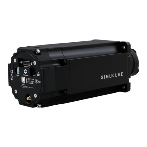
Simucube 2 Sport User manual

Simucube 2
Sport / Pro / Ultimate
User Guide
Version 3.0
July 31st, 2020

User Guide changelog
Version
Date
Changes
1.0
2019/06/06
Initial release
2.0
2019/08/14
SQR rev 2 update, external antenna
2.1
2019/09/04
Profile settings and templates explained,
simple profiles mode (not released yet),
additional troubleshooting tips
2.2
2019/09/23
Improved wireless wheel led information
2.3
2019/10/01
Added disclaimers about product
appearance, note about exposure to
direct sunlight
2.4
2019/10/30
Copied disclaimer from Accessory port
user guide. Changed idle and standby
behaviour, added title “Idle and standby”
2.5
2019/11/01
Moved standby chapter to better
location.
2.6
2019/11/06
Added standby mode LED description.
2.7
2020/04/24
Text formatting fixes.
Added warning that Ultimate version is
for professional use only.
Added a guide for assembling and
disassembling the SQR wheel side.
Changed pictures in SQR guide with
correct bolts.
Fixed incorrect SQR assembly option (2)
Added: indoor use only.
2.8
2020/06/02
Changed Bumpstop functionality
description. Changed Wireless Wheel
disconnect descriptions. Updated UI
images. Added note about discarding the
product. Added warning about handeing
the Ultimate PSU. Added recycling. Added
ultimate psu ip30 rating. Edited
operating environment. Added warranty
address.
2.9
2020/06/05
Add note about simulator/game updates.
2.10
2020/07/08
Changed company address. Style fixes.
Spelling.
3.0
2020/07/31
Release publish
Previous published versions of the User Guide can be downloaded from here:
https://granitedevices.com/wiki/File:Simucube_2_User_Guide.pdf

Warnings and guidelines for safe operation
•Simucube 2 Ultimate is intended for professional use only. Usage under other conditions is under
user’s own responsibility.
•Do not grab, hold or insert fingers, etc objects to the rotating parts in a way where letting go
immediately is not always possible.
•Do not operate Quick Release when the device is powered ON and connected to a PC.
oAlways disable torque by pressing Torque off button before removing or attaching wheel.
oDo not release Torque off button unless Quick Release has been securely clamped with Quick
Release pin.
•Do not set torque level higher than the level user can safely hold with a single hand grip
•If torque gets too high to control safely, let both hands off the wheel and press the Torque off button
•Preventing motion by the means of True Drive or simulator software are not reliable ways to prevent
motion
•Device user must be an adult and physically and mentally fit person
•Usage of the device is allowed only by an instructed person who understands and follows the above
safety instructions
•If the device becomes damaged in any way, stop using it immediately and contact the reseller
•Using the vibration and force feedback may cause damage to your health
•Do not open the casing of the device or the power supply. There are no user serviceable parts inside,
and disassembling will void manufacturer’s warranty.
•Do not use the device with a power source other than the power supply packaged with the Simucube
2 or received from an authorized reseller. Do not operate SC2 Pro model with only one power supply
connected and powered.
•Do not use the device with any cables other than the cables packaged with the Simucube 2 or received
from an authorized reseller
•The Simucube Accessory port is a female D15 connector on the back of the device. Its signal levels are
from 0 to 5 Volts. Do not connect any unknown devices to this connector. The port is not a serial port
connector although the mechanical connector is the same as a 15-pin serial port.
•This product has magnets which may interfere with pacemakers, defibrillators and programmable
shunt valves or other medical devices. Do not put this product close to these medical devices and the
person who use any of these medical devices. Consult your doctor before using this product if you have
any concerns.
•Simucube 2 Ultimate power supply is not intended to withstand physical stress. Do not damage or
mishandle the power supply.

•Operating environment:
o15°C –30°C room temperature, non-condensing humidity
oDo not expose the Simucube 2 device to direct sunlight.
oIndoor use only.
oSimucube 2 Ultimate power supply is IP30 rated.
•Rotating high torque parts:
oShaft torque up to 32 Nm
oShaft rotation speed up to 360 RPM
oShaft mechanical power up to 600W
•Hazard of entangling to rotating parts:
oPull force may exceed 130 kg / 270 lbs / 800 N when wire, rope, hair or similar object tangles
on 5 cm / 2" spool diameter (such as output shaft of the device)
•Hot surface:
oDevice surface temperature may reach 70⁰C or 158⁰F.
oSudden rotation / vibration
•Device may start producing motion unexpectedly
Safe usage instructions
A. Mount device securely to a rigid platform before use. Fix Simucube 2 to a proper table
mount or a racing rig that is Simucube 2 compatible with all four fixings screws that are
included. Do not use other types of fixings. Never operate the product without fixing it first
as instructed in this User Guide.
B. Read this user guide completely before installing or operating the device.
C. Test functioning of the Torque off button before each usage session.
D. Keep children away from the device.
E. Do not attempt to stop freely rotating parts by grabbing.
F. Always use the Torque off button or power off the device to stop and prevent motion.
G. Instruct other users of the device about the safe usage.
H. Keep hair, cables, clothing and other entangling items clear from the rotating parts.

Technical Datasheet
SIMUCUBE 2 Sport
SIMUCUBE 2 Pro
SIMUCUBE 2 Ultimate
Motor
Direct Drive
optimized ultra low
torque ripple motor
High response speed Direct
Drive optimized ultra low
torque ripple motor
Maximum response speed, low
inertia, Direct Drive optimized
ultra low torque ripple motor
Simucube
Wireless Wheel™
support
Included
Included
Included
Simucube Quick
Release™
Included
Included
Included
Max torque *
17 Nm
25 Nm
32 Nm
Max torque slew
rate
4.8 Nm/ms
8.0 Nm/ms
9.5 Nm/ms
Angle sensor
22 bit absolute
22 bit absolute
24 bit Hiperface
Torque Off button
Standard (Premium
optional)
Standard (Premium
optional)
Premium (with remote power
switch)
Power supply
280 W
2 x 280 W
1000 W
Wheel base
dimensions incl.
SQR™
130 x 130 x 250 mm
130 x 130 x 270 mm
115 x 115 x 310 mm
Mounting holes
M8 x 4 pcs threaded
hole
M8 x 4 pcs threaded hole
9 mm dia x 4 pcs through hole
Mounting hole
pattern dia
145 mm
145 mm
130 mm
Flange centering
hole dia
110 mm
110 mm
110 mm
Wheel base
weight
8.0 kg
11.1 kg
11.3 kg
Standard
warranty
24 months
24 months
60 months
3-D drawings of the Simucube 2 products can be found from the Simucube website at
http://www.simucu.be/

What’s included (Simucube 2 Sport and Pro models)
Figure 1 Simucube 2 Sport and Pro hardware
1. Simucube 2 wheel base
2. Power supply (1 pcs for Sport, 2 pcs for Pro)
3. Power supply AC-cable (EU) (1 pcs for Sport, 2 pcs for Pro)
4. Torque off button and cable (Sport and Pro)
5. USB cable
6. Fixing hardware for the wheel base and SQR
7. SQR pin
8. Wheel side SQR
9. 30mm Spacer
10. Adapter for 70mm wheels
11. External antenna for Simucube Wireless Wheel signal reception
Disclaimer:
Simucube 2 product appearance might differ from the illustrations on this User Guide and from
the product pictures at the http://www.simucu.be website.

What’s included (Simucube 2 Ultimate)
Figure 2 Simucube 2 Ultimate hardware
1. Simucube 2 wheel base
2. Power supply
3. Power supply AC-cable
4. Power supply DC-cable
5. Premium torque off button cable
6. USB cable
7. SQR pin
8. Wheel side SQR
9. 30mm Spacer
10. Adapter for 70mm wheels
11. Premium torque off button
12. Fixings for wheel base and SQR
13. External antenna for Simucube Wireless Wheel signal reception
Disclaimer:
Simucube 2 product appearance might differ from the illustrations on this User Guide and from
the product pictures at the http://www.simucu.be website.

Getting started
Mounting the motor on the simulator
Simucube 2 must always be rigidly mounted on the simulator rig for user safety.
Mounting option 1
Simucube 2 can be mounted with separate bracket that can convert the front mount to a
horizontal platform (table) mounting as in Figure 3. Mounting brackets be found from Simucube
resellers listed on https://www.simucu.be website.
Figure 3 Mounting Simucube 2 using a mounting bracket.
Mount Simucube 2 as shown in Figure 3. Sport and Pro models are mounted with 30mm M8 bolts
with 1.25mm thread pitch (1) and M8 flat washers (2). Simucube 2 Ultimate is mounted through-
the motor flange with 40mm M8 bolts (1), M8 flat washers (2) and M8 locking nuts (3).

Mounting option 2
Simucube 2 can be mounted by utilizing a front mount bracket found on many simulator rigs as
shown in Figure 4.
Figure 4 Mounting Simucube 2 on a simulator rig front mount bracket.
Mount Simucube 2 as shown in Figure 4. Sport and Pro models are mounted with 30mm M8 bolts
with 1.25mm thread pitch (1) and M8 flat washers (2). Simucube 2 Ultimate is mounted through-
the motor flange with 40mm M8 bolts (1), M8 flat washers (2) and M8 locking nuts (3).

Wiring
Read and understand this chapter fully. Do not operate the product if you haven’t fully read
or understood this document. Check that main power switch at the back is off and all cables
are unplugged before proceeding.
Connect the cables as indicated in figures 5 and 6. Important: always connect the AC power
supplies first to Simucube (connection 3) and only then to AC mains socket (4).
Figure 5 Simucube 2 Sport and Pro wiring diagram.
Note: Simucube 2 Sport has one power supply, and Simucube 2 Pro has two power supplies.
Figure 6 Simucube 2 Ultimate wiring diagram. Use Simucube 2 Ultimate only in a professional environment.

Antenna installation
(1) Locate the antenna connector at the back of your Simucube 2 wheel base.
(2) Take the supplied antenna (Disclaimer: use ONLY the supplied antenna) and insert it into the
antenna connector. Make sure you are inserting it in a straight orientation. Gently twist the
knurled surface at the end of the antenna in clockwise direction approximately 3 turns. DO NOT
use any tools in the installation, only screw the antenna in place with your fingers.
You can now use the joint in the antenna to adjust antenna so that it is not in the way of other
connectors/obstacles. In normal usage the orientation has little effect to received signal strength.
The signal strength can be checked in the True Drive software.

Checklist for the first use
1. Connect remote Torque off button box to Simucube 2’s TORQUE OFF connector.
2. Connect USB cable from Simucube 2 to PC.
3. Connect power supply/supplies to Simucube 2 POWER IN connectors.
Important:
1. Always connect POWER IN connector(s) on
Simucube 2 first before connecting power supply
to the AC outlet.
2. Both power supplies must be used for Simucube
2 Pro.
3. Simucube 2 Ultimate is to be used only in a
professional environment.
4. Connect power supply/supplies to 110 - 240 V AC outlet with protective earth (PE).
5. Fix steering wheel (not included) to Simucube Quick Release™ (SQR™). If required, install
Spacer and/or 70 mm Adapter between the SQR wheel side part and the wheel.
6. Download and install True Drive software from https://simucu.be website. This product
will not fully operate without installing the software for safety reasons.

Simucube Quick Release (SQR) User Guide
SQR –Wheel side assembly
Figure 7 SQR assembly options
The included wheel side SQR (Simucube Quick Release) system can be assembled in multiple
configurations to best suit your wheel and button box combination.
Standard configurations (Figure 7) include (1) 50.8 mm PCD (pitch circle diameter) front
mounting without the spacer, (2) 50.8 mm PCD front and back mounting with the spacer and
(3+4) 70 mm PCD front and back mounting.

SQR –50.8 mm PCD front mounting, no spacer
It is possible to use the SQR without a spacer, but the use of the spacer is recommended as it gives
the user more space to use the locking pin. To attach the wheel side plate to your wheel, use
suitable M5 screws and washers (3 or 6 screws depending on your wheel type) from the included
ones or use your own if suitable length is not found. In case you have a need to find longer/shorter
screws, the correct screw thread type is M5 size with 0.8 mm pitch.

SQR –50.8 mm PCD front and rear mounting, with spacer
To rear-mount your wheel (if you have threads in the rear of your wheel/button box), you will
need 3 or 6 M5 screws with a length depending on your wheel and button box thickness and 1
washer per screw. Align the four middle threaded holes as in the image and attach the screws in
the order as illustrated.
Use four of the included 10mm long M5 screws and 4 washers to attach the wheel side plate to
the spacer as illustrated. Note: Do not use excessive torque to avoid damaging the threads in the
SQR aluminum parts.

To front-mount your wheel, you will need 3 or 6 M5 screws and a washer per screw. The right
length for these screws is approximately 35-39mm + the thickness of your wheel and button box
since the screws attach to the threads in the wheel side plate.
Use four of the included 10mm long M5 screws and 4 washers to attach the wheel side plate to
the spacer as illustrated. Align the four middle threaded holes as in the image and attach the rest
of the screws as illustrated.
Completed SQR setup for 50.8 mm PCD wheel.

SQR –70 mm PCD front and rear mounting, with spacer
To front-mount your wheel, you need 6 M5 screws with a length depending on your wheel and
button box thickness, 2 washers per screw and 1 locking nut per screw. Align the eight middle
threaded holes as in the image and attach the screws in the order as illustrated.
To rear-mount your wheel (if you have threads in the rear of your wheel/button box), you will
need 6 M5 screws with a length depending on your wheel and button box thickness and 1 washer
per screw. Align the eight middle threaded holes as in the image and attach the screws in the
order as illustrated.

In both cases use four of the included 25 mm long M5 screws and 4 washers to attach the wheel
side plate to the spacer as illustrated. Note: Do not use excessive torque to avoid damaging the
threads in the SQR aluminum parts.
In both cases use four of the included 10 mm long M5 screws and 4 washers to attach the wheel
side plate to the spacer as illustrated. Note: Do not use excessive torque to avoid damaging the
threads in the SQR aluminum parts.

Completed SQR setup for 70 mm PCD wheel.
SQR –70 mm PCD with no spacer
Due to the diameter of the wheel side SQR plate, use of the 70 mm adapter without the spacer is
not possible with the included hardware.

SQR –Motor side assembly
When installing the SQR (Simucube Quick Release) system ensure that the motor shaft diameter
is compatible with the SQR.
The SQR motor side can be disassembled and re-installed in case of slipping or other problems
relating to tightness, or if for some reason the black hub has slipped too close to the motor and
appears to be touching it.
SQR –Quick Release Pin adjustment
The tightness of release pin can be adjusted. Video guide: youtube.com/watch?v=YYKkb5Ioadg
Motor side disassembly
Open the three bolts on the top of SQR and remove the motor side plate.
If you do not want to lose the SQR position, draw some markings to remember the SQR position
related to the motor shaft.
Open the four cone clamp bolts and remove the cone clamp and the SQR outer tube. If the cone
clamp can’t be removed after opening the four bolts, it can be opened by screwing one or two
cone clamp bolts to the two empty threaded holes.
This manual suits for next models
2
Table of contents
Other Simucube Video Game Controllers manuals
