manuals.online logo
Brands
  1. Home
  2. •
  3. Brands
  4. •
  5. SImx
  6. •
  7. Fan
  8. •
  9. SImx Manrose Classic XP125 User manual

SImx Manrose Classic XP125 User manual

This manual suits for next models

4

Other SImx Fan manuals

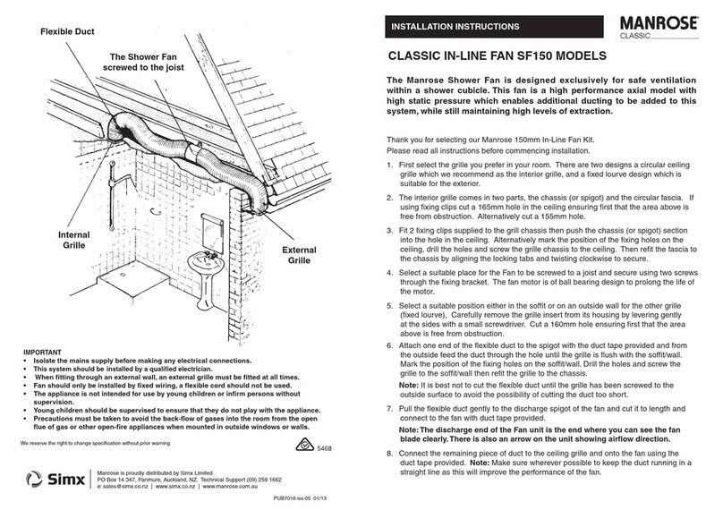
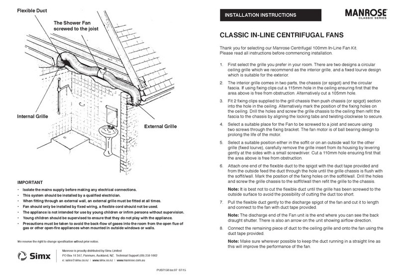
SImx Manrose Classic Series User manual

SImx

SImx Manrose Classic Series User manual

SImx Manrose Classic Series User manual

SImx

SImx Manrose Classic Series User manual

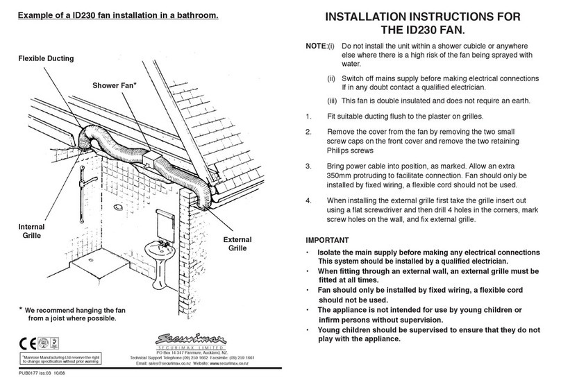
SImx MANROSE ID230 Series User manual

SImx

SImx MANROSE ID230 Series User manual

SImx Manrose User manual

SImx

SImx Manrose User manual

SImx MixFlo Pro Series User manual

SImx

SImx MixFlo Pro Series User manual

SImx Manrose SF150 User manual

SImx

SImx Manrose SF150 User manual

Popular Fan manuals by other brands

Minka Group minkaAire Wave F843 instruction manual

Minka Group

Minka Group minkaAire Wave F843 instruction manual

Airflow Adroit DV50 instruction manual

Airflow

Airflow Adroit DV50 instruction manual

Vornado 270 Series owner's guide

Vornado

Vornado 270 Series owner's guide

comfort air TH-10D instruction manual

comfort air

comfort air TH-10D instruction manual

Livoo DOM386 instruction manual

Livoo

Livoo DOM386 instruction manual

Holmes BLIZZARD HAOF-90 owner's guide

Holmes

Holmes BLIZZARD HAOF-90 owner's guide

Taurus GRECO 16 ELEGANCE manual

Taurus

Taurus GRECO 16 ELEGANCE manual

Quorum PINNACLE installation instructions

Quorum

Quorum PINNACLE installation instructions

Monte Carlo Fan Company 3DIR58RBD-V1 Owner's guide and installation manual

Monte Carlo Fan Company

Monte Carlo Fan Company 3DIR58RBD-V1 Owner's guide and installation manual

Craftmade UH52 installation guide

Craftmade

Craftmade UH52 installation guide

Jocel JVA030658 instruction manual

Jocel

Jocel JVA030658 instruction manual

MIKA MFB1211/GR user manual

MIKA

MIKA MFB1211/GR user manual

Harbor Breeze RLG52NWZ5L manual

Harbor Breeze

Harbor Breeze RLG52NWZ5L manual

Allen + Roth L1405 instruction manual

Allen + Roth

Allen + Roth L1405 instruction manual

ViM KUBAIR F400 ECOWATT Technical manual

ViM

ViM KUBAIR F400 ECOWATT Technical manual

HIDRIA R10R-56LPS-ES50B-04C10 user guide

HIDRIA

HIDRIA R10R-56LPS-ES50B-04C10 user guide

BLAUBERG Ventilatoren CENTRO-M 100 L user manual

BLAUBERG Ventilatoren

BLAUBERG Ventilatoren CENTRO-M 100 L user manual

Triangle Engineering HEAT BUSTER SPL Series owner's manual

Triangle Engineering

Triangle Engineering HEAT BUSTER SPL Series owner's manual

manuals.online logo
manuals.online logoBrands
  • About & Mission
  • Contact us
  • Privacy Policy
  • Terms and Conditions

Copyright 2025 Manuals.Online. All Rights Reserved.

Diagram 2
Diagram 2A
We reserve the right to change specification without prior warning
Manrose is proudly distributed by Simx Limited
PO Box 14 347, Panmure, Auckland, NZ. Technical Support (09) 259 1662
e: [email protected] | www.simx.co.nz | www.manrose.co.nz
(The ‘new’ ball bearing designed motors provide an extended lifetime of operation)
NOTE: (i) The fan is to be installed so that the blades are 2.1m above the floor. For best results
this Extractor Fan should be fitted as high on the wall as possible, or if preferred, on
the ceiling.
(ii) Do not install the unit within a shower cubicle. Use our shower fan models no’s
SF125S or SF125T.
(iii) Switch off mains supply before making electrical connections. This system should
be installed by a qualified electrician.
(iv) This fan is double insulated and does not require an earth.
(v) When installing fan through an external wall, an external wall grille must be fitted
at all times.
1. Cut a 140mm diameter hole in the wall. If the fan is to be fixed onto the ceiling ensure that
the hole is between the joists.
2. Fit 125mm ducting flush to the plaster.
3. Remove the cover from the fan by simply unclipping the fascia. The front cover screw and
plug are conveniently located within the fan housing as shown in diagram 1 & 2.
4. Hold the body of the fan against the wall or ceiling and mark the four screw holes and the
cable entry.
IMPORTANT: Ensure that the fan is square on wall the or ceiling.
5. Bring power cable into position, as marked. Allow an extra 230mm (9”) protruding to
facilitate connection.
Fan should only be installed by fixed wiring, a flexible cord should not be used.
6. If an XP125 kit - Select a suitable position on the outside wall for the weatherproof cowl.
Carefully remove the cowl from its housing by levering gently at the sides with a small
screwdriver. Cut a 140mm hole ensuring first that the area is free from obstruction.
7. Wiring of Standard Model XF125S and XP125S (see Diagram 2A).
(For remote switch operation).
The fan can be connected to the light switch so that the fan will start when the light is switched
on. The fan should not be accessible to a person using either the shower or the bath.
NOTE: All wiring must be fixed securely and the cable to the fan should be a minimum of
1mm2in section. All wiring must comply with current Regulations. This system should be
installed by a qualified electrician.
PUB7007 2212
MANROSE CLASSIC XF/XP125 CEILING/WALL
EXTRACTOR FANS
INSTALLATION INSTRUCTIONS CLASSIC SERIES
Rotary adjuster
for time delay
Diagram 2B
Diagram 1
IMPORTANT
FAN MUST BE
INSTALLED THIS
WAY UP WHEN
MOUNTED ON WALL
Specifications:
Model: NZNVF120SBB; NZNVF120TBB
Electrical: 220-240V~50Hz
Fan Wattage: 25W
Max Temp: 40˚C
Airflow: 36l/s (130m3/hr)
Max Pressure: 35 Pa
Sound Volume: 41 dB(A)
IP Rated: IP44 (except pullcord model IP24)
Diagram 1A
8. Wiring of Pullcord Models XF125P and XP125P (see Diagram 1).
(This model is unsuitable for ceiling mounting).
This fan has its own integral pullcord on/off switch. The fan should not be accessible to a
person using either the shower or the bath.
NOTE: All wiring must be fixed securely and the cable to the fan should be a minimum
of 1mm2in section. All wiring must comply with current Regulations. This system should
be installed by a qualified electrician.
9. Wiring of Timer Model XF120T and XP120T
See Diagram 2 & 2A.
The fan can be connected to the light switch so that the fan will start when the light is
switched on. When the light switch or pullcord is switched off the fan will run for between
20 sec & 30 minutes (pre-set to 1 minute). The fan should not be accessible to a person
using either the shower or the bath.
Timer Adjustment XF120T & XP120T only.
T
his time delay can be adjusted by firstly switching off the power to the fan and removing the
fascia. Locate the rotary adjuster as shown in Diagram 2. The serrated adjuster wheel
can be rotated using a thumbnail to adjust the timer setting.
+ = Rotate to the right to increase the time (indicated by + on the diagram)
- = Rotate to the left to decrease the time (indicated by - on the diagram)
Only adjust with power switched off.
NOTE: All wiring must be fixed securely and the cable to the fan should be a minimum of
1mm2in section. All wiring must comply with current Regulations. This system should be
installed by a qualified electrician.
For timer adjustment see diagram 2B min 30 secs, max 30 mins.
• Isolate the mains supply before making any electrical connections.
This system should be
installed by a qualified electrician.
• Fan should only be installed by fixed wiring, a flexible cord should not be used.
• The appliance is not intended for use by young children or infirm persons without supervision.
• Young children should be supervised to ensure that they do not play with the appliance.
• Exhaust fans may adversely affect the safe operation of burning gas or other fuels
(including those in other rooms) due to back flow of combustion gases. These gases
can potentially result in carbon monoxide poisoning. After installation of an exhaust fan
such as a partition fan or a duct fan the operation of flued gas appliances should be
tested by a competent person to ensure that back flow of combustion gases does not occur.
IMPORTANT