Sinapsi EQUOBOX SIN.EQLC250 User manual

S I N AP S I S . r . l .
V i a d e l l e Q u e r c e 1 1 / 1 3
0 6 0 8 3 B a s t i a U m b r a ( P G ) I t a l y
T . + 3 9 075 8011604 F .+ 3 9 075 8014602
w w w . s i n a p s i t e c h . i t |i n f o @ s i n a p s i t e c h . i t
EQUOBOX SIN.EQLC250
M-Bus Level Converter
Adapter/Repeater
User Guide
Rev 1.0

E Q U O B O X S I N . E Q L C 2 5 0 –U s e r G u i d e R e v . 1 . 0
S I N A P S I S . r . l. | V i a d e l l e Q u e r c e 1 1 / 1 3 - 0 6 0 8 3 B A S T I A U M B R A ( P G ) –I t a l y
T . + 3 9 075 8011604 - F . + 3 9 075 8014602| w w w . s i n a p s i t e c h . i t -i n f o @ s i n a p s i t e c h . i t 2
TABLE OF CONTENTS
1. M-BUS OVERVIEW ........................................................................................................................................... 3
1.1 DESCRIPTION of the M-Bus System ..................................................................................................... 3
1.2 Addressing............................................................................................................................................... 3
1.3 Sizing the M-Bus System ....................................................................................................................... 4
1.4 BUS signal specifications ....................................................................................................................... 4
2. SIN.EQLC250 INSTALLATION ......................................................................................................................... 5
2.1 Description of the SIN.EQLC250 ........................................................................................................... 5
2.2 Operating modes of power supply ...................................................................................................... 6
2.3 Connection terminals............................................................................................................................. 7
2.4 Topology and connection of the M-Bus network............................................................................... 8
2.5 SIN.EQLC250 operation modes ............................................................................................................ 9
2.6Status LED.............................................................................................................................................. 10
2.7 Short circuit protection........................................................................................................................ 10
2.8 Firmware update .................................................................................................................................. 11
3. Troubleshooting............................................................................................................................................ 12
4. Technical features......................................................................................................................................... 13
E Q U O B O X S I N . E Q L C 2 5 0 –U s e r G u i d e R e v . 1 . 0
S I N A P S I S . r . l. | V i a d e l l e Q u e r c e 1 1 / 1 3 - 0 6 0 8 3 B A S T I A U M B R A ( P G ) –I t a l y
T . + 3 9 075 8011604 - F . + 3 9 075 8014602| w w w . s i n a p s i t e c h . i t -i n f o @ s i n a p s i t e c h . i t 3
1. M-BUS OVERVIEW
1.1 DESCRIPTION of the M-Bus System
The M-Bus (Meter Bus) system is a communication protocol compliant with the EN13757-2 standard.
The M-Bus System provides the following advantages:
•High level of data transmission security
•Low wiring costs
•Long distances without requiring repeaters
•Large number of central units
•Detection of both battery-powered and mains-powered devices
•Automatic device recognition
•Vast array of systems and components available
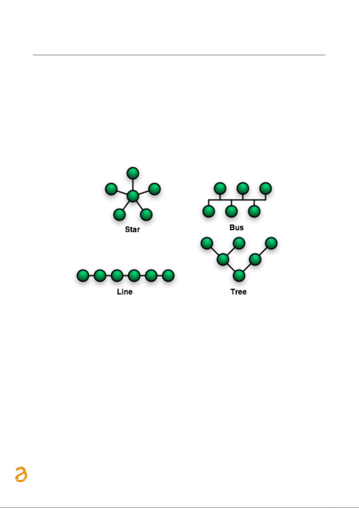
•Different types of bus topology: linear, star, and tree
Figure 1 - Bus topologies
1.2 Addressing
The M-Bus uses two types of addressing modes to detect the devices:
•Primary address: up to 250 primary addresses can be allocated within an M-Bus plant. The
primary address is normally allocated while setting up the central units.
•Secondary address: the secondary address consists of 8 bytes and allows the allocation of any
number. By default, the secondary address of the devices is the same as the manufacturer
serial number. This type of allocation prevents bus conflicts.

E Q U O B O X S I N . E Q L C 2 5 0 –U s e r G u i d e R e v . 1 . 0
S I N A P S I S . r . l. | V i a d e l l e Q u e r c e 1 1 / 1 3 - 0 6 0 8 3 B A S T I A U M B R A ( P G ) –I t a l y
T . + 3 9 075 8011604 - F . + 3 9 075 8014602| w w w . s i n a p s i t e c h . i t -i n f o @ s i n a p s i t e c h . i t 4
1.3 Sizing the M-Bus System
Cable type
•Shielded telephone cable 0.5mm²
•Cable maximum capacitive load: 152 nF/km
If you are using a cable with lower section, adapt the maximum length and the number of slaves
Follow the instructions provided in the table to size the M-Bus system
Type of plant
Maximum
distance
Overall cable
length
Cross-section
Number of
devices
(slaves)
Max.
transmission
rate
Small residential
buildings
350 m
1000 m
0.8 mm2
250
9600 Baud
Large residential
buildings
350 m
4000 m
0.8 mm2
250
2400 Baud
64
9600 Baud
Small complex
1000 m
4000 m
0.8 mm2
64
2400 Baud
Large
developments
…3000 m*
5000 m
1.5 mm2
64
2400 Baud
Direct vicinity
…5000 m*
7000 m
1.5 mm2
16
300 Baud
Point-to-point
connection
…10000 m*
10000 m
1.5 mm2
1
300 Baud
*Shielded cabling required at a distance in excess of 1000 m (see EN13757-2).
1.4 BUS signal specifications
M-Bus system
u.m.
Condition
Minimum
Typical
Maximum
Unit of
measure
ment
Number of devices per
segment
n
SIN.EQLC250
0
250
Transmission rate
T
300
2400
9600
Bd
Bus Voltage (Master)
UM
IM=0…400mA
30
39
42
V
Bus Voltage (slave)
US,R
30
42
V
Bus current (Master)
IM,V
SIN.EQLC250
0
375
mA
Current (slave)
IS,R
US=30…42V
0.75
1.2
1.5
mA
E Q U O B O X S I N . E Q L C 2 5 0 –U s e r G u i d e R e v . 1 . 0
S I N A P S I S . r . l. | V i a d e l l e Q u e r c e 1 1 / 1 3 - 0 6 0 8 3 B A S T I A U M B R A ( P G ) –I t a l y
T . + 3 9 075 8011604 - F . + 3 9 075 8014602| w w w . s i n a p s i t e c h . i t -i n f o @ s i n a p s i t e c h . i t 5
2. SIN.EQLC250 INSTALLATION
2.1 Description of the SIN.EQLC250
SIN.EQLC250 is a unit that reads M-Bus devices in compliance with the EN 13757-2 standard.
The level converter/repeater SIN.EQLC250 is the interface between M-Bus device and a read system.
It consists of a level converter and the associated power supply. In fact, the level converter and
associated power supply form a unit: no addition transformer or auxiliary power required.
The SIN.EQLC250 unit can be used in different ways:
•Connect up to 250 M-Bus devices (max. 250 simply M-Bus loads (*))
•Can be connected with the M-Bus web server of Equobox family (SIN.EQRTUEVO1T, SIN.EQRTU1,
SIN.EQRTU1T, SIN.EQRTU1X, SIN.EQRTU4), PXC devices, other M-Bus read / configuration systems
•Up to 6 level converters connected in parallel on an M-Bus network
•Up to 5 level converters as repeater (in series) on an M-Bus network
•Via RS-232 or RS-485 interfaces to read device data via the PXC device or a PC (level converter)
•Remote reading of M-Bus devices via M-Bus web server SIN.EQRTUEVO1T (Cloud).
*A unit M-Bus load is ≤1,5mA
NOTE: You can use the level converter at your own risk as an interface as well to suitable software and
devices by third-party manufacturers.
NOTE: The level converter is galvanically isolated. It protects against short circuits.
E Q U O B O X S I N . E Q L C 2 5 0 –U s e r G u i d e R e v . 1 . 0
S I N A P S I S . r . l. | V i a d e l l e Q u e r c e 1 1 / 1 3 - 0 6 0 8 3 B A S T I A U M B R A ( P G ) –I t a l y
T . + 3 9 075 8011604 - F . + 3 9 075 8014602| w w w . s i n a p s i t e c h . i t -i n f o @ s i n a p s i t e c h . i t 6
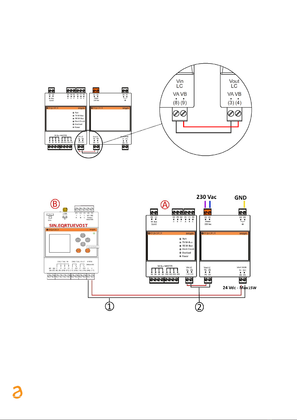
2.2 Operating modes of power supply
The power supply can be employed as follows:
•To power the level converter
1
Level converter / repeater
2
Power supply
•To power the M-Bus web server SIN.EQRTUxxx (*).In the example below there is the datalogger
SIN.EQRTUEVO1T.
A
Web server SIN.EQRTUxxx.
1
Connection web server SIN.EQRTUxxx with
auxiliary power supply (24Vdc) of SIN.EQLC250
B
Level converter/repeater SIN.EQLC250
2
Connection level converter/repeater with
power supply
* SIN.EQRTUxxx: SIN.EQRTU1, SIN.EQRTU4, SIN.EQRTU1T, SIN.EQRTU1X, SIN.EQRTUEVO1T

E Q U O B O X S I N . E Q L C 2 5 0 –U s e r G u i d e R e v . 1 . 0
S I N A P S I S . r . l. | V i a d e l l e Q u e r c e 1 1 / 1 3 - 0 6 0 8 3 B A S T I A U M B R A ( P G ) –I t a l y
T . + 3 9 075 8011604 - F . + 3 9 075 8014602| w w w . s i n a p s i t e c h . i t -i n f o @ s i n a p s i t e c h . i t 7
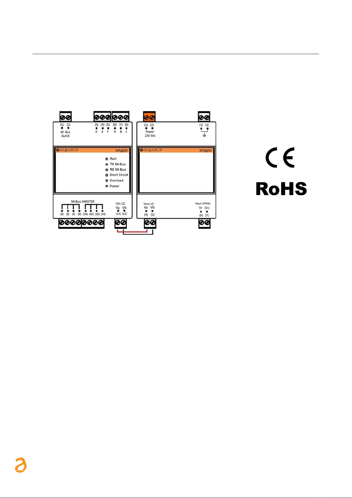
2.3 Connection terminals
SIN.EQLC250 looks like a device for mounting on DIN rail. The connectors/LEDs present are listed
below:
Figure 2 –Features and connectors Level Converter (SIN.EQLC250)
A
Main voltage AC 230 V
B
Power supply for level converter
(1) –Pin 1 for main power –230 Vac
(2) –Pin 2 for main power –230 Vac
(4) –power supply = (11) level converter
(5) –power supply = (12) level converter
C
Power out 24Vdc for web server (15W)
D
Electrical grounding
(6) - Pin V+ Output for datalogger
(7) - Pin V- Output for datalogger
(3) - Earth
E
Serial interface
F
Firmware update button
Serial interface RS232 and RS485 to connect
to a PC or M-Bus master.
Push button for reset and firmware update
RS-232:
A = TX
B = RX
C = GND
RS-485:
D = REF
E = D-
F = D+
G
M-Bus Slave
H
M-BUS Master interface
(1) –Pin 1 for M-Bus network to extend
(Repeater mode)
(2) –Pin 2 for M-Bus network to extend
(Repeater mode)
(9) –Pin 1 for connection M-Bus devices
(Master mode)
(10) –Pin 2 for connection M-Bus devices
(Master mode)
I
Status LED
Ref. Chap 2.6

E Q U O B O X S I N . E Q L C 2 5 0 –U s e r G u i d e R e v . 1 . 0
S I N A P S I S . r . l. | V i a d e l l e Q u e r c e 1 1 / 1 3 - 0 6 0 8 3 B A S T I A U M B R A ( P G ) –I t a l y
T . + 3 9 075 8011604 - F . + 3 9 075 8014602| w w w . s i n a p s i t e c h . i t -i n f o @ s i n a p s i t e c h . i t 8
2.4 Topology and connection of the M-Bus network
M-Bus technology allows good freedom of choice regarding network topology. It is possible to connect
the devices present in the plant according to a star, linear, tree topology or mixed as seen in 3 and 4.
However, ring topology (Figure 5 –Ring topology NOT ALLOWED) is not allowed. It is also not necessary
to observe any polarity of the bus, thus simplifying installation.
Figure 3 –Star Topology
Figure 4 –Mixed Topology
Figure 5 –Ring topology NOT ALLOWED
E Q U O B O X S I N . E Q L C 2 5 0 –U s e r G u i d e R e v . 1 . 0
S I N A P S I S . r . l. | V i a d e l l e Q u e r c e 1 1 / 1 3 - 0 6 0 8 3 B A S T I A U M B R A ( P G ) –I t a l y
T . + 3 9 075 8011604 - F . + 3 9 075 8014602| w w w . s i n a p s i t e c h . i t -i n f o @ s i n a p s i t e c h . i t 9
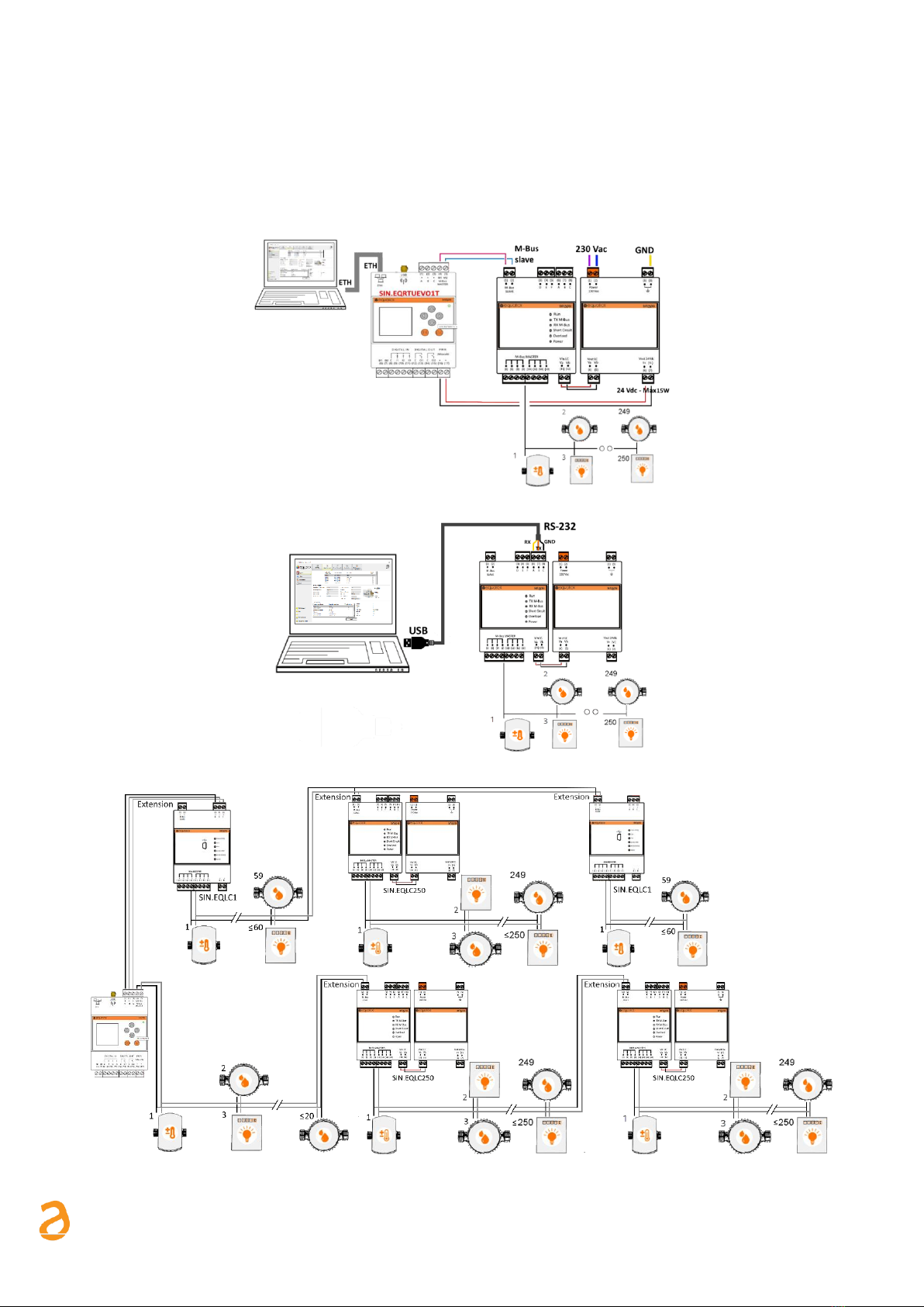
2.5 SIN.EQLC250 operation modes
SIN.EQLC250 can be used with M-Bus communication interface for SIN.EQRTUxxx datalogger (Figure 6)
or with a PC with EQUOBOX TOOLKIT software (SIN.EQSW1) (Figure 7) or as a repeater/extender of an
M-Bus network (Figure 8). The following figures show the connection diagrams for the different
operation modes.
Figure 6 –M-Bus communication interface for SIN.EQRTUxxx datalogger
Figure 7 –Connection a PC with EQUOBOX TOOLKIT software (SIN.EQSW1)
Figure 8 –Repeater/extender of an M-Bus network

E Q U O B O X S I N . E Q L C 2 5 0 –U s e r G u i d e R e v . 1 . 0
S I N A P S I S . r . l. | V i a d e l l e Q u e r c e 1 1 / 1 3 - 0 6 0 8 3 B A S T I A U M B R A ( P G ) –I t a l y
T . + 3 9 075 8011604 - F . + 3 9 075 8014602| w w w . s i n a p s i t e c h . i t -i n f o @ s i n a p s i t e c h . i t 10
2.6 Status LED
There are 6 LEDs present on the SIN.EQLC250 device, which indicate the operating status as shown in
the figure:
Figure 9 - Status indicators
Run
The (green) LED indicates the operational state of the device.
●Blinking at 1 Hz (slow) -> Device functions are being set up. No communication.
●Blinking at 10 Hz (fast) -> Device update pending.
●On -> The device is operational.
TX M-Bus
The (green) LED indicates the transmission state on the M-Bus network (terminals 9 and 10).
●On -> Data is transmitting.
●Off -> No data is transmitting.
RX M-Bus
The (orange) LED indicates the receive state of data on the M-Bus network (terminals 9 and 10).
●On -> Data is being received.
●Off -> No data is being received.
Short Circuit
The (red) LED indicates a short circuit on the bus, very high traffic, or a collision.
Overload
The (orange) LED indicates a bus overload that may prevent correct operation.
●On -> Bus overload that detected.
●Off -> No bus overload detected.
Power
The (green) LED indicates the state of the level converter power supply.
●On -> The device power supply is correct.
●Off -> Device power is not correct or unavailable.
2.7 Short circuit protection
During normal operation of the level converter, if a data collision occurs during communication with
the meters on the "M-Bus Master" bus, the "Short Circuit" LED may turn on.
In the case instead of a real c.c. (short circuit) in the absence of communication, the "M-Bus Master"
bus is disconnected (∆VM-Bus = 0) for a time equal to:
-5 seconds to the first short circuit detected.
-60 seconds per second consecutive short circuit detected.
-5 minutes to the third consecutive short circuit.
-24 hours from the fourth attempt onwards until the short circuit situation is resolved.
E Q U O B O X S I N . E Q L C 2 5 0 –U s e r G u i d e R e v . 1 . 0
S I N A P S I S . r . l. | V i a d e l l e Q u e r c e 1 1 / 1 3 - 0 6 0 8 3 B A S T I A U M B R A ( P G ) –I t a l y
T . + 3 9 075 8011604 - F . + 3 9 075 8014602| w w w . s i n a p s i t e c h . i t -i n f o @ s i n a p s i t e c h . i t 11
NOTE: If the conflict causing the short circuit signal is resolved during the power suspension on the "M-
Bus Master" bus, the level converter will continue to keep the bus de-energized until the expected reset
or until the device restarts or it feeds itself manually.
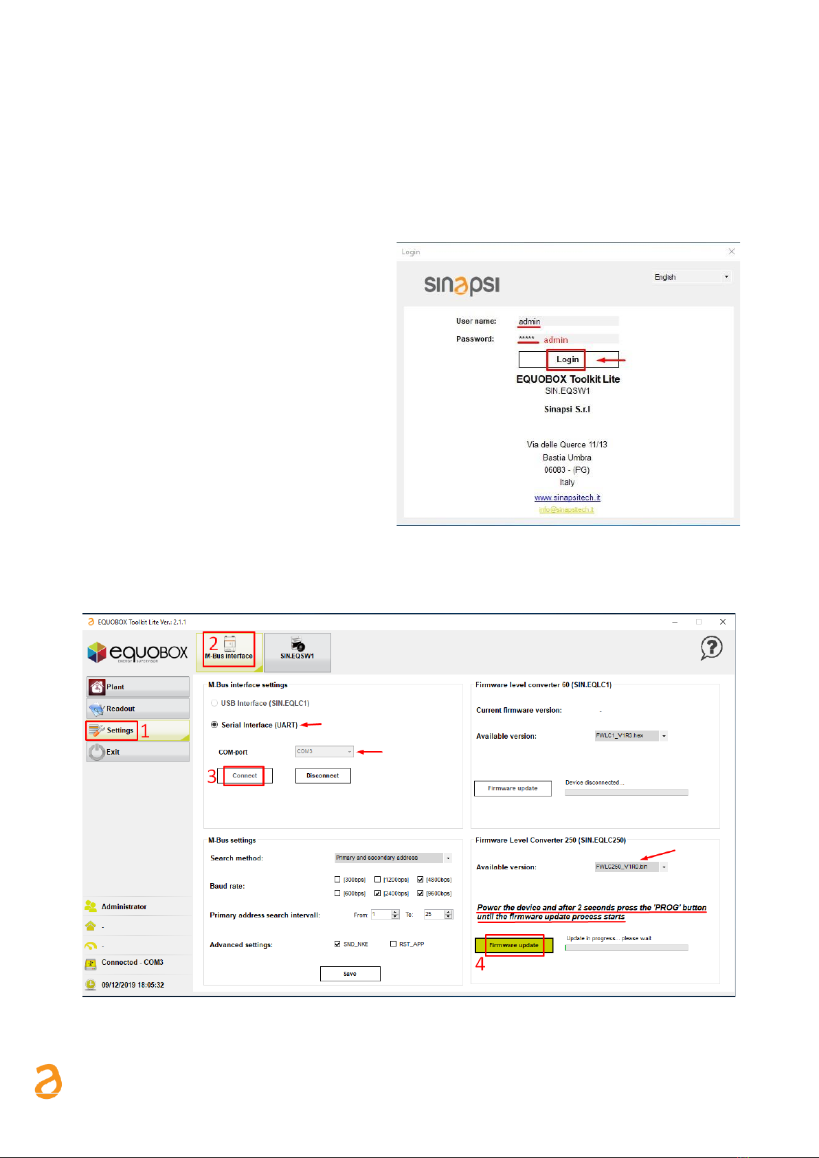
2.8 Firmware update
Through the EQUOBOX TOOLKIT Lite software (SIN.EQSW1) from version 2.0.15, it is possible to update
the version of firmware in SIN.EQLC250 if it is necessary (*).
•Enter the default credentials:
User: admin
Password: admin
•Select the Settings menu (1)
•Select the M-Bus interface tab (2)
•If unchecked, check the Serial Interface
(UART)
•Select the COM port where the device is
connected
•Connect to the device (3)
•In the Firmware Level Converter 250
(SIN.EQLC250) section:
oSelect the firmware version to be
installed.
oPress the button: Update Firmware (4)
oFollow the software step by step
instructions:
Figure 10 –Login to “Equobox Toolkit Lite”
- Disconnect the SIN.EQLC250 power supply without disconnecting the USB / RS232 cable.
- Power the device and after 2 seconds press and hold the 'PROG' button (F in fig. 2) until the
update process starts
Figure 11 –Firmware update of SIN.EQLC250
*It is not possible to check the firmware version currently installed in SIN.EQLC250

E Q U O B O X S I N . E Q L C 2 5 0 –U s e r G u i d e R e v . 1 . 0
S I N A P S I S . r . l. | V i a d e l l e Q u e r c e 1 1 / 1 3 - 0 6 0 8 3 B A S T I A U M B R A ( P G ) –I t a l y
T . + 3 9 075 8011604 - F . + 3 9 075 8014602| w w w . s i n a p s i t e c h . i t -i n f o @ s i n a p s i t e c h . i t 12
3. Troubleshooting
1) The device does not turn on (Power LED off)
- Check with multimeter that the supply voltage to the terminals (11) and (12) is 40 V.
2) LED Overload on:
- If the LED is on without any communication (RX and TX LEDs do not blink), there is an overload caused
by a possible short-circuits between the two poles of the bus or from an excessive number of
connected devices. Check the wiring.
3) The datalogger connected to the terminal does not detect some or all devices:
- Check the correct bus connection between the datalogger and terminal G of the SIN.EQLC250
- Check with the multimeter that the voltage on devices not recognized is between 32Vdc-42Vdc
- Verify that the communication settings of the M-Bus datalogger or the SW are compatible with the
devices (speed of communication, addressing)
4) The devices connected to the level converter in repeater mode do not communicate:
- Check the correct power supply
- Check the Run LED is on
- Check that the Short Circuit LED is off
- Check that the M-Bus network is connected to the G terminal of the SIN.EQLC250
- Check the correct voltage in terminals G and H of the repeater which must be between 32 Vdc - 42 Vdc

E Q U O B O X S I N . E Q L C 2 5 0 –U s e r G u i d e R e v . 1 . 0
S I N A P S I S . r . l. | V i a d e l l e Q u e r c e 1 1 / 1 3 - 0 6 0 8 3 B A S T I A U M B R A ( P G ) –I t a l y
T . + 3 9 075 8011604 - F . + 3 9 075 8014602| w w w . s i n a p s i t e c h . i t -i n f o @ s i n a p s i t e c h . i t 13
4. Technical features
POWER SUPPLY
Rated Voltage
AC 110...240 V
AC frequency
47...63 Hz
M-Bus Slave port absorption (in series)
≤ 3 mA (2 M-Bus Loads)
Rated Power
6W + 0.07 W for each connected M-Bus slave
Maximum consumption
45W, 45VA
Vout: DC 24 V, max. 15 VA
Internal fuse
PTC resistance and varistor
Fusing of supply lines
Circuit breaker:
Max 13 A, type B, C, D per EN 60898
or
Power supply with current limitation at 10 A
CONNECTIONS
M-Bus Slave (terminals 1 and 2):
Connections as a repeater / extender
M-Bus Master (terminals 9 and 10):
Connection to the M-Bus meters
Vout LC (terminals 4 and 5 on power supply) /
Vin LC (terminals 11 and 12 on level converter)
Power supply for level converter/repeater
40 Vdc
Vout 24 Vdc (terminals 6 and 7 on power supply)
DC 24 V, max 15 VA
INTERFACE
RS-232 (terminals A, B and C)
Connections as master to PC (using SIN.EQUSB232) or to data logger
Connect to a PC:
–Terminal A: RX (PC/data logger receiving line)
–Terminal B: TX (PC/data logger transmission line)
–Terminal C: GND (interface reference voltage)
Connection for the M-Bus web server SIN.EQ:
–Terminal 6[A] RS-232 with terminal 1[A] web server
–Terminal 7[B] RS-232 with terminal 2[B] web server
–Terminal 8[C] RS-232 with terminal 3[C] web server
RS-485 (terminals D, E and F)
Connection to connect to a PC or M-Bus devices
Connections to connect to PC/data logger as master:
–Terminal D: REF (interface reference voltage)
–Terminal E: D- (Receive/transmission line potential -)
–Terminal F: D+ (Receive/transmission line potential +)
M-BUS SECTION
Reference standard
EN13757-2 (Physical Layer)
Max. number of M-Bus devices (loads)
250 (≤1,5 mA)
Max. number of devices that can be connected
in cascade mode
6 level converters, of which 5 repeaters
Transmission speed (baud rate)
Minimum: 300bps
Typical: 2400bps
Maximum: 9600bps
M-Bus Master voltage
42V –32V
Bus current
Maximum 395 mA
Short circuit protection
Yes
Galvanic isolation
- RS-232 interface
- M-Bus interface

E Q U O B O X S I N . E Q L C 2 5 0 –U s e r G u i d e R e v . 1 . 0
S I N A P S I S . r . l. | V i a d e l l e Q u e r c e 1 1 / 1 3 - 0 6 0 8 3 B A S T I A U M B R A ( P G ) –I t a l y
T . + 3 9 075 8011604 - F . + 3 9 075 8014602| w w w . s i n a p s i t e c h . i t -i n f o @ s i n a p s i t e c h . i t 14
DIRECTIVES AND STANDARDS
Product standards
EN 62368-1 Information Technology Equipment Safety
Electromagnetic compatibility
For residential and industrial environments
EU conformity (CE)
MOD 07 AA Rev.0
ENVIRONMENTAL COMPATIBILITY
The product environmental declaration MOD 07 AA Rev.0 contains data on environmentally compatible product
design and assessments (RoHS compliance).
DEGREE OF PROTECTION
IP class
IP20 per EN60529
Protection class
II as per EN 62368-1
AMBIENT CONDITIONS
Storage
as per EN 60721-3-1:
Climatic conditions:
Temperature:
Air humidity:
Mechanical conditions:
Class 1K3
-25…+65 °C
5... 95% r.h.
Class 1M2
Transportation
as per EN 60721-3-3:
Climatic conditions:
Temperature:
Air humidity:
Mechanical conditions:
Class 2K3
-20…+65 °C
5... 95% r.h.
Class 2M2
Operation
as per EN 60721-3-3:
Climatic conditions:
Temperature:
Air humidity:
Mechanical conditions:
Class 3K5
-20…+55 °C
5... 95% r.h.
Class 3M2
MECHANICAL FEATURES
Dimensions (HxLxD)
110x71x62 mm (including terminals)
Installation type
35mm DIN rails (EN60715)
Materials and colours
Housing. PC + ASA, RAL 9010 (white)
Weight (level converter with mounting instructions)
0.392 kg for both devices
Packaging
0.055 kg
Table of contents
Popular Adapter manuals by other brands

Saramonic
Saramonic SmartRig II manual

Sony
Sony MSAC-US40 - MemoryStick Flash Memory Card USB 2.0... operating instructions

Panasonic
Panasonic KXTGA575 - 5 Instrucciones de operación

Adaptec
Adaptec 29320A installation guide

IOGear
IOGear GWAVR user manual

Swordfish
Swordfish VariPlug Dual USB operating instructions


