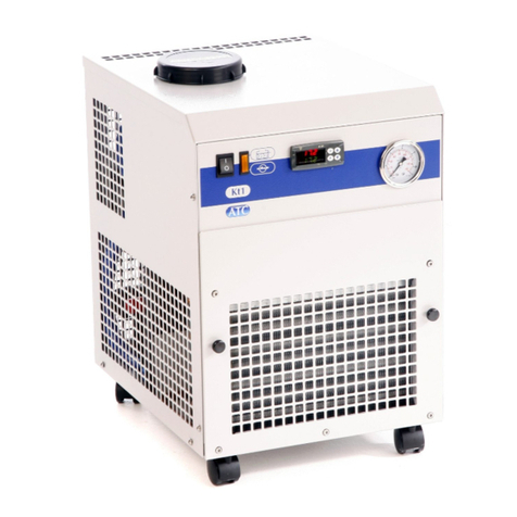
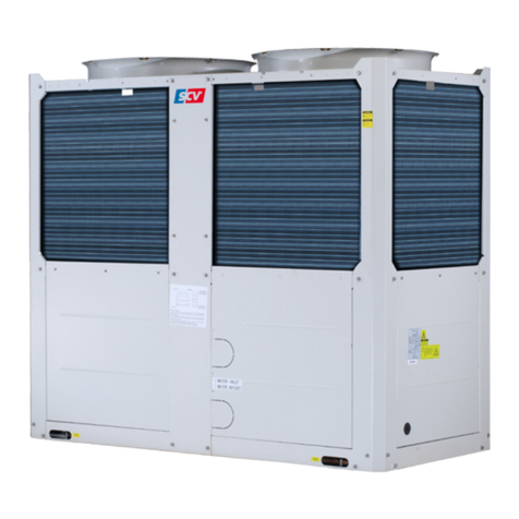
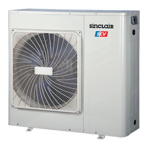
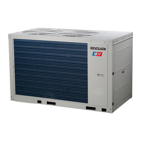
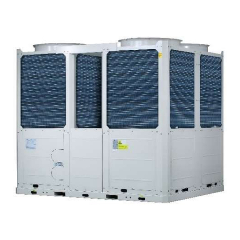
Sinclair SCV-EB Series User manual

AIR CONDITIONING
AIR-COOLED
MINI CHILLER UNIT
SERVICE MANUAL
SCV-XXXEB / EB-3


1
CONTENTS
Part 1 General Information............................................................................3
Part 2 Component Layout and Refrigerant Circuits .....................................5
Part 3 Control ...............................................................................................11
Part 4 Diagnosis and Troubleshooting......................................................... 23

2

4
1Product lineup
Model
Power supply(V/Ph/Hz)
Refrigerant
Appearance
SCV-50EB
220-240/1 /50
R32
SCV-70EB
220-240/1 /50
R32
SCV-100EB
220-240/1 /50
R32
SCV-120EB
220-240/1 /50
R32
SCV-140EB
220-240/1 /50
R32
SCV-160EB
220-240/1 /50
R32
SCV-120EB-3
380-415/3/50
R32
SCV-140EB-3
380-415/3/50
R32
SCV-160EB-3
380-415/3/50
R32
2Nomenclature
C
x
S
V
x
x
E
B
-
-
Power Supply
3: 3-phase, 380-415V, 50Hz
Refrigerant
B: R32
Unit category
E: Outdoor unit
Capacity index
The capacity in 0,1*kW
Variable
Chiller
Sinclair
3

6
1Layout of Functional Components
SCV-50EB / SCV-70EB / SCV-100EB
Safety valve
Plate heat exchanger
High pressure switch
Pump
Low pressure switch
Compressor
Electronic expansion valve
Water flow switch
Air purge valve
4-way valve
Pressure sensor
Expansion vessel

7
SCV-120EB / SCV-140EB / SCV-160EB
Safety valve
Plate heat exchanger
High pressure switch
Pump
Low pressure switch
Compressor
Electronic expansion valve
Water flow switch
Air purge valve
4-way valve
Pressure sensor
Expansion vessel

8
SCV-120EB-3 / SCV-140EB-3 / SCV-160EB-3
Safety valve
Plate heat exchanger
High pressure switch
Pump
Low pressure switch
Compressor
Electronic expansion valve
Water flow switch
Air purge valve
Pressure sensor
Expansion vessel
4-way valve

9
2Piping Diagrams
Refrigerant piping graphic example:
Heating and DHW mode
Cooling mode
High temperature, high pressure gas
High temperature, high pressure liquid
Low temperature, low pressure gas
Low temperature, low pressure gas liquid mixture
F
①
②
③
④
⑥
⑤
⑧
⑦
⑨⑩⑨
21 22
23 24 25
18
17
11
16
12
13
15
14
19
20
26
27
F
①
②
③
④
⑥
⑤
⑧
⑦
⑨⑩⑨
21 22
23 24 25
18
17
11
16
12
13
15
14
19
20
26
27

10
Legend
1
Compressor
15
Refrigerant gas pipe temperature sensor(T2B)
2
Discharge temperature sensor(Tp)
16
Pressure sensor
3
High pressure switch
17
Suction temperature sensor(Th)
4
4-way valve
18
Low pressure switch
5
Ambient temperature sensor(T4)
19
Water outlet temperature sensor(Tw_out)
6
Air side heat exchanger
20
Water inlet temperature sensor(Tw_in)
7
Fan
21
Expansion vessel
8
Air side heat exchanger temperature sensor(T3)
22
Pump
9
Strainer
23
Pressure relief valve
10
Capillary
24
Air purge valve
11
Electronic expansion valve
25
Water flow switch
12
Refrigerant liquid pipe temperature sensor(T2)
26
Water outlet
13
Accumulator cylinder
27
Water inlet
14
Plate heat exchanger
Key components:
1. Accumulator cylinder:
Stores liquid refrigerant and oil to protect compressor from liquid hammering.
2. Electronic expansion valve (EXV):
Controls refrigerant flow and reduces refrigerant pressure.
3. Four-way valve:
Controls refrigerant flow direction. Closed in cooling mode and open in heating mode. When closed, the air side heat
exchanger functions as a condenser and water side heat exchanger functions as an evaporator; when open, the air
side heat exchanger functions as an evaporator and water side heat exchanger function as a condenser.
4. High and low pressure switches:
Regulate refrigerant system pressure. When refrigerant system pressure rises above the upper limit or falls below the
lower limit, the high or low pressure switches turn off, stopping the compressor.
5. Air purge valve:
Automatically removes air from the water circuit.
6. Pressure relief valve:
Prevents excessive water pressure by opening at 43.5 psi (3 bar) and discharging water from the water circuit.
7. Expansion vessel:
Balances water system pressure. (Expansion vessel volume: 5L)
8. Water flow switch:
Detects water flow rate to protect compressor and water pump in the event of insufficient water flow.
9. Water pump:
Circulates water in the water circuit.

11
Part 3
Control
1 Stop operation......................................................................................... 12
2 Standby control ....................................................................................... 12
3 Startup control......................................................................................... 13
4 Normal operation control ........................................................................ 14
5 Protection control.................................................................................... 16
6 Special control ......................................................................................... 19

12
1Stop operation
The stop operation occurs for one of the following reasons:
1. Abnormal shutdown: in order to protect the compressors, if an abnormal state occurs the system makes a stop with
thermo off operation and an error code is displayed on the outdoor unit PCB digital displays and on the user interface.
2. The system stops when the set temperature has been reached.
2Standby control
2.1 Crankcase heater control
The crankcase heater is used to prevent refrigerant from mixing with compressor oil when the compressors are stopped.
The crankcase heater is controlled according to outdoor ambient temperature and the compressor on/off state. When the
outdoor ambient temperature is above 8°C or the compressor is running, the crankcase heater is off; when the outdoor
ambient temperature is at or below 8°C and either the compressor has been stopped for more than 3 hours or the unit has
just been powered-on (either manually or when the power has returned following a power outage), the crankcase heater
turns on.
2.2 Water pump control
When the outdoor unit is in standby, the internal and external circulator pumps run continuously.

13
3Startup control
3.1 Compressor sdtartup delay control
In initial startup control and in restart control (except in oil return operation and defrosting operation), compressor startup
is delayed such that a minimum of the set re-start delay time has elapsed since the compressor stopped, in order to
prevent frequent compressor on/off and to equalize the pressure within the refrigerant system. The compressor re-start
delays for cooling, heating modes are set on the user interface.
3.2 Compressor startup program
In initial startup control and in re-start control, compressor startup is controlled according to outdoor ambient
temperature. Compressor startup follows one of two startup programs until the target rotation speed is reached.
SCV-50EB / SCV-70EB / SCV-100EB
Ambient temperature is above 12°C for cooling mode
Ambient temperature is above 0°C for heating mode
Ambient temperature is below 12°C for cooling mode
Ambient temperature is below 0°C for heating mode
SCV-120EB / SCV-140EB / SCV-160EB
SCV-120EB-3 / SCV-140EB-3 / SCV-160EB-3
Ambient temperature is above 12°C for cooling mode
Ambient temperature is above 0°C for heating mode
Ambient temperature is below 12°C for cooling mode
Ambient temperature is below 0°C for heating mode
3.3 Startup control for heating operation
Component
Wiring diagram label
5~16kW
Control functions and states
Inverter compressor
COMP
●
Compressor startup program selected according to ambient temperature
DC fan motor
FAN
●
Fan runs at maximum speed
Electronic expansion valve
EXV
●
Position (steps) from 0 (fully closed) to 480 (fully open), controlled
according to outdoor ambient temperature, discharge temperature, suction
superheat, compressor speed and refrigerant system pressure
Four-way valve
4-WAY
●
On

14
3.4 Startup control for cooling operation
Component
Wiring diagram label
5~16kW
Control functions and states
Inverter compressor
COMP
●
Compressor startup program selected according to ambient temperature
DC fan motor
FAN
●
Fan run at maximum speed
Electronic expansion valve
EXV
●
Position (steps) from 0 (fully closed) to 480 (fully open), controlled
according to outdoor ambient temperature, discharge temperature, suction
superheat, compressor speed and refrigerant system pressure
Four-way valve
4-WAY
●
Off
4Normal operation control
4.1 Normal operation control for heating operation
Component
Wiring diagram label
5~16kW
Control functions and states
Inverter compressor
COMP
●
Controlled according to load requirement from temperature set and outlet
water temperature
DC fan motor
FAN
●
Controlled according to outdoor heat exchanger pipe temperature
Electronic expansion valve
EXV
●
Position (steps) from 0 (fully closed) to 480 (fully open), controlled
according to outdoor ambient temperature, discharge temperature, suction
superheat, compressor speed, refrigerant system pressure and temperature
Four-way valve
4-WAY
●
On
4.2 Normal operation control for cooling operation
Component
Wiring diagram label
5~16kW
Control functions and states
Inverter compressor
COMP
●
Controlled according to load requirement from temperature set and outlet
water temperature
DC fan motor
FAN
●
Controlled according to outdoor heat exchanger pipe temperature
Electronic expansion valve
EXV
●
Position (steps) from 0 (fully closed) to 480 (fully open), controlled
according to outdoor ambient temperature, discharge temperature, suction
superheat, compressor speed, refrigerant system pressure and temperature
Four-way valve
4-WAY
●
Off
4.3 Compressor output control
The compressor rotation speed is controlled according to the load requirement. Before compressor startup, heat pump
determines the compressor target speed according to outdoor ambient temperature, leaving water set temperature and
actual leaving water temperature and then runs the appropriate compressor startup program. Once the startup program is
complete, the compressor runs at the target rotation speed. During operation the compressor speed is controlled
according to the rate of change of water temperature, the refrigerant system pressure and temperature.
4.4 Compressor step control
The running speed of six-pole compressors in rotations per second (rps) is one third of the frequency (in Hz) of the
electrical input to the compressor motor. The frequency of the electrical input to the compressor motors can be altered at
a rate of 1Hz per second.
4.5 Four-way valve control
The four-way valve is used to change the direction of refrigerant flow through the water side heat exchanger in order to
switch between cooling and heating operations.

15
During heating operation, the four-way valve is on; during cooling and defrosting operations, the four-way valve is off.
4.6 Electronic expansion valve control
The position of the electronic expansion valve (EXV) is controlled in steps from 0 (fully closed) to 480 (fully open/standby
position).
At power-on:
The EXV first closes fully, then moves to the standby position.
After the compressor runs, the EXV is controlled according to suction superheat, discharge temperature,
pressure and compressor speed.
When the outdoor unit is in standby:
The EXV is at standby position.
When the outdoor unit stops:
The EXV first opens fully and remains for 30 seconds, then closes fully, then moves to the standby position.
4.7 Outdoor fan control
The speed of the outdoor unit fan is adjusted in steps, as shown below
Fan speed index
Fan speed (rpm)
5kW
7kW
9kW
12kW
14kW
16kW
W1
200
200
200
200
200
200
W2
250
250
250
250
250
250
W3
300
300
300
300
300
300
W4
350
350
350
350
350
350
W5
400
400
400
400
400
400
W6
450
450
450
450
450
450
W7
470
470
470
530
530
530
W8
530
530
530
600
600
600
W9
550
550
550
650
650
650
W10
/
590
590
730
730
730
W11
/
650
650
780
780
780
W12
/
/
/
/
820
820

16
5Protection control
5.1 High pressure protection control
This control protects the refrigerant system from abnormally high pressure and protects the compressor from transient
spikes in pressure.
Notes:
1. Pc: Discharge pressure
When the discharge pressure rises above 4.3MPa the system displays P1 protection and the unit stops running. When the
discharge pressure drops below 3.2MPa, the compressor enters re-start control.
5.2 Low pressure protection control
This control protects the refrigerant system from abnormally low pressure and protects the compressor from transient
drops in pressure.
Notes:
1. Pe: Suction pressure
When the suction pressure drops below 0.14MPa the system displays P0 protection and the unit stops running. When the
suction pressure rises above 0.3MPa, the compressor enters re-start control.
When P0 protection occurs 3 times in 60 minutes, the HP error is displayed. When an HP error occurs, a manual system
restart is required before the system can resume operation.
Pc> 4.3MPa
Pc< 3.2MPa
Normal operation
High pressure protection, error code P1 is displayed
Pe< 0.14MPa
Pe> 0.30MPa
Normal operation
Low pressure protection, error code P0 is displayed

17
5.3 Discharge temperature protection control
This control protects the compressor from abnormally high temperatures and transient spikes in temperature.
When the discharge temperature rises above 115°C the system displays P4 protection and the unit stops running. When
the discharge temperature drops below 95°C, the compressor enters re-start control.
Notes:
Tp: Discharge temperature
Th: Suction temperature
When the discharge temperature is lower than suction temperature for more than 12 minutes after compressor runs, the
system displays EA protection and heat pump stops running. After 3 minutes, the compressor enters re-start control
automatically.
If EA protection occurs 3 times within 2 hours, heat pump cannot be restarted unless it is powered on again.
5.4 Compressor current protection control
This control protects the compressor from abnormally high currents.
Current limitation for heat pump
Model name
SCV-50/70/100EB
SCV-120/140/160EB
SCV-120/140/160EB-3
Currentmax
18A
30A
14A
When the heat pump current rises above Currentmax the system displays P3 protection and the unit stops running. When
the heat pump current drops below Currentmax, the compressor enters re-start control.
Tp > 115°C
Tp < 95°C
Normal operation
High discharge temperature protection, error code P4 is displayed
Tp <Th for more than 12 minutes
After 3 minutes
Normal operation
Low discharge temperature protection, error code EA is displayed
Current > Currentmax
Current < Currentmax
Normal operation
Compressor current protection, error code P3 is displayed

18
5.5 Voltage protection control
This control protects the heat pump from abnormally high or abnormally low voltages.
When the phase voltage of AC power supply is at or above 265V, the system displays H7 protection and the unit stops
running. When the phase voltage drops below 265V for more than 30 seconds, the refrigerant system restarts once the
compressor re-start delay has elapsed.
When the phase voltage is at or below 172V, the system displays H7 protection and the unit stops running.
When the AC voltage rises to at or more than 180V, the refrigerant system restarts once the compressor re-start delay has
elapsed.
5.6 DC Fan motor protection control
This control protects the DC fan motors from strong winds and abnormal power supply. DC fan motor protection occurs
when any one of the following conditions are met:
Fan speed is less than 50rpm for more than 40s after fan operates.
Fan speed is lower than 50rpm for 3S,during normal operation
When DC fan motor protection control occurs the system displays the H6 error code and the unit stops running. After 3
seconds, the unit restarts automatically.
When H6 protection occurs 10 times in 120 minutes, the HH error is displayed. When an HH error occurs, a manual system
restart is required before the system can resume operation.
5.7 Water side heat exchanger anti-freeze protection control
This control protects the water side heat exchanger from ice formation.
The water side heat exchanger electric heater is controlled according to outdoor ambient temperature, water side heat
exchanger water inlet temperature and outlet temperature.
In cooling mode, if inlet water temperature or leaving water temperature or auxiliary heat source leaving water
temperature is below 4°C, heat pump stops and water pump keeps running for 30min. If water temperature is still below
4°C, heat pump turns to heating mode. the anti-freeze protection actions.
In heating standby mode, if ambient temperature is below 3°C and inlet water temperature or leaving water temperature
or auxiliary heat source leaving water temperature is below 5°C, heat pump stops and water pump keeps running for
30min. If ambient temperature is still below 3°C and water temperature is still below 5°C, heat pump turns to heating
mode. the anti-freeze protection actions; if leaving water temperature is below 2°C, the anti-freeze protection actions.
In heating standby mode, if leaving water temperature is below 2°C, heat pump stops and water pump keeps running for
30min. If water temperature is still below 2°C heat pump turns to heating mode to protect from anti-freezing.
When water side heat exchanger anti-freeze protection occurs the system displays error code Pb and the unit stops
running.
Voltage ≥265V or Voltage ≤172V
180V < Voltage < 256V for 30s
Normal operation
Compressor voltage protection, error code H7 is displayed
This manual suits for next models
10
Table of contents
Other Sinclair Chiller manuals
Popular Chiller manuals by other brands

McQuay
McQuay MCW200 Technical manual

Daikin
Daikin EWYD-4ZB Installation, operation and maintenance manual

JBJ Lighting
JBJ Lighting mini ARCTICA DBI-050 owner's manual

Quantech
Quantech QTH1 0035 quick start guide

Trane
Trane RTHD Troubleshooting

Modine Manufacturing
Modine Manufacturing Airedale TurboChill R1234ze manual