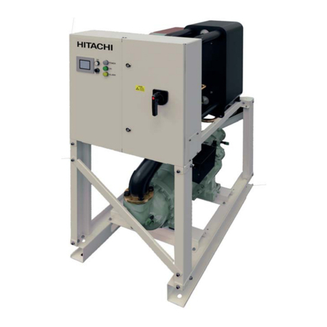
Hitachi SAMURAI Series User manual

Installation, operation and
maintenance instructions.
Design information.
RCUE40CLG2
RCUE50CLG2
RCUE60CLG2
RCUE80CLG2
RCUE100CLG2
RCUE120CLG2
Technical Catalogue
SAMURAI SERIES
CONDENSERLESS WATER CHILLERS
-SCREW TYPE-
CLG2


Specications in this manual are subject to change without notice in order that
HITACHI may bring the latest innovations to their customers.
Whilst every effort is made to ensure that all specications are correct, printing errors
are beyond Hitachi’s control; Hitachi cannot be held responsible for these errors.


Contents
TCGB0051 rev.0 - 09/2009
5
Contents
Important Notice
Features and Benets
Operation Instructions
Components of chiller
Preparation Initial Check
Installation
Test Running
Controller Adjustment
Self-Inspection Functions
Control System
Maintenance
Troubleshooting
General Specications
Drawings
Model Selection
Application Data
Components Data
1
2
3
4
5
6
7
8
9
10
11
12
13
14
15
16
17


7
Contents
TCGB0051 rev 0 - 09/2009
Technical Catalogue
Contents
1. Important notice ................................................................................................................11
2. Features and benets .......................................................................................................13
2.1. Chiller picture ........................................................................................................................................... 14
2.2. Compressor ............................................................................................................................................. 14
2.3. Control ..................................................................................................................................................... 16
2.4. Heat Exchanger ....................................................................................................................................... 17
2.5. Electronic Expansion Valve ..................................................................................................................... 18
3. Operation instructions.......................................................................................................19
3.1. HITACHI condenserless Water Chiller Models: RCUE(40~120)CLG2 .................................................... 20
4. Components of chiller .......................................................................................................21
4.1. Structure drawing .................................................................................................................................... 22
5. Preparation initial check ...................................................................................................23
5.1. Initial check .............................................................................................................................................. 24
5.2. Placing the unit ........................................................................................................................................ 25
5.3. Centre of gravity ...................................................................................................................................... 26
5.4. Service space and foundation ................................................................................................................. 27
5.5. Transportation by rigging ......................................................................................................................... 28
6. Installation ........................................................................................................................29
6.1. Electrical Wiring ....................................................................................................................................... 30
6.2. Water Piping ............................................................................................................................................ 32
6.3. Minimum internal system water volume .................................................................................................. 33
6.4. Water control ........................................................................................................................................... 34
6.5. Refrigerant piping .................................................................................................................................... 34
6.6. BMS connection ...................................................................................................................................... 37
6.7.CSC-5S .................................................................................................................................................... 44
6.8. Installation nal check ............................................................................................................................ 45
7. Test running ......................................................................................................................47
7.1. Preparation .............................................................................................................................................. 48
7.2. Test running procedure ............................................................................................................................ 48
7.3. Instructions after test running .................................................................................................................. 48
8. Controller adjustment .......................................................................................................49
8.1. PCB Drawing ........................................................................................................................................... 50
8.2. Control System ........................................................................................................................................ 51
8.3. Controller Adjustment .............................................................................................................................. 51
9. Self-Inspection functions ..................................................................................................55
9.1. Alarm Indication ....................................................................................................................................... 56
9.2. Normal Indication ..................................................................................................................................... 57
9.3. Function for indication of operation condition .......................................................................................... 57

TCGB0051 rev 0 - 09/2009
8
Contents
Technical Catalogue
Contents (Cont.)
10. Control system................................................................................................................63
10.1. Standard operating sequence for RCUE40CLG2, RCUE50CLG2 and RCUE60CLG2 ....................... 64
10.2. Standard operating sequence for RCUE80CLG2, RCUE100CLG2 and RCUE120CLG2 ................... 65
11. Maintenance ...................................................................................................................67
11.1. Components........................................................................................................................................... 68
11.2. Lubrication ............................................................................................................................................. 68
11.3. Deposits ................................................................................................................................................. 68
11.4. Cleaning method .................................................................................................................................... 69
11.5. Winter shutdown .................................................................................................................................... 70
11.6. Spring start-up ....................................................................................................................................... 70
11.7. Part replacement.................................................................................................................................... 71
11.8. Refrigeration cycle ................................................................................................................................. 71
11.9. Refrigerant cycle diagram of Hitachi condenserless Chiller
(RCUE(40,50,60,80,100,120)CLG2 .................................................................................................... 72
11.10. Compressor removal............................................................................................................................ 73
11.11. Safety and protection control ............................................................................................................... 73
11.12. Normal operating pressure .................................................................................................................. 75
11.13. Test running and maintenance record .................................................................................................. 76
11.14. Daily operating records ........................................................................................................................ 77
11.15. Servicing for R407C refrigerant system ............................................................................................... 78
12. Troubleshooting ..............................................................................................................79
12.1. Troubleshooting table ............................................................................................................................ 80
13. General specications ....................................................................................................83
13.1. General data .......................................................................................................................................... 84
13.2. Option line up ........................................................................................................................................ 86
14. Drawings.........................................................................................................................87
14.1. Dimensional Drawings ........................................................................................................................... 88
14.2. Wiring Diagrams .................................................................................................................................... 91
15. Model selection...............................................................................................................99
15.1. Selection Example ............................................................................................................................... 100
15.2. Performance Table............................................................................................................................... 101
15.3. Electrical Data ..................................................................................................................................... 105
15.4. Sound Data .......................................................................................................................................... 106
16. Application Data............................................................................................................107
16.1. Working Range .................................................................................................................................... 108
16.2. Part Load Performance ....................................................................................................................... 108
16.3. Ethylene Glycol Application ..................................................................................................................110
17. Components data ......................................................................................................... 113
17.1. Compressor ..........................................................................................................................................114
17.2. Water Cooler .........................................................................................................................................114

9
Contents
TCGB0051 rev 0 - 09/2009
Technical Catalogue
¡Unit code list
NOTE:
MODEL CODIFICATION Please check by model name your condenserless type, its abbreviation and
reference number in this technical catalogue.
CLG2 SERIES
Unit Code Unit Code
RCUE40CLG2 8E042072 RCUE80CLG2 8E082072
RCUE50CLG2 8E052072 RCUE100CLG2 8E102072
RCUE60CLG2 8E062072 RCUE120CLG2 8E122072
3~
RCUE60CLG2
Unit type
Capacity
(HP)
Series
R407C
refrigerant
Condenserless


Important Notice
Technical Catalogue
1
1.
Important notice
11
TCGB0051 rev 0 - 09/2009
HITACHI pursues a policy of continuing improvement in design and performance of Products. The right is therefore
reserved to vary specications without notice.
HITACHI cannot anticipate every possible circumstance that might involve a potential hazard.
No part of this manual may be reproduced without written permission.
Signal words (DANGER, WARNING and CAUTION) are used to identify levels of hazard seriousness. Denitions for
identifying hazard levels are provided below with their respective signal words.
DANGER:
Immediate hazards which WILL result in severe personal injury or death.
WARNING:
Hazards or unsafe practices which COULD result in severe personal injury or death.
CAUTION:
Hazards or unsafe practices which COULD result in minor personal injury or product or property damage.
NOTE:
Useful information for operation and/or maintenance.
If you have any questions, contact your contractor or dealer of HITACHI.
This instruction gives a common description and information for this condenser less water Chiller which you operate as
well as for other models.
This condenser less water Chiller has been designed for the following temperatures. Operate the condenser less water
Chiller within this range.
°C
Working Range Maximum Minimum
Condensing
Temperature 65 30
Chilled Water
15 5
Outlet Temperature
These instructions should be considered as a permanent part of the condenser less water Chiller equipment and should
remain with the condenser less water Chiller equipment.


Features and Benefits
Technical Catalogue
2
2.
Features and Benefits
13
TCGB0051 rev 0 - 09/2009
Contents
2. Features and benets ..............................................................................13
2.1. Chiller picture...................................................................................................................14
2.2. Compressor .....................................................................................................................14
2.3. Control .............................................................................................................................16
2.4. Heat Exchanger ...............................................................................................................17
2.5. Electronic Expansion Valve .............................................................................................18

Features and Benefits
Technical Catalogue
TCGB0051 rev 0 - 09/2009
14
2.1. Chiller picture
HITACHI is a world leader in technology and with continual research and product development, now offers a screw type
Condenser less Chillers.
A range of capacity are available from 120 kW to 360 kW.
2.2. Compressor
¡THE SAMURAI RANGE INCORPORATES THE LATEST DEVELOPMENT OF HITACHI´S SCREW COMPRESSOR
TECHNOLOGY FOR THE NEW MILLENNIUM.
Highly Reliable HITACHI Two-Pole
Motor
Built-in Oil Separator (Cyclone oil
separator)
Oil Sight Glass
Oil Heater
High precision Twin Screw Rotors
Suction Filter

Features and Benefits
Technical Catalogue
2
15
TCGB0051 rev 0 - 09/2009
¡TWIN SCREW COMPRESSOR
By having so few moving parts, it has become highly reliable with very low noise level and low vibration
LOW VIBRATION
Reciprocating Screw
AMPLITUDE (µm)
Time (second)
¡PRINCIPLE OF COMPRESSION
¡CONTINUOUS CAPACITY CONTROL
HITACHI´s Continuous Capacity Control system uses advanced electronic controls to position the innitely variable
slide valve within each compressor.
This modulation allows exact load control and accurate chilled water temperature without the need for expensive
inverters.
COOLING LOAD %
Cooling load = continuos capacity control
Step
control
TIME (Hour)
Suction Port
Discharge Port

Features and Benefits
Technical Catalogue
TCGB0051 rev 0 - 09/2009
16
¡Energy Saving
Thanks to Continuous Capacity Control, 15~20% energy saving is possible compared with current step control
systems due to the following:
−The cooling load can be more closely matched
−Continuous Capacity Control takes advantage of high efciency part load performance.
−Frequent compressor starts and stops are eliminated.
PART LOAD PERFORMANCE
2.3. Control
¡Many Functions
Newly developed Control Board has many functions shown below as standard.
−Forced compressor load control
−2 different temperature setting
−Memory for data in alarm
−Automatic restart after power failure
MOTOR INPUT (%)
Continuous
Capacity
Control
COOLING CAPACITY (%)

Features and Benefits
Technical Catalogue
2
17
TCGB0051 rev 0 - 09/2009
¡Precise Temperature Control
Combination of “Continuous Capacity Control Compressor” and “HITACHI´s unique electronic controls” enable the
Chiller to control outlet water temperature precisely, independent of cooling load.
This control benets not only air-conditioning but also industrial process use.
CONTINUOUS CAPACITY CONTROL
TIME
Load Down
Neutral =2ºC Standard
(Minimum 0.5ºC)
Load Up 2
Load Up 1
(Quick cooling)
Outlet Water
Temperature
WATER TEMPERATURE
Start
CONVENTIONAL STEP CONTROL
WATER TEMPERATURE
Restart
OutletTemperature
1st step
Final step
Temperature
Band 7ºC
(normally)
2.4. Heat Exchanger
¡Plate Type Heat Exchanger
The new Condenser less Chillers are equipped with plate type Heat Exchangers, which have many advantages
when compared with conventional Shell & Tube heat exchanger as described below:
- Less Refrigerant (Small Internal Volume)
- Clean (Stainless Steel)
- High efciency (closer approach temperature)
- Plate type heat exchanger can provide improved
cooling capacity for R407C
CAPACITY (%)
SHELL & TUBE PLATE

Features and Benefits
Technical Catalogue
TCGB0051 rev 0 - 09/2009
18
2.5. Electronic Expansion Valve
This unit are equipped with an electronic expansion valve to provide sophisticated control under any temperature
condition.
The electronic expansion valve provides reduced electrical power consumption compared to the classical system.

Operation Instructions
Technical Catalogue
3
3.
Operation Instructions
19
TCGB0051 rev 0 - 09/2009
Contents
3. Operation instructions..............................................................................19
3.1. HITACHI condenserless Water Chiller Models: RCUE(40~120)CLG2 ............................20

Operation Instructions
Technical Catalogue
TCGB0051 rev 0 - 09/2009
20
3.1. HITACHI condenserless Water Chiller Models: RCUE(40~120)CLG2
¡To Start the Unit.
1. Open the water inlet and outlet valves.
2. After assuring that all control switches have been cut OFF, and the “LOCAL/REMOTE” switch on the
printed circuit board is in the “LOCAL” position, turn ON the power switch.
3. Conrm that phases R, S and T are correctly connected. The correct phase connection can be
checked by a phase sequence indicator. If not correctly connected, the compressor does not start due
to activation of a reversal phase protection device. Cut the main switch and interchange two of three
terminals, R, S and T at the main power source terminals.
4. Fully open the discharge and liquid line stop valves.
5. Operate the chilled water pump.
6. Set the Dip SW at the desired temperature
7. Depress the “ON” push button of the operation Switch
¡To Stop the Unit
1. Depress the “*OFF” push button switch.
( * Field –Supplied)
2. Switch OFF the main power source when the unit is shut down for a long period of time.
¡Pilot Lamp
The red LED indicates the normal operation.
When the orange LED is activated, any one of the safety devices may be functioning.
Please contact your service shop, if this condition is detected.
¡Daily Checking
1. Check the power supply to ensure that it is proper.
2. Check for abnormal sounds and vibrations.
3. Check the unit amperage.
4. Check the operating pressure.
¡Troubleshooting
−Unit Does Not Start
1. Is the main switch ON?
2. Is the main fuse OK?
3. Is the chilled water running?
4. Are the thermostats calling for the cooling operation?
¡Poor Cooling Operation
1. Is there sufcient Air supplied to the condenser?
2. Is the setting temperature correct?
3. Are the operating pressures normal?
4. Is there sufcient water running through the water cooler?
¡Maintenance
1. Remove any obstacles to condenser Airow, and clean the condenser.
2. Clean the unit with a cleaner.
3. Clean the water cooler. (It is recommended that a specialist will be contacted for this type of work.)
DANGER:
Switch OFF main interruptor (M.I) for any work inside Electrical Box.
Other manuals for SAMURAI Series
3
This manual suits for next models
1
Table of contents
Other Hitachi Chiller manuals
Popular Chiller manuals by other brands

CLIVET
CLIVET WiSAN-YSE1 10.1 Service manual

Multistack
Multistack Airstack ASPX Series Operation and maintenance manual

McQuay
McQuay AWS operating manual

Trane
Trane CenTraVac Installation - general information

Samsung
Samsung DVM Chiller Training

Daikin
Daikin EWAD TB Installation, operation and maintenance manual