sinercom SCS2ENMD48.3x30 User manual

Power Supplies
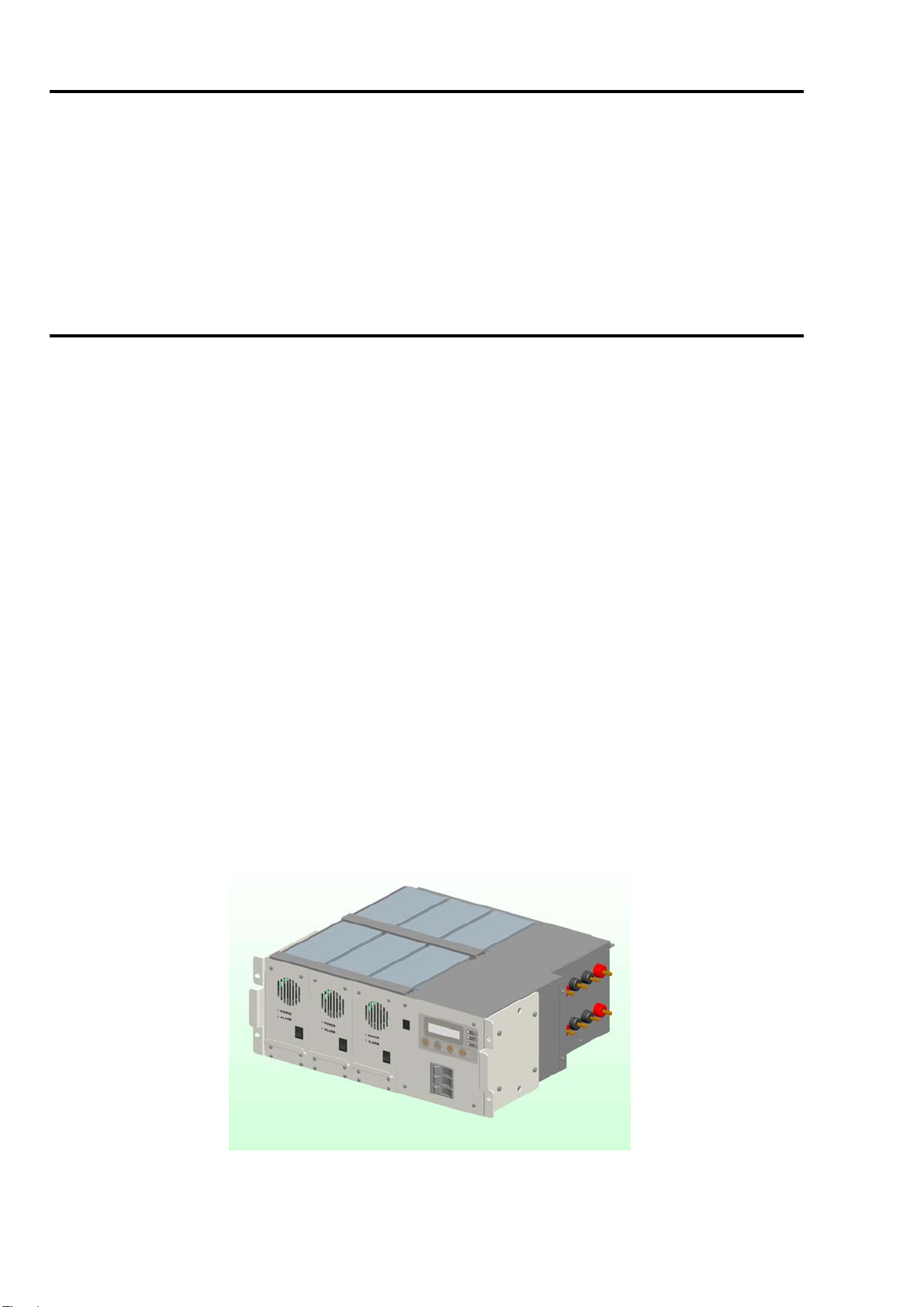
SCS2ENMD48.3x30
Modular Version
Input 230 Vac
Output 48 Vdc
90 A
Sinercom S.r.l.
Headquarter: Via G. Cappalonga 9/A- 00043 Ciampino (RM) - Italy
tel. +39.06.79800323 fax +39.06.79814644
Factory: Via Cascina Secchi 247/4b - 24040 Isso (BG) - Italy
tel. +39.0363.938231 fax +39.0363.998235
USERMANUAL

TABLE OF CONTENTS
1.0 WARNINGS AND SAFETY REGULATIONS ………………………………………………….… 3
1.1 DECLARATION OF COMFORMITY ……………………………………………………. 3
1.2 IMPORTANT SAFETY ISTRUCTION ………………………………………………………. 3
1.3 IDENTIFICATION OF DANGERS AND MEASURES FOR PREVENTION ………………. 4
1.3.1 Electricity Risks ……………………………………………………………….. 4
1.3.2 Fire Risks …………………………………………………………………….. 4
1.3.3 Mechanical Risks …………………………………………………………… 4
2.0 INTRODUCTION …………………………………………………………………………………………. 4
2.1 AN OVERALL VIEW ……………………………………………………………………………… 5
3.0 STRUCTURE ……………………………………………………………………………………………… 5
3.1 MECHANICAL STRUCTURE …………………………………………………….. 6
3.2 FRONT PANEL ……………………………………………………………………. 6
3.3 REAR PANEL …………………………………………………………………….. 6
4.0 TECHNICAL FEATURES ………………………………………………………………………. 6
4.1 TECHNICAL INFORMATION …………………………………………………………………… 6
4.2 FUSES ………………………………………………………………………………………….. 7
4.3 BATTERIES ………………………………………………………………………………………… 7
4.4 ELEMENTS OF PROTECTION ……………………………………………………………… 7
5.0 INSTALLATION ………………………………………………………………………………………... 7
5.1 PACKING CASE …………………………………………………………………………………… 7
5.2 PRELIMINARY CONTROLS …………………………………………………………………….. 7
5.3 INSTALLATION ………………………………………………………………………………….. 8
5.4 SWITCHING ON …………………………………………………………………………………… 9
5.5 SWITCHING OFF …………………………………………………………………………………. 9
6.0 FUNCTIONING ……………………………………………………………………………………… 10
6.1 OPERATIVE ELEMENTS ……………………………………………………………………… 10
6.2 ACOUSTIC SIGNALS …………………………………………………………………… 10
6.3 LED INDICATORS …………………………………………………………… 10
6.4 TELE-ALARM SIGNALS ……………………………………………………….. 11
6.5 DISPLAY FOR LOCAL DIAGNOSTIC ……………………………………………. 11
6.5.1 Battery Test …………………………………………………………………………….. 12
6.5.2 Alarm Message …………………………………………………………………… 13
6.6 FUNCTIONAL PARAMETER PROGRAMMING ………………………………………. 13
6.6.1 Past Messages …………………………………………………………………………. 13
6.6.2 Date And Time Setting ……………………………………………………………….. 13
6.6.3 Assistance ………………………………………………………………………………… 14
F1 FIGURA 1 OVERALL VIEW ………………………………………………………………………. 5
F2 FIGURA 2 OPERATIVE ELEMENTS ………….…………………………………………………… 10
F3 FIGURA 3 TELE-ALARM CONTACTS ……………………………………………………… 11
T1 TABELLA 1 TECHNICAL INFORMATION …………………………………………………………… 6
T2 TABELLA 2 FUSE INFORMATION ………………………………….………………………….. 7
T3 TABELLA 3 BATTERY INFORMATION ……………………………………………………………. 7
T4 TABELLA 4 LED SIGNALS …………………………………………………………………. 10
T5 TABELLA 5 FREE CONTACTS FOR TELE-ALARMS …………………………………………….. 11
T6 TABELLA 6 UNIT DISPLAY CONSOLE ………………………………………………………….. 12
T7 TABELLA 7 UNIT DISPLAY MESSAGES ………………………………………………………….. 12
T8 TABELLA 8 ALARM MESSAGES ……………………………………………………………… 13
T9 TABELLA 9 MESSAGES AND FUNCTIONING ASSISTANCE ………………………………… 14

3
1.0 SAFETY REGULATIONS
1.1 DECLARATION OF COMFORMITY
This device has been produced in such a way as to guarantee a safe functioning provided that it is utilized for the
purposes it was made for and that the regulations, instructions for use and installation provided by the manufacturer are
followed. The device has a CE stamp and it has been produced on the basis of what is defined:
EU Directives 2004/108/CE, relating to electromagnetic compatibility. ( amending directive 89/336/EEC);
EU Directives 2006/95/CE on equipment designed for use within certain voltage limits.
1.3 IDENTIFICATION OF DANGERS AND MEASURES FOR PREVENTION
1.3.1 ELECTRICITY RISKS ( electrical risk )
This device is produced according to the 2006/95/CE directive and is conform to the EN 60950 rule which regulates the
safety of electrical and electronic products.
In the case of circuit parts which are subject to dangerous tensions, they are identified by specific labels, as indicated in
the EN 60950 normative.
Any intervention on these circuits carried out by non-expert technicians is dangerous.
1.3.2 FIRE RISKS
The parts which make up the device do not have a specific point of applicable or definite flammability. The basic products
used for their construction are usually classified UL 94 V-O. During the normal conditions of movement, storage,
handling and utilization there is no danger of self-combustion. However, in case of a fire , good ventilation must be
guaranteed along with the use of oxygen masks.
Do not use water to put out the fire.
1.3.3 MECHANICAL RISKS
The assembly and operation of this device must be carried out according to the instructions presented in this manual.
THE MANUFACTURER DECLINES ALL RESPONSIBILTY IF ANY OF THE REGULATIONS AND SAFETY
MEASURES ARE NOT OBSERVED AND IF THE DEVICE IS NOT PROPERLY USED.
4
2.0 INTRODUCTION
SCS2ENMD48 is an apparatus suitable for food systems in DC-48VDC Universal Input, typically used in the field of
telecommunication (e.g. telephone communication station). SCS2ENMD48 It can be configured by two to three rectifiers
model ENR44830AL with hot swappable function. It’s guarantees supply continuity even in the case of an electrical black
out, thanks to the batteries connected to the system.
The main technical features of this power supplies are sinusoidal absorption with a power factor over 99%, high
efficiency and a output voltage stable with low psophometric noise, comprehensive monitoring function to both the
battery management, load and many backup monitoring signals, Ethernet terminals has been provided and one group of
totally 4 relay contact warning terminal for the remote controlling. A synoptic panel shows all the energy station working
parameter into the display. This unit includes a microprocessor controller that manages the display, the unit parameters,
the alarms, the serial and LAN interface. Besides the microprocessor takes care of the battery life disconnecting the
battery when its voltage is too low. When an alarm or failure is present, It will send the alarm message by LAN interface
and, in the same time, enable the corresponding alarm contact.
3.0 STRUCTURE
SCS2ENMD48 station is assembled in a rack structure including until three rectifiers. On the bottom are positioned the
batteries. Between the sub rack and the battery are the terminals and switches necessary to the system.
3.1
General description
In the sub-rack are accessible the inputs and outputs that users need to connect to the loads and AC main power. The
electronic part of the energy station is totally protected by metallic box. The use of hot-swappable power supply,
facilitates the system maintenance operations, hence the assistance of the energy station may be made directly on site.
Rectifier uses forced cooling to dissipate the heat produced by the electronic power components.
The SCS2ENMD48 is engineered using advanced technology. A high frequency push-pull converter topology is used in this model.
Power is transferred to the load via a transformer, therefore output voltage returns are DC-isolated from input AC returns. An
inductor and capacitor filters the PWM signal on the secondary transformer so as to minimize the output voltage ripple and the
psophometric noise. The main advantage of this method is greater efficiency with a smaller size and lower heat generation. The
power supply module includes an input Power Factor Conversion circuit. This circuit controls the input current so that the generated
current is proportional to the mains voltage waveform (a sine wave) in order to obtain a power factor as close as possible to unity.
The PFC circuit attempts to maintain a constant DC bus voltage on its output while drawing a current that is always in phase with
input frequency. These DC bus voltage drive the push-pull section.
This power supply share the load with an analog circuit while a microprocessor controls several important points of the supply, the
output current and others. These information are transferred to the synoptic panel by a can-bus interface.
The SYNOPTIC PANEL is the heart of the system. A display and a maintenance console visualize and control the fundamental
parameters of operations and points out any state of alarm which may arise.
These indications are signaled in real time and are recorded within an “historical” menu. Thanks to the information provided, the
user is able to completely control the system, preventing any critical situations and correcting any eventual malfunctioning of the
system.
The SCS2ENMD48 station can be equipped with a LAN interface optional that allows control all parameters of the system and
manages the Tele-diagnosis service. The LAN network uses the SNMP protocol to control the station on the local and remote
network (WAN).
3.2 View

5
4.0 TECHNICAL INFORMATION
SCS2ENMD48 technical information :
POWER SYSTEM CHARACTERISTICS SCS2MD48.3X30
System configuration Monofase - 3 module
INPUT
Rated input voltage range 230Vac +15% -20% (1F+N)
Input voltage range 175 – 276Vac
Input voltage frequency 47-63Hz (typical 50/60)
Nominal input current 23 A
Max input current 27 A
OUTPUT
Output voltage range 43-58Vdc ( Typical 54,4)
Max Output power 90A
Combined regulation ≤± 1%
Output ripple and noise ≤200mVp-p
Current sharing imbalance ≤±5% (Load range:50-100%)
Voltage Static regulation ±1% ( Load 10% - 100%)
Efficiency ≥90%
Psophometrically with battery connected <2mV (-51.7dBm)
Voltage ripple with battery connected <100mVeff.
Output low-voltage battery protection 43 Vcc ±2%
Other Protection Over-Temperature, Overload,
DISPLAY AND SIGNALINGS
Signal LED Plant powered, Battery mode, Alarm
Views Display LCD (16 x 2 Line) Output voltage – Input AC voltage – Load current – Battery charging Current –
Battery test – Date/Time – Historical menù – Setup – Service
Dry contacts alarm ( NO or NC ) Plant powered – Battery mode – Battery low – Alarms
OTHER REQUIREMENT
Acoustic Noise No higher than 55dB (A)
Cooling Forced air cooling
Dimension L x W x H mm 437 x 430 x 176
Weight 24Kg
Operating temperature 0°C to +45°C
Storage temperature -20°C to +45°C
Humidity to 35°C environment < 80% without condensation
Degree of protection IP20
Compliance Safety / EMC EN60950 / Directive 2006/95/CE / Directive 2004/108/CE
RECTIFIR CHARACTERISTICS
Input voltage range 175 - 265 Vac (1F+N)
Input volage frequency 47-63Hz (typical 50/60)
Output voltage 54Vdc
Nominal current 30A ± 3%
Protection Output current limiting protection – Overload – Output overvoltage –
Over-temperature – Fuse
Signal LED Power - Alarm
Dimension L x W x H 80 x 395 x 159 mm
Weight 6Kg
6
5.0 SYSTEM
5.1 System configuration :
Product composing Item Option Quantity Remarks
Power system cabinet
w/monitor display
SCS2MD48 Must 1 /
Rectifier module 30 A Must 1 or 2 or 3 Single rectifier max output is 1500W
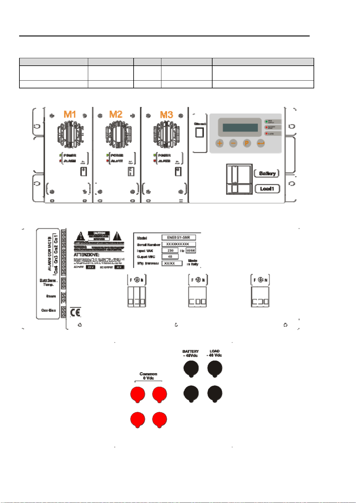
5.2 Front and back view of the system:
Front view (Figure1)
Rear view (Figure2)
Rear DC Output
Load / Battery (figure3)
7
5.3 Synoptic panel
A synoptic panel is located on the front of the energy station. This is used to visualize the various alarms, the state of functioning
and the measurements. It provides immediate signals, either illuminated or acoustic, which illustrate the general condition of the
machine and more detailed information, including various measurements, which the operator can consult by using the keyboard
and the display.
5.4 Acoustic signal
The acoustic alarm activates in case there is an electricity shortage and/or any other operation irregularity should occur. Any key
pressed silent the buzzer.
5.5 Monitor Display
The energy station indicates its state of functioning through various illuminated signals. In reference to figure F1, the signals
illuminated by led diodes are indicated in Chart :
LED MESSAGE MEANING
GREEN LED “PLANT FEED” On with Plant is powered.
Off with Plant isn’t powered.
RED LED “BATTERY MODE” On with line shortage.
Off with line present.
RED LED “ALARM” Usually off.
On for signaling generic alarm.
5.6 Alarm contact
The functioning alarm signals are isolated through relay free contacts available with the indications shown on chart :
RELAY FREE CONTACTS OPEN CLOSE
“CN1” Plant feed 1-3 1-2
“CN2” Battery mode 4-6 4-5
“CN3” Battery Low 7-9 7-8
“CN4” Alarm 10-12 10-11
When running and in normal functioning condition, contacts “CN1” – “CN3” – “CN4” are OPEN
5.7 PROTECTION ELEMENTS
The energy station, SCS2ENMD48, is provided with the following protection:
Output fuses breaker towards the loads are positioned on the front panel of the SCS2ENMD48. If one of this
opens in case of over-current absorption an alarm is generated. This alarm is displayed and set the
corresponding alarm relè.
The AC input fuses are positioned on the front panel of the system together the breaker of the loads and the
battery;
Output low battery voltage to save battery life (43Vdc ± 2%);
Output current limitation.
Output over voltage protection (Vout > 57 Vdc);
Overheating protection;
Thanks to the presence of this protections, it is not necessary to install other types of line protection on the
telecommunication plants which are supplied by the energy station SCS2ENMD48.

8
6.0 FUNCTIONING
Hardware information :
The functioning of the energy station is based on an electronic converter which transforms the line voltage into a isolated
stabilised voltage while all the total running of ENERGY is carried out by an electronic circuit which shows, through a
display and control buttons, the functioning state of the system in real time.
The converter is composed by two sections the first called ‘power factor’ corrector and the second ‘dc/dc push-pull
converter’.
The PFC unit is used to limit the harmonic current equipment is allowed to draw from the main supply. This regulation is
based on the reccomedation of the european normative EN60555-2 . The PFC is composed by a main input voltage
rectifier, an inductor, a power switch (IGBT) and a diode. By controlling the mark space ratio of the switch it is possible
to make the current drawn from the supply closely approximate to a sine wave.When the switch is on the input current is
stored into the inductor. At this point the inductor voltage is reversed to the output capacitor when the power switch is
off. The output voltage of this section, about 400 Vdc, is the feeder of the second section of the energy station.
The dc/dc section, bridge push-pull converter, is composed by a power switches ( IGBT ), an high power transformer and
an output rectifier. An integrated circuit, compare the output voltage with an internal precision voltage reference,
producing a step wave voltage with a variabile duty cycle. The power switches, used as bridge converter, produce a
simmetrical square wave voltage utilized to drive an high power transformer.The high frequency transformer guarantees
the input and output isolation, and using a different primary to secondary turns ratio, it convert the high input voltage
present in the primary side in a low output voltage in the secondary side. The output voltage, square wave, is then
rectified and filtered by an inductor and a capacitor to produce a smooth d.c. voltage.
Whether the line is present or not, an separated fly-back feeder circuit provides the voltage supply for the logic and the
microprocessor. When the energy station is operating on battery mode, a relay disconnects the battery and the load if the
voltage level it’s fall below the 43Vdc level. This is to prevent an excessive discharge of the battery.
Software information :
The microprocessor board, together with analog and digital sensors, controls all the electric parameters as voltages,
currents, fuses and working temperature and their parameters visualized on the main lcd display. When the microcessor,
checking the values acquired, detects a failure visualizes the error message on the main display, stores the information
in the historical register and sets on or offs the corresponding alarm relay.
The free contacts of these relays are useful for telecommunication users, moreover the system parameters and alarm
message are sent trough the Lan interface. An browser program's and a personal computer are necessary to display this
messages. The energy station is also provided with a CAN-BUS interface used to connect together multiple rectifiers in
order to share information and alarms. The single rectifier unit when powered on the first time take automatically an ID
number and save it on memory. Three ID number are present when the SCS2ENMD48 is configured with three rectifier
units. This ID numbers are necessary to visualize the working condition of the selected rectifier on display panel. Three
menù M1,M2,M3, corresponding to the three rectifiers, are present on the display. When I select the M1 menu I can read
the output current, the output voltage, the working temperature and the input AC voltage of the M1 rectifier and at the
same time the green led of the selected rectifier, blinks. In failure case of one rectifier: power-off the broken rectifier
using the front panel switch and remove it. Insert the new rectifier and power-on using the front panel switch. The led
green and red should flash together for a few seconds, the only green led on indicates that it works and the new ID
number has been assigned.
7.0 Display Menù
7.1 Symbol present:
Display Symbol Description
+Move forward
-Move back
PProgram
Enter
V = xx.xV Output voltage (=voltage which feeds the charge).
VR = xxxV Main input voltage.
I = xA Total current supplied by the switching feeder (I = Iload + Ibat).
T = xx Indicates the work temperature of the power modules (M1,M2,M2)
Iload = xx.xA Current absorbed by charge.
Ibat = xx.xA Current absorbed by batteries.
Mx Rectifier module

9
7.2 Display menù
Display Menù
Primary menù N. Secondary menù Explanation
- SYSTEMS OK
V:xx,x I:xx,x
- - The energy station is operative.
- Iload Ibatt
Xx,xA xx,xA
- - Information about current absorbed by
charge and batteries.
- M1 : - -
- M2 : - -
- M3 : - -
Information general to single module
rectifier. Output Voltage, Main input
voltage, total current and temperature.
- AC VOLTAGE - - Voltage main supply.
- BATT.TEMP. - - If a temperature sensor (optional) is
applied to the battery, it indicates the
temperature of the battery and
automatically corrects the output voltage.
2- HISTORICAL 2.1 DISPLAY Shows the list of events and alarms that
occurred.
1…8 >
DD:MM
HH:MM:SS
“EVENT”
Press + and – for visualized the
event by 1 to 8.
Press to exit.
The system memorized until 8 events,
stating the date, time and the event that
happened. The message are saved on a
flash memory, therefore, even if the
system switched off, all error messages
remain securely in the memory.
2.2 CLEAR Erasing of the historical events
DEL.HISTORIC
AL ?
Y or N
Press P for setting, the character
blink, set with + and – for set Yes
or Not, after press P to confirm.
Press to exit.
If select Y the historical menu is deleted.
3- SETUP 3.1 SET DATE Set the system date, is important because
is visualized on the historical menu.
DD:MM:YY
Set by press P, the HH blink,
change with + and – the time,
press P to confirm. Continue with
the mounth and year. Press to
exit.
DD = day
MM = month
YY= year
3.2 SET HOUR Set the hour system.
HH:MM:SS Set by press P, the HH blink,
change with + and – the time,
press P to confirm. Continue with
the minute and second. Press to
exit.
HH = Hour
MM = minutes
SS = seconds
3.3 BATTERY CHARGER Set the current of recharge the battery
CURRENT
BATT
Set by press P, change with + and
– for increase or decrease the
value. Press Pto confirm. Press
to exit.
4- SERVICE 4.1 BATT TEST
Used only with main power voltage
present, for test to efficiency of batteries.
Y or N Press P for setting, the character
blink, set with + and – for set Yes
or Not, after press P to confirm.
Press to exit.
If select Yes, the display begins the test, after few second, the display show :
TEST FAILED A check the battery efficiency is
necessary.
(see the paragraf xxx)
or TEST OK Battery is ok.
4.2 POWER-OFF This command is used for shutdown the
systems and disconnect the battery.
Before use this command set the system
in Battery mode disconnecting the main
power voltage.
Y or N Press P for setting, the character
blink, set with + and – for set Yes
or Not, after press P to confirm.
Press to exit.
If Y is selected the system will be
powered off.

10
8.0 INSTALLATION
8.1 Packing Case
SCS2ENMD48’s packing case contains:
the energy station;
battery and load fuses;
this instruction manual.
ATTENTION: The energy stations are very fragile electronic devices. Be very careful when unpacking and
transporting.
8.2 Preliminary Controls
Before proceeding with the installation of SCS2ENMD48, check if the device has been damaged during delivery. The
energy station should be placed in a well ventilated room, far from any sources of heat and the parts which require
ventilation should not be obstructed.
8.3 Installation / Switching ON
The following installation procedures must be carried out when the energy station is switched on for the first time:
For a correct installation proceed with the following operations:
1) Connect the powering user cable to the corresponding terminals, as the Figure 4:
Figure 4
Linea Monofase 230VAC (1F+N) Linea Trifase 400VAC(3F+N)
NOTE : The connection of the three phase line input is only possible with the 3 power supplies installed and operating.
2) Switch on ENERGY by turning the switch to the “I” position to all modules; the leds of the modules will light up,
and after few second the red led "ALARM" turns off and the LED green "POWER" remains access fixed.
At this point the energy station is turned on. The “MAIN SUPPLY” green led will light up on the synoptic panel
and the display will show:
STARTUP
| | | | | | | ---------------
3) At the end of the ignition the display
SYSTEM OK
V = 54.00 I = xx,xA
4) Switch ON the circuit breakers, situated on the front of synoptic panel .
5) Simulate a black-out by disconnecting the main power;
The “BATTERY MODE” red led will light up on the synoptic panel and the following will appear on the display:
BATTERY MODE
This state of operation is accompanied by an intermittent acoustic signal (10 sec.);
6) Re-insert the main supply. The energy station is now in a normal functioning state and the display will indicate:
SYSTEM OK
V = 54.00 I = xx,xA
7) The energy station is now operative.

11
8.5 SWITCHING OFF
1) Turn the line switch to the “0” position for all modules, the "POWER" green leds turn off.
The “BATTERY MODE” red led will light up on the synoptic panel and the display will read:
BATTERY MODE and the acoustic signal will activate;
2) Enters to menu display by press + and visualize this menu .
4- SERVICE
Press for access to submenu until:
4.2 POWER OFF
Y/N
3) Press P for setting, the character blink, with + and – set Ycharacter and press P to confirm. Exit with press .
The energy station is now off.
NOTE: with this procedure SCS2ENMD48 is totally switch off, after, is possible to move the energy station for
storage or maintenance.
8.6 BATTERY TEST
To test the batteries and test the efficiency, you can make the TEST BATTERY. For making a test enter on the menu 4-
SERVICE and proceed as explained on table 2. After star the test the system carries out a discharge and a recharge the
battery and the display visualized :
BATTERY TEST
V = xx.x V I= 0,00A The test works only with the present load.
If the battery efficiency is up to standard the display indicates:
BATTERY TEST
TEST OK
If, instead, the result of both tests is negative, the display will read:
BATTERY TEST
TEST FAILED
Check the battery voltage, if the value is XX, wait one hour and make the test a second time. If the test fails again,
replace the batteries.
8.7 ERROR MESSAGE
Below is a list of error messages that can be viewed from the synoptic panel:
Error Message Meaning
SYSTEM OK ENERGY is functioning correctly.
BATTERY MODE The battery is discharging. The main voltage is absent. Check the battery voltage on the message
menù.
BATTERY LOW The battery voltage has fallen to 40Vdc. The battery voltage is very low. If there is a line shortage
ENERGY will switch off.
BATTERY FAULT The battery is broken. Change the unit.
OVER-TEMPERATURE The internal energy station temperature is raised to high.
OVER-VOLTAGE ENERGY’s output voltage is out of the maximum variation intervals.
OVER-LOAD ENERGY’s output current is over than the max permissible current, besides the output level voltage
decrease as consequence.
BAR FUSE BROKEN Power fuse broken ( fuse used to protect the power electronic circuit).
INV- FUSE BROKEN Inverter fuse broken.
LOAD- FUSE BROKEN Charge fuse broken.
SUPPLY BROKEN Rectifier is Mx broken. Change the unit.


