www.joy-it.net
Pascalstr. 8 47506 Neukirchen-Vluyn
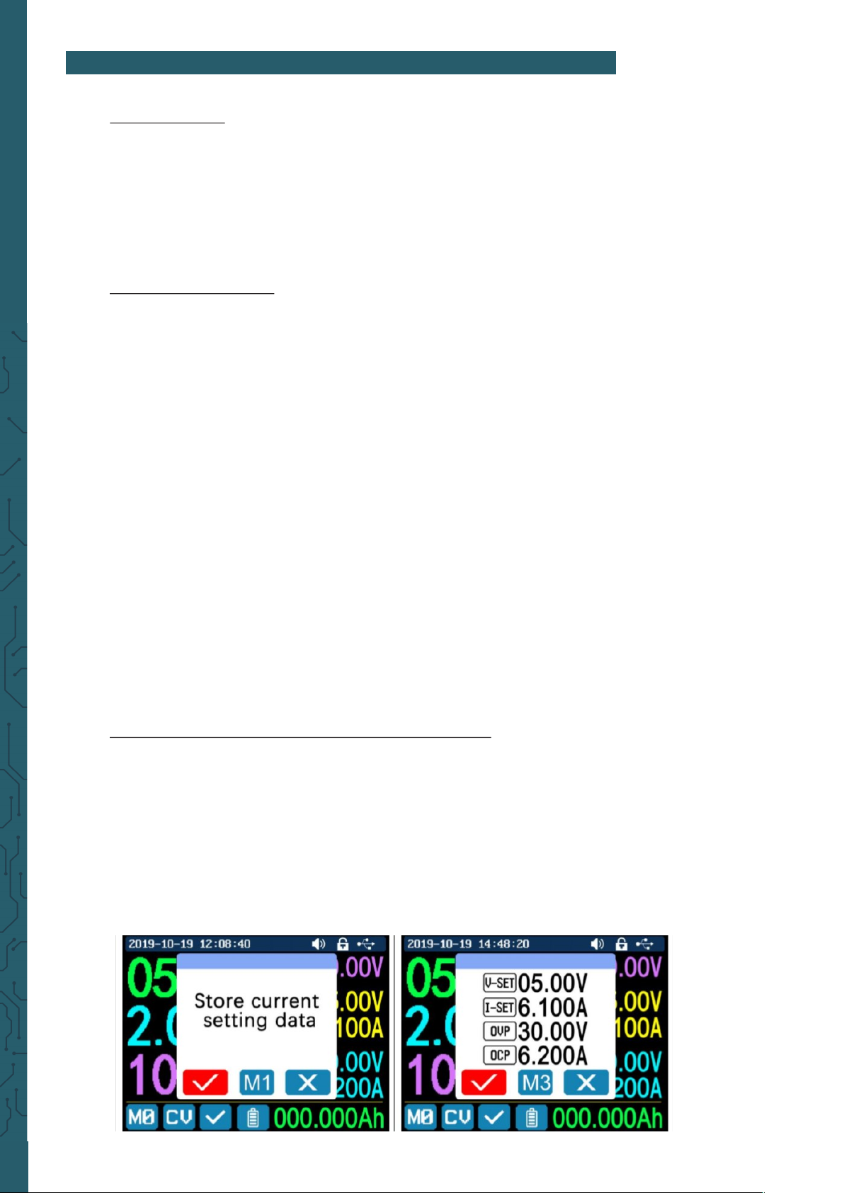
4. Data Group Quick Storage and Callout
Press 'MEM' +keypad button 1-9, you can store the output voltage value, output cur-
rent value, overvoltage protection value, overcurrent protection value into the corre-
sponding data group (as shown above), then press 'ENTER' to confirm, or press the
encoder to cancel. Press 'SHIFT' +keypad button 1-9 to quickly call out the saved data
(as shown above). Press 'ENTER' to confirm, or press the encoder to cancel.
5. Keypad lock and unlock
Press 'SHIFT'+'.' to lock or unlock the keyboard. And the keypad will be automatically
locked when communication starts,
there will be displayed on the top (can not unlock manually) and the keypad will
be automatically unlocked when the connection disconnected manually.
There will be displayed , the keypad will be automatically unlocked when the
connection disconnected abnormally and the power-o button can be used when the
keypad is locked.
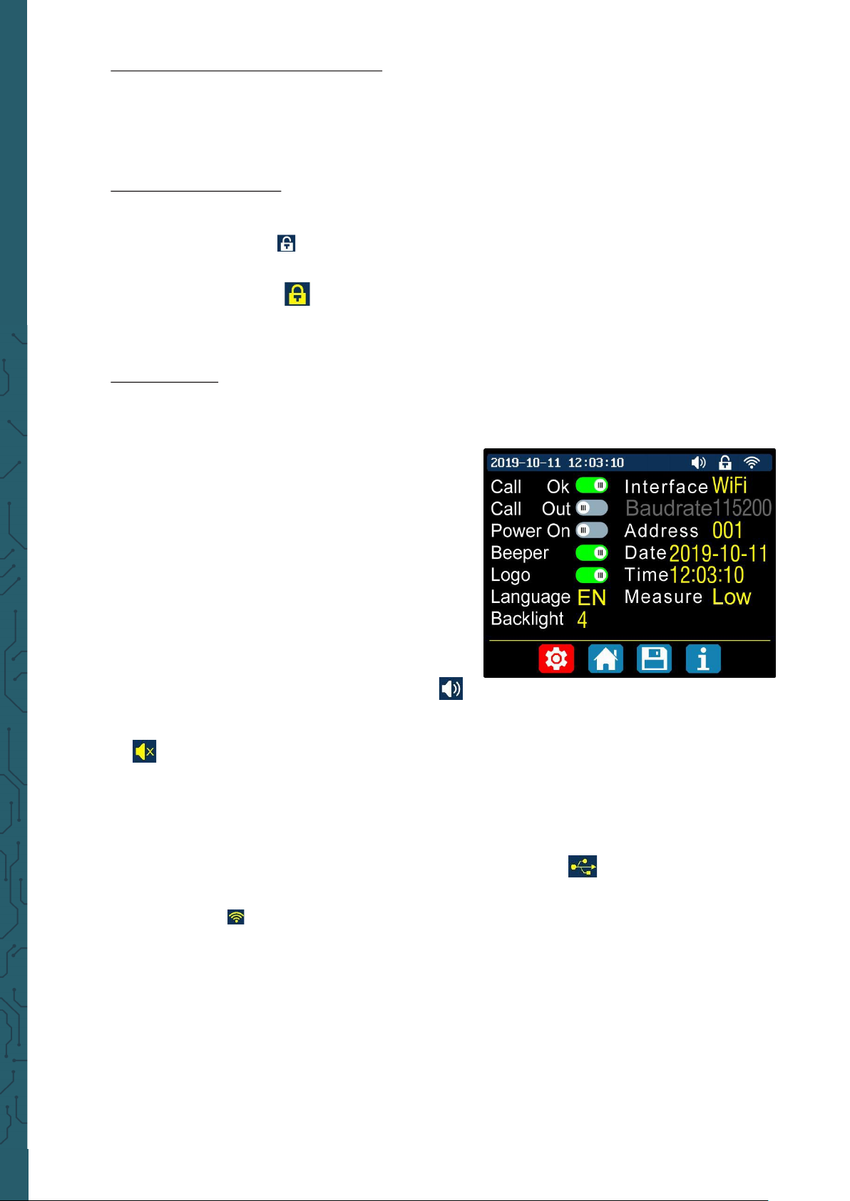
6. System Setting
Press 'SHIFT'+'0' to enter the system setting menu as shown on the right, press
'ENTER' to enter the menu, press direction button to select option, the option in red
is the option be chosen, rotate the encoder to change this setting.
Turn on the 'Call OK', a confirmation window will
pop up when you quick call out a data group. If
you turn it o, the setting values will be modified
directly when you call out a data group.
Turn on the 'Call out', the output will be turned on
automatically when you call out a data group. If
you turn it o, the output will keep the previous sta-
tus.
Turn on the 'Power On', it will turn on the output
automatically when start. If you turn it o, the out-
put will keep OFF status when started.
Turn on the 'Beeper', you will hear button tune
when pressing the button and there will be
on the top.
If you turn it o, there will not be button tune when press the button and there will
be on the top.
Turn on the “Logo”, it will display Logo first and then enter the main page when
booting RD6006 or RD6012. If you turn it o, you will enter the main page directly.
The system language supports English, German, French and Simplified Chinese.
The screen brightness can be set from level 0 to level 5.
The communication interface can be set to USB, Wi-Fi or TTL, USB interface is the Mi-
cro-USB interface on the front panel interface, you can see the
on the top when communication starts.
Wi-Fi interface is the Wi-Fi module connected to the communication interface,
you can see the on the top when communication starts (connect mobile phone
by Wi-Fi, but you need to choose Wi-Fi interface first, Wi-Fi module can not be in-
stalled or removed when RD6006 or RD6012 is powered on), TTL is not available for
the time being.
When the interface is changed, you need to reboot the device to apply the modifica-
tion. The baud rate can be set 9600/19200/38400/57600/115200 under USB mode;
The Baud rate under Wi-Fi is fixed at 115200. The device address can be set from 001-
255. You can set the date and time by rotating the encoder, the setting will be
saved immediately aer modification. Please do not set a wrong time, it may cause
the date to not be automatically accumulated. Press the encoder to return and the
set value will be saved automatically.
Measure is the refresh rate of read back voltage and current on the main page, you
can set it to low, middle and high. Press rotary encoder to return and it will be auto-
matically saved.