SightLine 3000-OEM User guide

© SightLine Applications, Inc.
EAN- Startup Guide 3000-OEM
2020-11-03
Exports: Export Summary Sheet
EULA: End User License Agreement
Web: sightlineapplications.com
1Overview ................................................................1
1.1 Additional Support Documentation.......................1
1.2 SightLine Software Requirements..........................1
2Network Configuration ..........................................1
3Serial Communications ..........................................2
43000-EVAL Kit.........................................................2
5Hardware Bench Setup ..........................................3
5.1 Additional SightLine Adapter Boards .....................4
6Panel Plus...............................................................4
6.1 Camera Setup and Network Selection ...................7
6.2 Direct Serial Connection (optional)........................9
7Summary................................................................9
7.1 Demo Mode .........................................................10
8Troubleshooting...................................................10
8.1 Questions and Additional Support.......................12
CAUTION: Alerts to a potential hazard that may result in personal injury, or an unsafe practice that causes damage to the equipment
if not avoided
IMPORTANT: Identifies crucial information that is important to setup and configuration procedures.
Used to emphasize points or reminds the user of something. Supplementary information that aids in the use or understanding of the
equipment or subject that is not critical to system use.

EAN-3000-OEM Startup Guide
© SightLine Applications, Inc. 1
1Overview
The 3000-OEM Startup Guide provides the steps for connecting, configuring, and testing the 3000-OEM
video processing board on the 3000-IO interface board. The IO board provides the standard
connections for power and communication with the 3000-OEM processing board. Boards with SLE
options enabled use the same startup procedure.
1.1 Additional Support Documentation
Additional Engineering Application Notes (EANs) can be found on the Documentation page of the
SightLine Applications website.
The Panel Plus User Guide provides a complete overview of settings and dialog windows located in the
Help menu of the Panel Plus application.
The Interface Command and Control (IDD) describes the native communications protocol used by the
SightLine Applications product line. The IDD is also available as a PDF download on the Documentation
page under Software Support Documentation.
1.2 SightLine Software Requirements
IMPORTANT: The Panel Plus software version should match the firmware version running on the
board. Firmware and Panel Plus software versions are available on the Software Download page.
2Network Configuration
The 3000-OEM board can be connected directly to the host PC or through a network switch. During
startup, the board sends three DHCP discover requests in three second intervals. It will self-assign the
link-local address of 169.254.1.181 if it does not receive a response.
Refer to EAN-Network Configuration for more network configuration information.
SightLine recommends assigning a static IP on the PC when a DHCP server is not present on the
network.
If you require additional assistance with assigning a static IP address to the host PC, contact your
network administrator or search online for procedures that corresponds with your current PC
operating system.
Figure 1: Network Configuration Options
Host PC
User assigned static
IP: 169.254.1.10
3000-OEM Board +
3000-IO Board
Ethernet Cable
Default IP assigned to the
3000-OEM: 169.254.1.181
Network Switch
or PC Direct

EAN-3000-OEM Startup Guide
© SightLine Applications, Inc. 2
Configuration notes:
•If a wireless adapter is active on the host PC it should be disabled.
•If using the link local address, assign a static IP address to the host PC of 169.254.X.X, where X is
1-254 (do not use 181). Use a subnet mask of 255.255.0.0.
•Problems with outbound streaming are often related to setting/assigning IP addresses and
ports. See the Encoding Configuration settings in EAN-Encoding for advanced settings.
3Serial Communications
For a direct serial connection use the 9-pin serial connection. A serial COM connector is included in the
EVAL kit and must be wired to the board power adapter as shown in Figure 2. The pinout for this cable
can be found in the ICD-3000-OEM document. Connecting to the serial COM port on the 3000-IO board
from a host PC requires a null modem adapter or null modem serial cable.
Use a direct serial connection for troubleshooting or if a network connection cannot be established.
Figure 2: Serial COM and Power Connection
43000-EVAL Kit
Parts listed below are included in the 3000-OEM kit. If your application calls for other options and
interface boards please contact Sales. To review all the interface board options, see the 3000-OEM
Accessories page on the SightLine Applications website.
Table 1: 3000-EVAL Kit
Part Number
Qty
Description
3000-OEM (Rev C)
1
Video processing board
3000-IO (Rev D)
1
Main interface board with standard connections for the 3000-OEM
3000-HDSDI-IN (Rev C)
1
HD-SDI Interface board (connected to 3000-IO board)
SLA-PWR-C12V
1
12V power supply w/5-pin connector for 3000-IO board
SLA-CAB-SMA2BNC
1
Analog out cable
SLA-CAB-MCX2BNC
1
Cable, MCX (RA) to BNC(M) for HDSDI-IN
SLA-CAB-ETH0
1
Ethernet cable CAT 5e 3ft
SLA-CAB-S001
1
9-pin Serial adapter
MSD-ADPT
1
SD Card adapter
MSD-32GB
1
SD Card for recording clips and snapshots
SLA-3000-HSNK
1
3000-OEM test bench heatsink (recommended for benchtop testing)
SLA-CAM-HDSDI
1
HD-SDI 1080p Camera
SLA-PWR-A12V
1
12V power supply for camera
J5 (5-pin)
SLA-PWR-C12V
Null Modem
Serial Cable
to PC
Serial 0
3000-IO
Board
EAN-3000-OEM Startup Guide
© SightLine Applications, Inc. 3
5Hardware Bench Setup
IMPORTANT: To prevent damage to the hardware boards, use a conductive wrist strap attached to
a good earth ground. Before picking up an ESD sensitive electronic component, discharge built up
static by touching a grounded bare metal surface or approved anti-static mat.
The 3000-HDSDI-IN board is connected to VIN1 on the 3000-IO board. The 3000-IO board is used as the
serial and network interface board.
IMPORTANT: To prevent voltage spikes to the board, plug in the power adapter (SLA-PWR-C12V)
to an AC power source first and then connect to the board.
Cable connections:
•SLA-CAB-MCX2BNC: Connects to J1 (MCX jack) on the 3000-HDSDI-IN board and to the green BNC
connector of the 1080p camera.
The yellow BNC connector is for analog use only.
•SLA-CAB-SMA2BNC: Connects to VOUT on the 3000-IO board and to the analog monitor (optional).
•SLA-CAB-ETH0: Connects to the Ethernet port on the 3000-IO board and to the network switch or
host PC.
•SLA-PWR-A12V: Connects to the red camera connector and an AC power source.
•SLA-PWR-C12V: Connects to J5 on SLA-3000-IO board and AC power source.
Power and network connectivity LEDs:
•A green light (LED D2) on the 3000-IO indicates that all boards are powered on. An amber light (LED
D3) on the 3000-OEM verifies network connection.
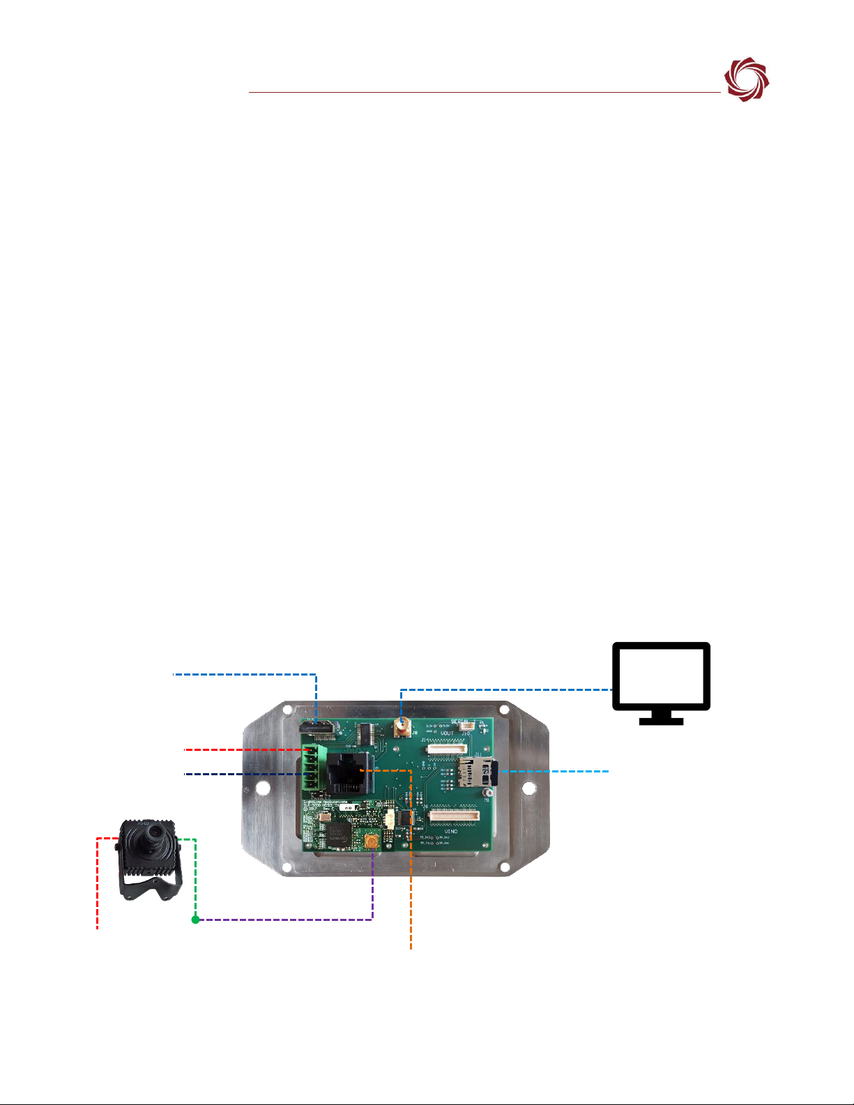
Figure 3: Typical Bench Hardware Setup
Ethernet Port
Network Switch or PC Direct
VOUT
SLA-PWR-C12V
Serial (alternate)
Optional
Analog
Monitor
SLA-CAB-SMA2BNC
SLA-CAB-ETH0
SLA-CAB-MCX2BNC
(VIN1) to camera
3000-OEM +
3000-IO +
3000-HDSDI-IN with heatsink
1080p Camera
SLA-PWR-A12V
HDMI Out
MicroSD Card
HDSDI Input
(Green BNC
Connector)

EAN-3000-OEM Startup Guide
© SightLine Applications, Inc. 4
5.1 Additional SightLine Adapter Boards
SightLine adapter boards provide different I/O, camera inputs, or digital outputs. The boards can be
attached directly to the 3000-OEM or through a secondary adapter allowing customers to swap out
modules for custom configurations. This setup guide assumes the initial use of the EVAL kit and the
HDSDI input. Customer specific configurations with other camera input boards is fully supported.
On the 3000-IO board, VIN0 has camera channels 0 and 1 assigned. VIN1 has camera channel 2
assigned. The 3000-IO board supports installing all SightLine interface boards onto either of these
connectors.
IMPORTANT: 3000-AB board only - If the 3000-AB board is installed on VIN0, both analog inputs can
be used. If it is installed on VIN1, only the J3 (input 0) can be used.
3000-OEM
SLA-3000-IO
Serial Port
Camera Index Panel Plus
J1
0/1
NA
J2
VOUT
4
NA
J3
VIN0
2
CAM0/CAM1
J4
VIN1
3
CAM2
Figure 4: 3000-OEM Serial Port and Connector Reference
6Panel Plus
This section covers the Panel Plus setup and configuration process. Panel Plus provides a basic
graphical interface to the features and functions of the 3000-OEM and 3000-IO board.
Before connecting with the Panel Plus software, the 3000-OEM and 3000-IO boards should be powered
up and connected through:
-a network switch or directly to the host PC (preferred) or,
-Direct serial connection (for troubleshooting or if a network connection cannot be established).
1. Go to the Software Downloads page on the SightLine website and download the Panel Plus
application installer. Older releases are available under the Previous Versions section.
IMPORTANT: The firmware version number and Panel Plus Software version number should match.
If the board firmware version is initially unknown, reference the SightLine invoice that came with
the board when it was purchased.
2. Launch the installer file and follow the prompts. After installation open the Panel Plus application.
3. The first time that Panel Plus is launched, a Windows Security Alert prompt should appear. Select
Allow Access to create a firewall exception (Figure 5).
Approving private network access is sufficient in most cases. Check public networks if directly
connecting to the board.
J1 - Serial Port 0/1 J2 - Serial Port 4
J4/VIN1 - Serial Port 3
J3/VIN0 - Serial Port 2

EAN-3000-OEM Startup Guide
© SightLine Applications, Inc. 5
Figure 5: Windows Security Alert Prompt
IMPORTANT:
•Do not cancel this prompt. Failure to allow access at this point will not allow the Panel Plus
application to connect to the board. See the Troubleshooting section for more information.
•Before using the Panel Plus program, review the Panel Plus User Guide in the Help section of the
Panel Plus application for additional user and setup information.
4. Network connection to the board:
a. From the Connect tab, click the Refresh List button to get a list of boards on the network.
b. Use the dropdown menu and click on the appropriate board to select it.
c. Click the Disconnected (click to connect) button.
Once the connection is successful, the button changes to Connected.
Figure 6: Network Connection to Board
Connected
Click to connect
tconnected
EAN-3000-OEM Startup Guide
© SightLine Applications, Inc. 6
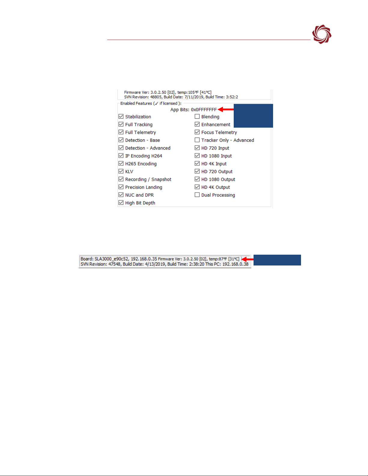
5. Verify the connection:
a. When the Panel Plus has connected to the 4000-OEM board, the firmware version and the
enabled features will be displayed in the Connect tab.
Figure 7: Firmware Version and Enabled Features
b. After connecting the operating information is displayed in the bottom status bar. If the
connection was not successful, this information will not be present or incomplete.
Figure 8: Status Bar Operating Information
IMPORTANT: For optimal performance, monitor the board temperature. Board temperatures
should be below 185°F (85°C). To keep boards within the optimal temperature range, use the
included heatsink during bench testing. For more information about thermal management, see the
ICD-3000-OEM.
Appbit code
with listed
features
Board temperature
EAN-3000-OEM Startup Guide
© SightLine Applications, Inc. 7
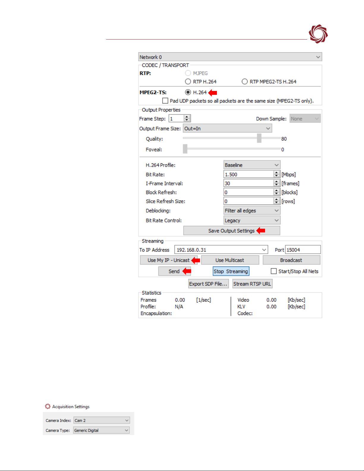
6. Select the Compression tab:
a. Use the H.264 encoding
options to get started.
b. In the Output Properties
section, use the default
values for Frame Step and
Down Sample.
c. In the Streaming
parameters section,
define the destination IP
address and port.
To set these parameters
quickly, click the Use My IP
- Unicast button. This sets
the outbound destination
IP address to the network
interface card on the PC.
d. Click Send to dynamically
set the desired IP Address,
UDP Port, and UDP
delivery format (Unicast,
Multicast, or Broadcast).
e. To save the settings and
make them recurrent
through restarts, main
menu » Parameters »
Save to board.
See EAN-Parameter File
for a comprehensive guide
to saving parameter
settings.
Figure 9: Compression Tab
6.1 Camera Setup and Network Selection
1. From the main menu go to Configure »Aquisition Settings. This dialog window allows changes to
the camera configurations.
2. Since the HD-SDI board is on VIN 1 of the 3000-IO board, set the Camera Index to Cam 2. Set the
Camera Type to Generic Digital.
EAN-3000-OEM Startup Guide
© SightLine Applications, Inc. 8
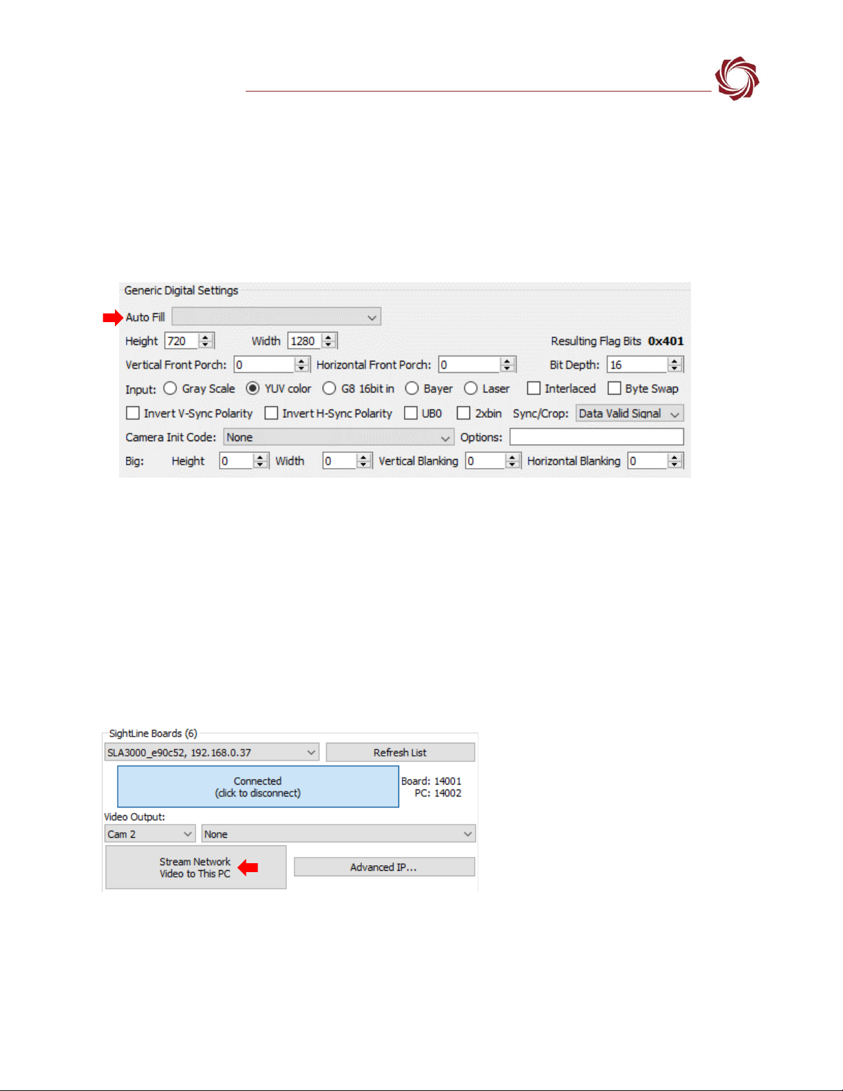
3. In the Auto Fill dropdown menu, select HD-SDI 720p from the Auto Fill menu or enter the Height and Width
settings of the connected camera.
If using a camera that is not configured for 720P, choose the corresponding option under Auto Fill
that matches the camera., e.g., HD-SDI 1030p or HD-SDI 1080p60.
If the camera is listed, the Auto Fill drop-down menu automatically populates the relevant fields
with the correct settings.
4. After changes have been made, the Apply button will turn red indicating that a change has been
detected. Click Apply to apply the changes. Close the Acquisition Settings dialog window.
5. Save and activate the settings:
a. Main menu » Parameters » Save to Board.
b. Main menu » Reset » Board.
c. After the system reboots reconnect to the board. Make sure the board connects.
See EAN-Camera Compatibility for all third-party cameras and lens assemblies that are currently
supported by SightLine software. Includes configuration and setting support guidance.
6. From the Connection tab, click Stream Network Video to This PC.
EAN-3000-OEM Startup Guide
© SightLine Applications, Inc. 9
6.2 Direct Serial Connection (optional)
1. Connect the serial cable to the 3000-OEM board
and host PC as shown in Serial Communications.
2. From the Connect tab, click the Refresh List
button to get a list of available COM ports.
3. Use the dropdown menu and click on a COM
port to select it.
4. Click the Disconnected (click to connect) button.
Figure 10: Direct Serial Connection
7Summary
This completes the startup guide for the 3000-OEM board. See the Panel Plus User Guide (main menu »
Help » User Guide) for additional user and setup information.
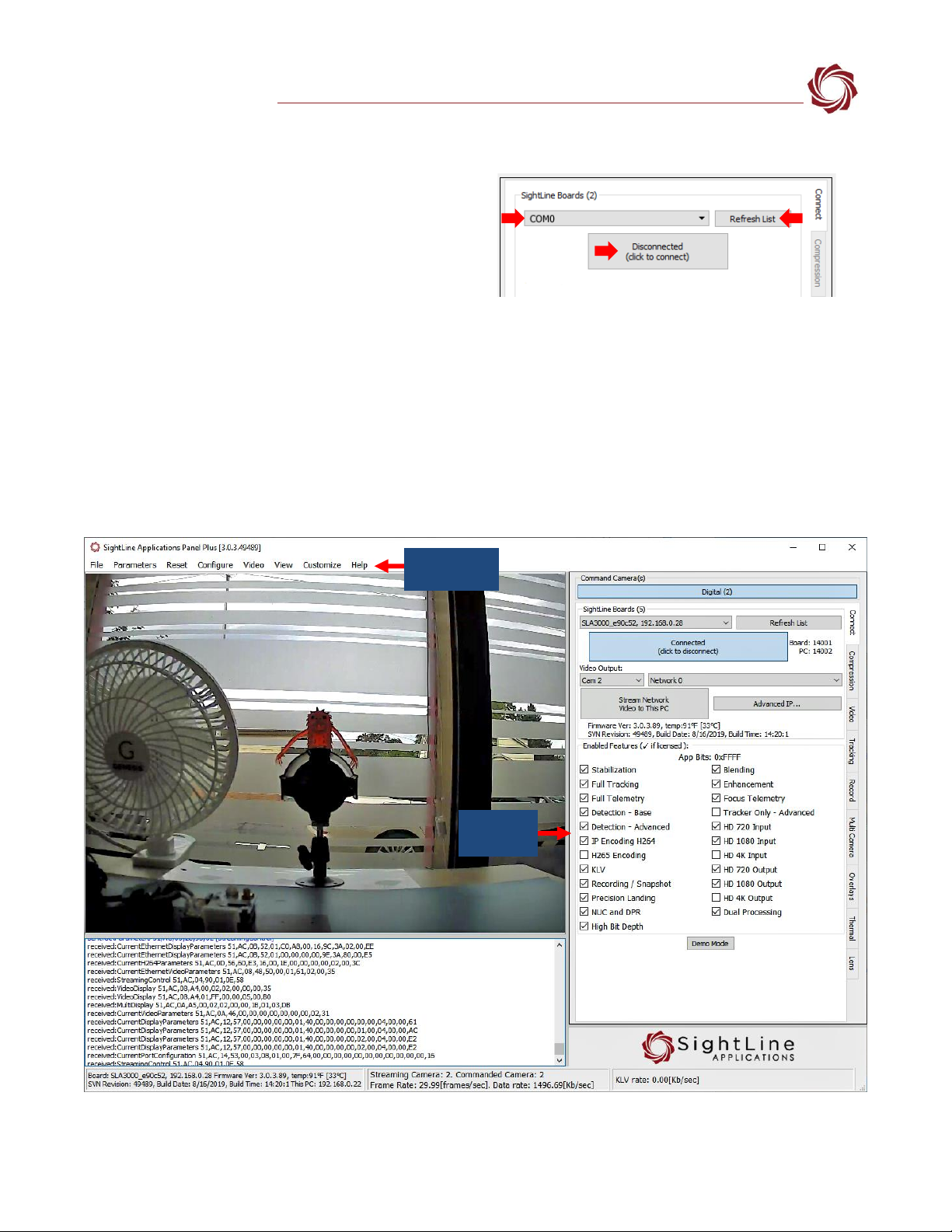
If the board has been connected to a camera and encoding functions are part of the configuration,
video will be displayed in the main window. On the Connect tab of Panel Plus, the purchased functions
are checked and enabled. To add additional features to 3000-OEM board, contact Sales.
Figure 11: Panel Plus Connection to Board
Panel Plus
User Guide
Enabled
Features

EAN-3000-OEM Startup Guide
© SightLine Applications, Inc. 10
IMPORTANT: Not all 3000-OEM purchased configurations include encoded IP video, e.g., the
Tracker-only configuration. For configurations that include encoding, video will be displayed in the
Panel Plus main window. Tracker-only configurations will display processed video on the analog
output only. An analog monitor is required for viewing this output.
7.1 Demo Mode
To enable all features for testing and evaluation purposes, click the Demo Mode button from the
Connect tab. All the features enabled on the board are now available for testing.
The video screen will have a Demo Mode screen overlay until the Demo Mode function is turned off.
8Troubleshooting
Issue: Unable to connect with the Panel Plus application to the 3000-OEM board over a standard
network connection.
Check static IP address:
Check the static IP address configuration. Improper or unknown static IP address setup is a common
connection problem. See the Network Configuration section and EAN-Network Configuration for more
network configuration information.
Check Windows firewall:
Failure to allow access in the Windows Security Alert prompt upon initial startup of the Panel Plus
application can cause connection issues.
1. Close the Panel Plus software application and open the Window Firewall Security Manager on the
host PC.
2. Go to Inbound rules and delete the two slapanelplus rules (TCP and UDP).
3. Re-start the Panel Plus application and allow access in the Windows Security Alert prompt window.
Delete inbound rules

EAN-3000-OEM Startup Guide
© SightLine Applications, Inc. 11
Check hardware connections:
Make sure that all the boards are powered on.
If connecting over the network, switch to a direct serial connection (see the Serial Communications
section. The Panel Plus software will automatically recognize serial ports and list them in the dropdown
menu for available connections.
Connecting to the serial COM port on the 3000-OEM board from a host PC requires a null modem
adapter or null modem serial cable.
Check network configuration:
After communications have been established using the serial connection, networking settings can be
corrected to allow proper network communications.
1. From the main menu, go to Configure » Network Settings.
2. If an unknown static IP address is assigned, remove it or update it to match your network’s
addressing scheme.
Issue: Network output video shows image in upper left corner of Panel Plus with a green background.
Check camera output settings:
The camera could be set to output 720P and the camera setting in Acquisition Settings is set to 1080P.
Changing the camera to 720P in Acquisition Setting should correct this problem.
If the HD-SDI camera came with the 3000-OEM kit, the camera resolution can be changed to 1080P30
using the small controller joystick on the cable included in the kit.
It is easier to read the menus if the yellow output of the camera (analog out) is connected to an
analog monitor.
Check network
settings

EAN-3000-OEM Startup Guide
© SightLine Applications, Inc. 12
1. Press the joystick on the cable to bring up the menu.
2. Scroll down to System.
3. Press the joystick and scroll down to Frame Rate
4. Move the joystick right or left to select 1080P30
8.1 Questions and Additional Support
For questions and additional support, please contact Support. Additional support documentation and
Engineering Application Notes (EANs) can be found on the Documentation page of the SightLine
Applications website.
Other manuals for 3000-OEM
4
Table of contents
Other SightLine Media Converter manuals


Popular Media Converter manuals by other brands


H&B
H&B TX-100 Installation and instruction manual

Bolin Technology
Bolin Technology D Series user manual

IFM Electronic
IFM Electronic Efector 400 RN30 Series Device manual

GRASS VALLEY
GRASS VALLEY KUDOSPRO ULC2000 user manual

Linear Technology
Linear Technology DC1523A Demo Manual

Lika
Lika ROTAPULS I28 Series quick start guide

Weidmuller
Weidmuller IE-MC-VL Series Hardware installation guide

Optical Systems Design
Optical Systems Design OSD2139 Series Operator's manual

Tema Telecomunicazioni
Tema Telecomunicazioni AD615/S product manual

KTI Networks
KTI Networks KGC-352 Series installation guide

Gira
Gira 0588 Series operating instructions

Lika
Lika SFA-5000-FD user guide